manuals.online logo
Brands
  1. Home
  2. •
  3. Brands
  4. •
  5. DUCATI Performance
  6. •
  7. Motorcycle Accessories
  8. •
  9. DUCATI Performance 96680702A User manual

DUCATI Performance 96680702A User manual

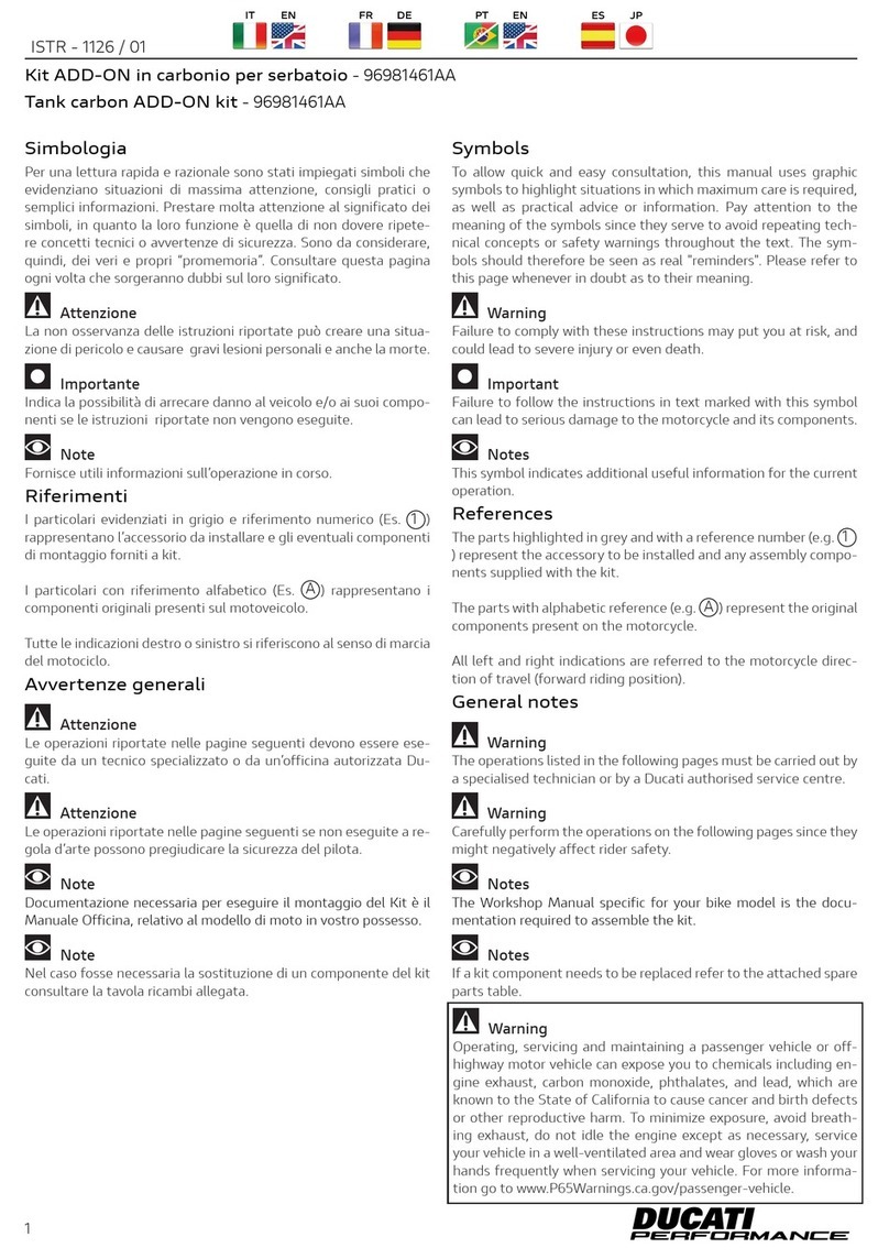
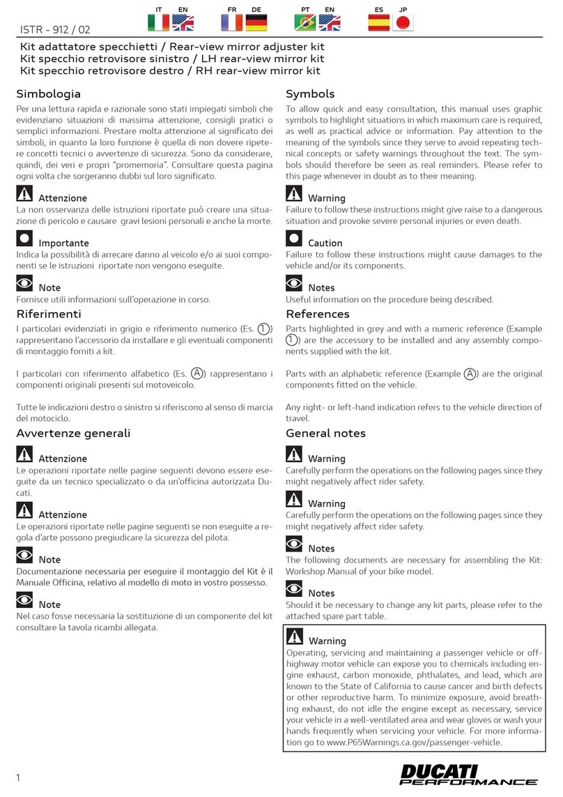
Symbols
The symbols used in this manual are aimed at making reading di-
rect and easy. The symbols are used either to draw the reader's


to these symbols as they are used to remind of technical principles
or safety measures which will not be repeated extensively. They
must therefore be considered as "reminders". Check with this page
in case of doubt about their meaning.

Failure to comply with these instructions may put you at risk and
lead to severe injury or death.

It indicates the possibility of damaging the motorcycle and/or its
components if the instructions are not followed.

It supplies useful information about the operation in progress.
References
 1
) represent the accessory to be installed and any assembly compo-
nents supplied with the kit.
 A) represent the original
components present on the motorcycle.
-
tion of travel (forward riding position).


The operations listed in the following pages must be carried out by
a specialised technician or by a Ducati authorised service centre.




The Workshop Manual of your motorcycle model is the documen-
tation required to assemble the Kit.





highway motor vehicle can expose you to chemicals including en-
gine exhaust, carbon monoxide, phthalates, and lead, which are

or other reproductive harm. To minimize exposure, avoid breath-
ing exhaust, do not idle the engine except as necessary, service
your vehicle in a well-ventilated area and wear gloves or wash your
hands frequently when servicing your vehicle. For more informa-
tion go to www.P65Warnings.ca.gov/passenger-vehicle.
 - 96680702A


       

simboli, in quanto la loro funzione è quella di non dovere ripete-

  
ogni volta che sorgeranno dubbi sul loro significato.

-


-

Note
Fornisce utili informazioni sull’operazione in corso.
Riferimenti
 1)
rappresentano l’accessorio da installare e gli eventuali componenti
di montaggio forniti a kit.
      A) rappresentano i
componenti originali presenti sul motoveicolo.

del motociclo.


-
-
cati.

-

Note
Documentazione necessaria per eseguire il montaggio del Kit è il

Note
Nel caso fosse necessaria la sostituzione di un componente del kit
consultare la tavola ricambi allegata.
 - 96680702A
1
ISTR - 910/ 01


date, please refer to DCS (Dealer Communication System).

           
         
or damaged, screw them until fully home without applying
any excessive force, thoroughly complying with the specified
tightening torque.

    
consultare il DCS (Dealer Communication System) per avere
informazioni sempre aggiornate.

         
non utilizzare avvitatore automatico. Per evitare la deformazione


di serraggio indicata.
Pos. Denominazione Name
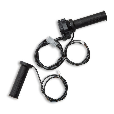
1 Comando acceleratore riscaldato destro 
2 Manopola riscaldata sinistra 
Vite TCEI M4x10 TCEI screw M4x10
4 
2

2
4
1
3
2



        
pin (A2) from the main wiring connector (B1). Disconnect plug (C)


2 screws (A1).



   
      
-

fissaggio paramani destro (D). Allentare le n.2 viti (A1).


A2
B1
A1
D1 D
B2 C
-




fissata alla vite (D1). Sfilare il comando acceleratore (A) dal manu-
brio (E).
4

4
D1
D
D2
A
E




Operando sul lato sinistro del motoveicolo, rimuovere il tappo (C1)
-
stro (G).

5
F
F
C1
G1
G
-




-
nubrio (E).
6

6
G1
G
G2
H
E



To remove the rider seat (L) refer to the instructions on the work-


To remove the tank fairing assembly (M), refer to the instructions
-




Per le procedure di smontaggio della sella pilota (L), fare riferimen-
-


Per le procedure di smontaggio del gruppo carene serbatoio (M),
-


7
ML

Working from the upper side of fuel tank (N), loosen no.2 front fas-
tening screws (N1) with washers (N2). Working on the rear side of






Operando dal lato superiore del serbatoio carburante (N), svitare

lato posteriore del serbatoio carburante (N), svitare la vite poste-



       -
giare i tubi e cablaggi collegati a quest’ultimo.
8

8
N
N3
N4
N1 N2 N2 N1



tank is not shown.
Working on the upper side of the motorcycle, disconnect the throt-

-
ting wiring branches.

Note
Per comprendere meglio lo smontaggio del comando acceleratore
non viene visualizzato il serbatoio carburante.

-

predisposizione manopole riscaldabili.

9
O1 P2 Q1
Q2
P3
Q1
Q2


 


(Q).



-

comando acceleratore (O) dal manubrio (Q).
10

10
QR1
R2
R3
R4
R
O
O2


         
tank is not shown.


     

handlebar (Q).

Note
Per comprendere meglio lo smontaggio della manopola sinistra
non viene visualizzato il serbatoio carburante.
Operando sul lato sinistro del motoveicolo, svitare la vite (S1) con


-
lare la manopola sinistra (T) dal manubrio (Q).

11
Q
S1
S2
S3
S4
S
T



-
ditions. Adopt all necessary precautions to avoid damaging any







          
(E1). Tighten no.2 screws (1B) to the specified torque. Fit the outer

expansion bushing (D2) into hole (E2). Tighten screw (D1) to the
specified torque.



        


operare.

Allentare le n.2 viti (1B) di fissaggio del comando acceleratore (1)
-
stro del manubrio (E).


 -
mento del comando acceleratore (1).
Montare il comando acceleratore (1) inserendo il perno (1A) nel foro
(E1) del manubrio (E). Serrare le n.2 viti (1B) alla coppia indicata.

(E), inserendo la boccola ad espansione (D2) nel foro (E2). Serrare
la vite (D1) alla coppia indicata.
12

12
D1
D
D2
1
E
E1
1A
E2
1B
D1
D
1,5 Nm ± 10%
10 Nm ± 10%
Lay the wirings along the instrument panel as shown in the figure.


rubber ties (T) to tie instrument panel cables by recovering any ex-
ceeding section, as shown in the boxes.



During maximum steering, make sure that there are no hinders

-
        


-
strato nei riquadri.



Verificare che durante la fase di massima sterzata non vi siano im-
pedimenti e che i cavi cablaggio non risultino troppo tensionati.


B1
1C
B2 1D T
T


            



Make sure cable (2A) is not squeezed between handgrip (2) and


-
-
aged, screw them until fully home without applying any excessive
force, thoroughly complying with the specified tightening torque.

-
pansion bushing (G2) into the hole (E4). Tighten screw (G1) to the
specified torque.


sede anteriore della manopola riscaldata sinistra (2), come mostra-
to in figura. Montare la manopola (2) inserendola sul manubrio (E)



e commutatore sinistro (K).


utilizzare avvitatore automatico. Per evitare la deformazione o il
-

di serraggio indicata.
-
na del paramani sinistro (G) sul manubrio (E), inserendo la boccola
ad espansione (G2) nel foro (E4). Serrare la vite (G1) alla coppia
indicata.
14

14
G1
G
G2
E3
K
2
E
E4
2A
3
2,5 Nm ± 5%
10 Nm ± 10%
Lay the wiring along the instrument panel as shown in the figure.

original rubber ties (T) to tie instrument panel cables by recovering
any exceeding section, as shown in the boxes.

During maximum steering, make sure that there are no hinders



Please refer to the owner's manual supplied with the motorcycle
for the activation of heated handgrips.

-
-

nei riquadri.

Verificare che durante la fase di massima sterzata non vi siano im-
pedimenti e che i cavi cablaggio non risultino troppo tensionati.

Note
       
d'uso e manutenzione fornito in dotazione al motoveicolo.

15
F
2BT
T
G1
G
10 Nm ± 10%



-
ditions. Adopt all necessary precautions to avoid damaging any



         
tank is not shown.





          
(Q1). Tighten no.2 screws (1B) to the specified torque. Fit the out-


-




        


operare.

Note
Per comprendere meglio il montaggio del comando acceleratore
non viene visualizzato il serbatoio carburante.
Allentare le n.2 viti (1B) di fissaggio del comando acceleratore (1)
-
stro del manubrio (Q).


 -
mento del comando acceleratore (1).
Montare il comando acceleratore (1) inserendo il perno (1A) nel foro
(Q1) del manubrio (Q). Serrare le n.2 viti (1B) alla coppia indicata.




16

16
QR1
R2
R3
R4
R
1
1B
1A
Q1
Q2
1,5 Nm ± 10%
10 Nm ± 10%
10 Nm ± 10%

-
trol heating pin (1D) to connector (Q1). Use the original rubber ties
(U) to tie the various wirings, recovering any exceeding section, as
shown in the boxes.



During maximum steering, make sure that there are no hinders


comando acceleratore (1C) al ramo cablaggio comando accelerato-


-
strato nei riquadri.



Verificare che durante la fase di massima sterzata non vi siano im-
pedimenti e che i cavi cablaggio non risultino troppo tensionati.

17
U
U1C
1C 1D
1DQ1


         
fuel tank is not shown.

            



Make sure cable (2A) is not squeezed between handgrip (2) and


-
-
aged, screw them until fully home without applying any excessive
force, thoroughly complying with the specified tightening torque.

-
sion bushing (S4) into the hole (Q4). Fit spacer (S2) on screw (S1),



Note
Per comprendere meglio il montaggio della manopola sinistra ri-
scaldabile non viene visualizzato il serbatoio carburante.

sede anteriore della manopola riscaldata sinistra (2), come mostra-
to in figura. Montare la manopola (2) inserendola sul manubrio (Q)



e commutatore sinistro (V).


utilizzare avvitatore automatico. Per evitare la deformazione o il
-

di serraggio indicata.
-
na del paramani sinistro (S) sul manubrio (Q), inserendo la boccola
ad espansione (S4) nel foro (Q4). Inserire il distanziale (S2) sulla
vite (S1), posizionare il paramani sinistro (S) e impuntare la vite (S1).

18

18
Q
V
S1
S2
S3
S4
S
2
2A
3
2,5 Nm ± 5%
Q3
Q4
10 Nm ± 10%
10 Nm ± 10%

heating pin (2B) to connector (Q2). Use the original rubber ties
(U) to tie the various wirings, recovering any exceeding section, as
shown in the boxes.

During maximum steering, make sure that there are no hinders



Please refer to the owner's manual supplied with the motorcycle
for the activation of heated handgrips.

-
tare i vari cablaggi recuperando eventuali esuberi, utilizzando le


Verificare che durante la fase di massima sterzata non vi siano im-
pedimenti e che i cavi cablaggio non risultino troppo tensionati.

Note
       
d’uso e manutenzione fornito in dotazione al motoveicolo.

19
U
U 2B
2B
Q2

Position fuel tank (N) being careful not to damage the pipes and

with washers (N2). Tighten the no.2 screws (N1) to the specified


to the specified torque.


danneggiare i tubi e cablaggi collegati a quest’ultimo e impuntare

viti (N1) alla coppia indicata. Inserire il distanziale (N4) sulla vite
        

coppia indicata.
20

20
N
N3
N4
N1 N2 N2 N1
10 Nm ± 10%
10 Nm ± 10%

Other manuals for 96680702A

1

Other DUCATI Performance Motorcycle Accessories manuals

DUCATI Performance 96981321AA User manual

DUCATI Performance

DUCATI Performance 96981321AA User manual

DUCATI Performance 97381951AA User manual

DUCATI Performance

DUCATI Performance 97381951AA User manual

DUCATI Performance 97180791AA User manual

DUCATI Performance

DUCATI Performance 97180791AA User manual

DUCATI Performance 96513603B User manual

DUCATI Performance

DUCATI Performance 96513603B User manual

DUCATI Performance 96681011AA User manual

DUCATI Performance

DUCATI Performance 96681011AA User manual

DUCATI Performance ISTR-1083/01 User manual

DUCATI Performance

DUCATI Performance ISTR-1083/01 User manual

DUCATI Performance 96780551A User manual

DUCATI Performance

DUCATI Performance 96780551A User manual

DUCATI Performance 97380931B User manual

DUCATI Performance

DUCATI Performance 97380931B User manual

DUCATI Performance 97480211AA User manual

DUCATI Performance

DUCATI Performance 97480211AA User manual

DUCATI Performance 97480161A User manual

DUCATI Performance

DUCATI Performance 97480161A User manual

DUCATI Performance 96780655A User manual

DUCATI Performance

DUCATI Performance 96780655A User manual

DUCATI Performance 96780851A User manual

DUCATI Performance

DUCATI Performance 96780851A User manual

DUCATI Performance 96981341AA User manual

DUCATI Performance

DUCATI Performance 96981341AA User manual

DUCATI Performance 96680572A User manual

DUCATI Performance

DUCATI Performance 96680572A User manual

DUCATI Performance 96780231C User manual

DUCATI Performance

DUCATI Performance 96780231C User manual

DUCATI Performance 96781310B User manual

DUCATI Performance

DUCATI Performance 96781310B User manual

DUCATI Performance 96780761B User manual

DUCATI Performance

DUCATI Performance 96780761B User manual

DUCATI Performance 96981461AA User manual

DUCATI Performance

DUCATI Performance 96981461AA User manual

DUCATI Performance Multistrada 1200 User manual

DUCATI Performance

DUCATI Performance Multistrada 1200 User manual

DUCATI Performance 96781421A User manual

DUCATI Performance

DUCATI Performance 96781421A User manual

DUCATI Performance 96981261AA User manual

DUCATI Performance

DUCATI Performance 96981261AA User manual

DUCATI Performance 96781491AA User manual

DUCATI Performance

DUCATI Performance 96781491AA User manual

DUCATI Performance 96780231C User manual

DUCATI Performance

DUCATI Performance 96780231C User manual

DUCATI Performance 97480171A User manual

DUCATI Performance

DUCATI Performance 97480171A User manual

Popular Motorcycle Accessories manuals by other brands

SRC H-ADV150-04-01AL quick start guide

SRC

SRC H-ADV150-04-01AL quick start guide

DMD P1 owner's manual

DMD

DMD P1 owner's manual

GIVI Airflow AF1110 manual

GIVI

GIVI Airflow AF1110 manual

Suzuki 99143-00A1 000 Series installation instructions

Suzuki

Suzuki 99143-00A1 000 Series installation instructions

Cardo Systems FREECOM 4+ Pocket guide

Cardo Systems

Cardo Systems FREECOM 4+ Pocket guide

Shark S 700 user manual

Shark

Shark S 700 user manual

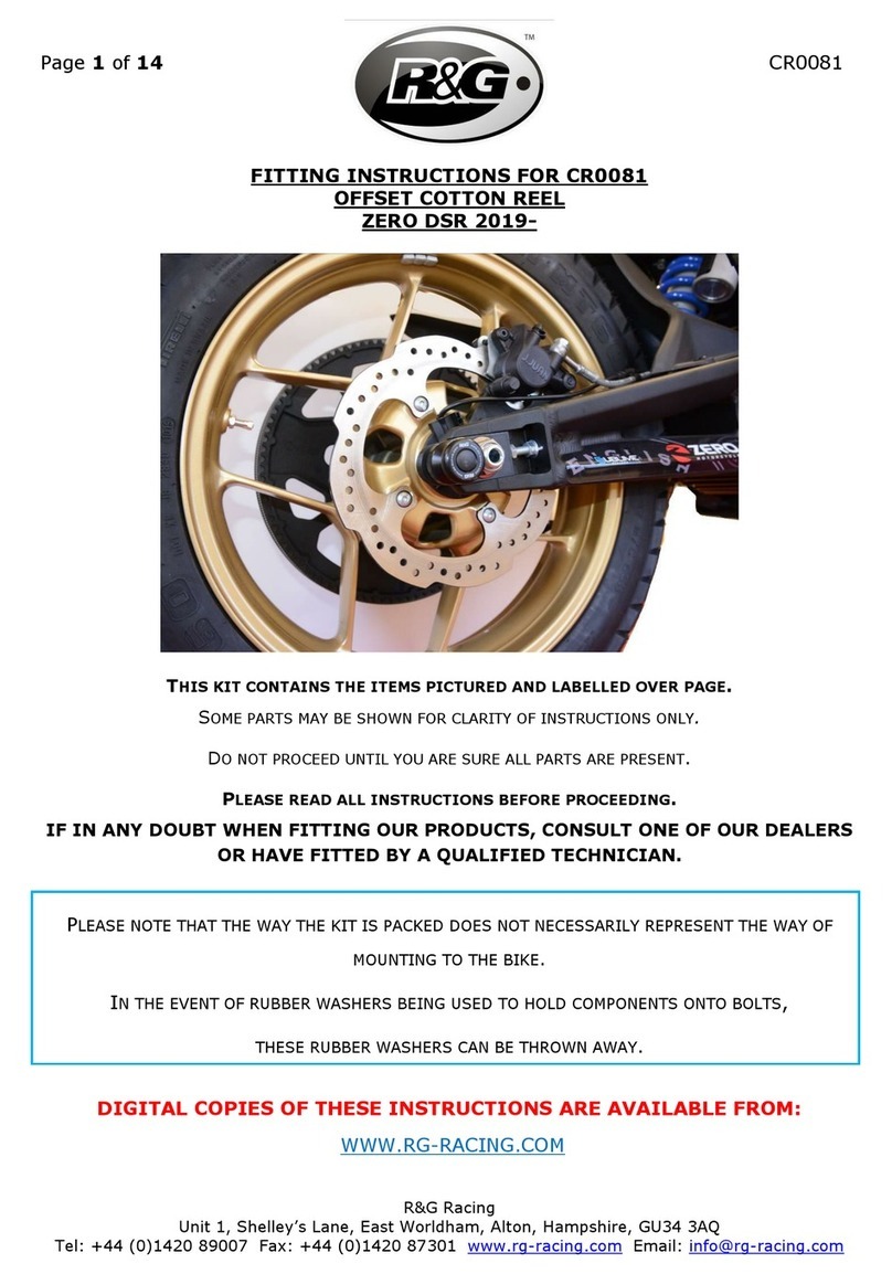
R&G CR0081 Fitting instructions

R&G

R&G CR0081 Fitting instructions

SRC B-TRK502-01-01-SL quick start guide

SRC

SRC B-TRK502-01-01-SL quick start guide

hepco & becker 6307520 00 01 manual

hepco & becker

hepco & becker 6307520 00 01 manual
HOMCOM AA0-077 user manual

HOMCOM

HOMCOM AA0-077 user manual

hepco & becker 6307558 00 01 manual
hepco & becker

hepco & becker 6307558 00 01 manual

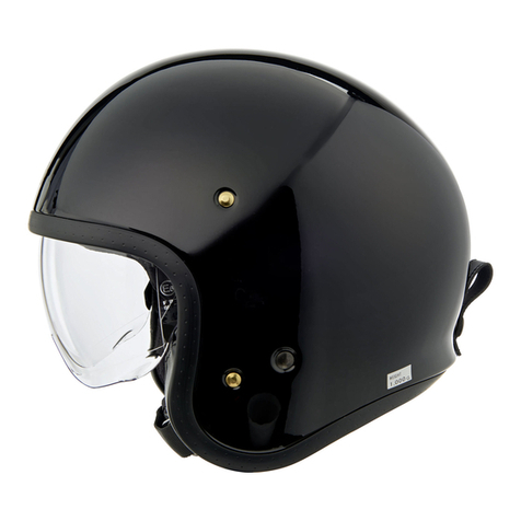
SHOEI JO Instructions for use

SHOEI

SHOEI JO Instructions for use

Wunderkind Custom 106503-F15 Installation and safety

Wunderkind Custom

Wunderkind Custom 106503-F15 Installation and safety

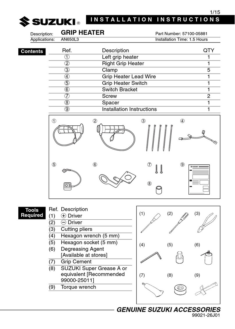
Suzuki 57100-05881 installation instructions

Suzuki

Suzuki 57100-05881 installation instructions

SIKH HELMETS Y-61 quick start guide

SIKH HELMETS

SIKH HELMETS Y-61 quick start guide

Dräger HPS 3500 Instructions for use

Dräger

Dräger HPS 3500 Instructions for use

M-WAVE SKI manual

M-WAVE

M-WAVE SKI manual

Kuryakyn 6212 installation instructions

Kuryakyn

Kuryakyn 6212 installation instructions

manuals.online logo
manuals.online logoBrands
  • About & Mission
  • Contact us
  • Privacy Policy
  • Terms and Conditions

Copyright 2025 Manuals.Online. All Rights Reserved.