Shindaiwa DGM60MK User manual

OWNER
’
S AND OPERATOR
’
S MANUAL
Vertical, Water-Cooled 4-Cycle Diesel Engine
DGM60MK/LU
X750-020 73 0
X750801-370 0
CAUTION
Do not operate the Generator, or any other appliance, before you have read and
understood the instructions for use and keep near for ready use.


Introduction
Thank you for purchasing this Shindaiwa soundproof dieselengine generator.
Thismanualhas been created to ensuresafe usage of this generator. Be sure to readthis
manualbeforeoperation. Improper operation/handling of this generator will result in an accident
ormalfunction.
Handling/Operation of this generator can only be performed by persons who understandthe
contents of this manualand can handle/operate the generator in a safemanner. Persons who
suffer from an illness, are taking medicineor not feeling waysuch that safe operation would be
negatively affected must not operate this generator.
Work performedusing this generator and handling/operation of this generator must bein
accordance with corresponding laws and regulations based on such laws. Consult with the
authorized distributor where this generator was purchased if you have any inquiries regarding the
corresponding laws.
Always besureto includethis manual when loaning outthis generator and instruct operating
personnelto readthismanualbefore operation.
Storethis manualin a specified location where it will be secure and available for consulting at any
time.Order another copyfrom the authorized distributorwherethis generator waspurchasedif
thismanual becomes dusty,grimyor torn.
Consult with theauthorizeddistributor wherethis generator waspurchased if you have any
inquiries regarding anypointsrelatedtothisgenerator andmanual.
When inquiring about this generator, be sure to provide the model name and serial number.
If disposing of this generator, do so in a manner that is in compliance with laws relatedto
industrial waste. Contact the authorized distributor where thegenerator was purchasedif you
have any inquiries regardingproper disposal.
Cautionnotice ranks inthismanual areclassified as follows.
WARNING : Indicates a potentially hazardous situation which, if not
avoided, can result in death or serious injury
CAUTION : Indicates a potentially hazardous situation which, if not avoided,
can result in minoror moderate injury and propertydamage.
< NOTE > : Othertypes of cautions and indications.
Note that CAUTION items can also lead to major accidents under somecircumstances if
not correctly followed.
All caution notices areimportant. Besure to followall of them.

1
Table of Contents
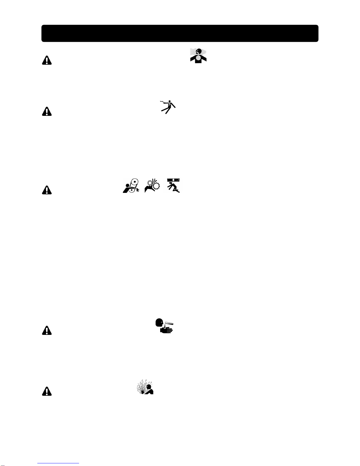
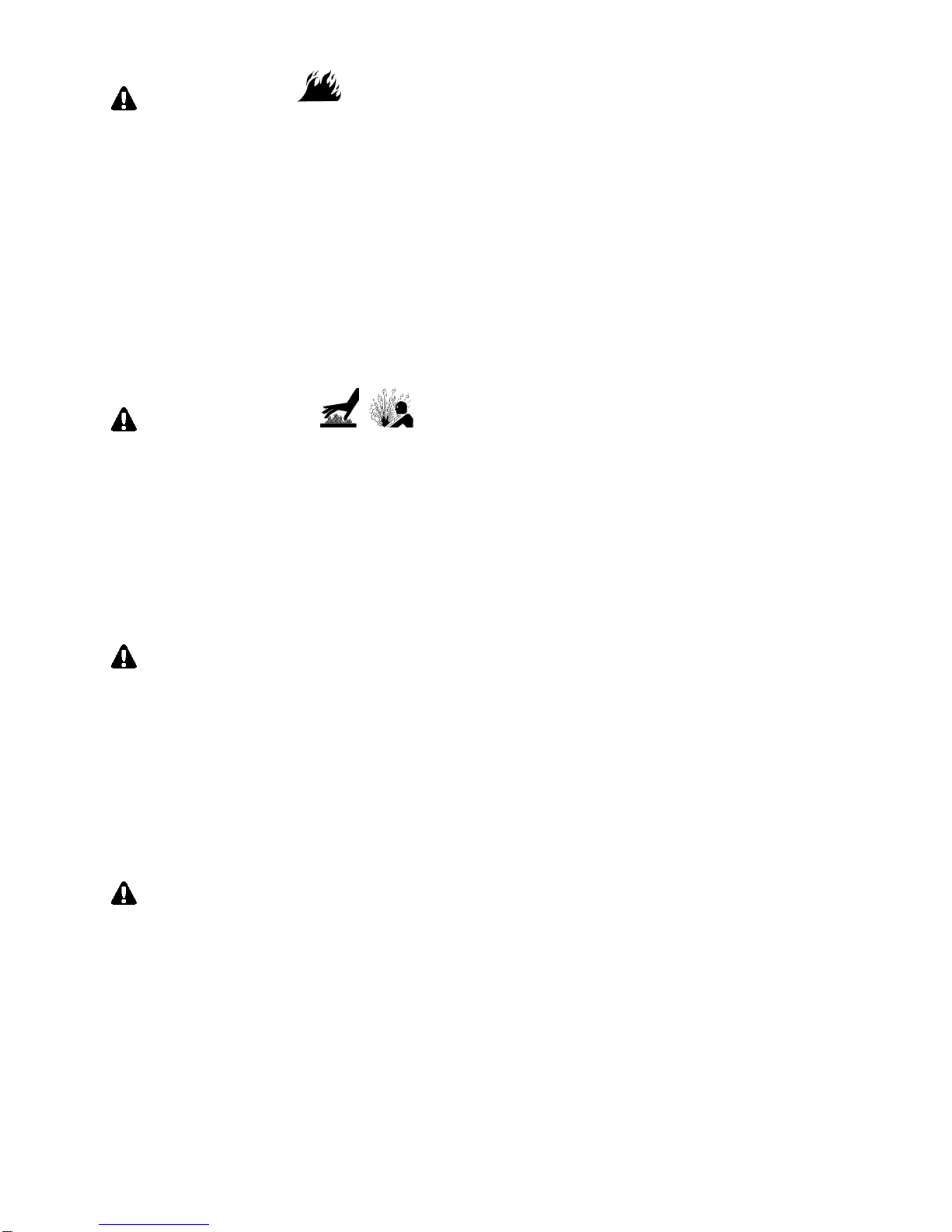
1. Safety Instructions .......................................................................... 2
2. Specifications .................................................................................. 5
2-1. Specifications............................................................................5
2-2. Ambient Conditions...................................................................6
3. Applications.....................................................................................6
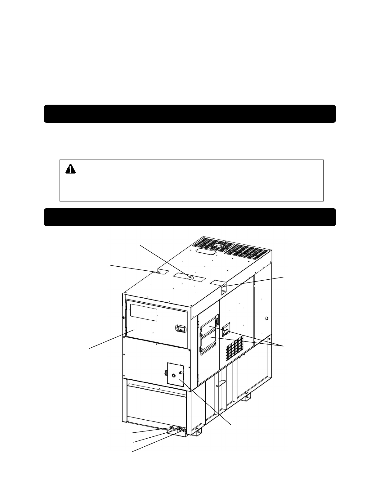
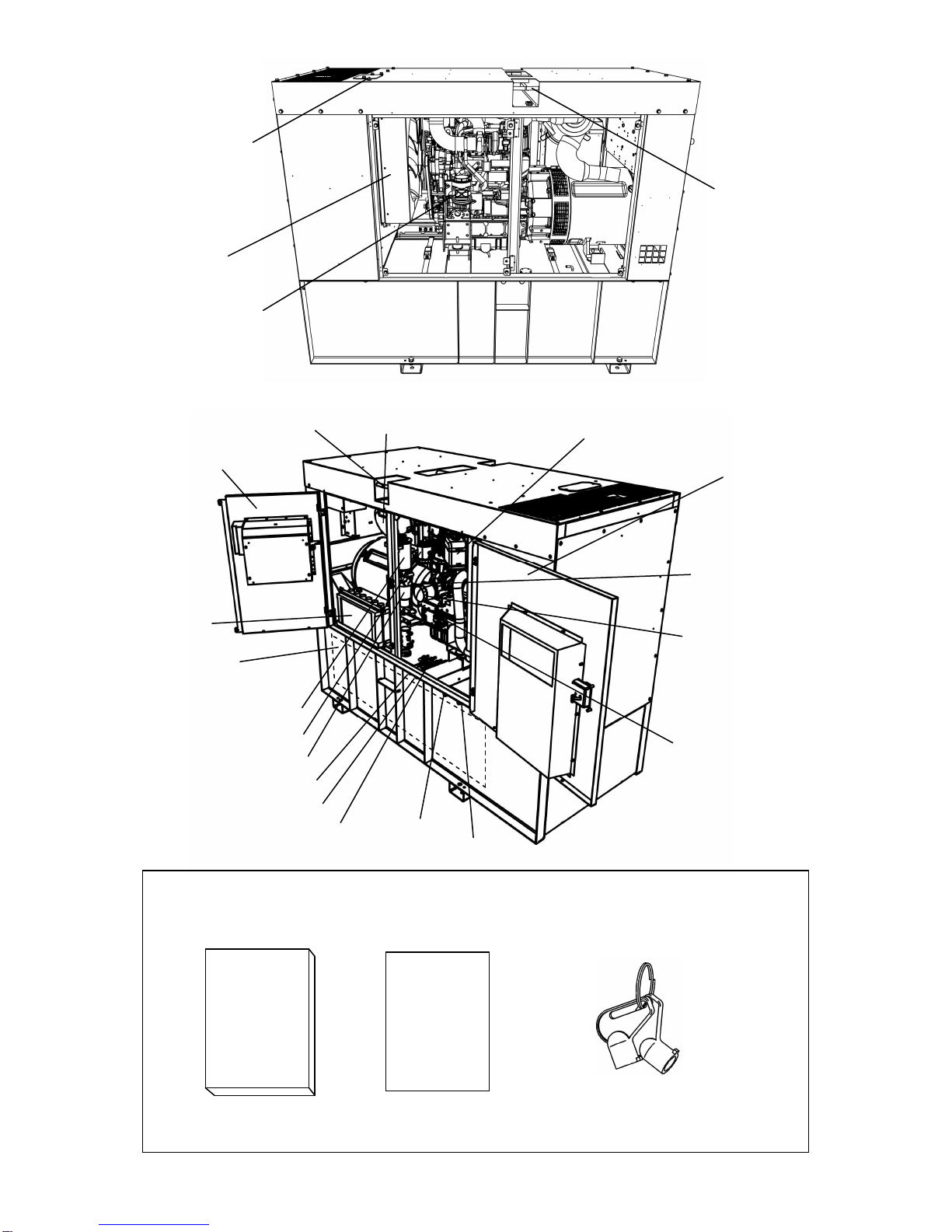
4. Part Names.......................................................................................6
4-1. External View/Part Names ........................................................ 6
4-2. Operation Panel Part Names ....................................................8
5. Equipment........................................................................................9
5-1. Available Output Monitor...........................................................9
5-2. Warning Indicators ....................................................................9
5-3. Meters and Gauges................................................................. 11
5-4. Spill Containment ....................................................................14
5-5. Fuel Piping Switch (3Way Fuel Valve).....................................14
6. Transporting/Installing..................................................................15
6-1. Transport Procedures..............................................................15
6-2. Installation Procedures............................................................16
7. Load Connections ......................................................................... 17
7-1. Load Cable Selection..............................................................17
7-2. Connecting Load Cables......................................................... 18
8. Pre-Operation Inspection.............................................................. 21
8-1. Checking Engine Oil................................................................21
8-2. Checking Coolant....................................................................22
8-3. Checking the Fan Belt.............................................................23
8-4. Checking the Fuel ...................................................................23
8-5. Checking the Spill Containment ..............................................24
8-6. Checking for Fuel, Oil and Coolant Leaks...............................24
8-7. Checking the Battery...............................................................25
9. Operating Procedures................................................................... 26
9-1. Initial Startup/Pre-Check..........................................................26
9-2. 240/480-V Switching Function................................................. 27
9-3. Procedures during Operation..................................................28
9-4. Stopping Operation .................................................................28
9-5. Protective Functions................................................................29
9-6. Connecting with External Fuel Tank........................................30
10. Inspection/Maintenance................................................................ 31
11. Long-Term Storage........................................................................39
12. Troubleshooting............................................................................. 40
13. Generator Circuit Diagram............................................................ 43
14. Engine Electrical Circuit Diagram................................................ 44

2
1. Safety Instructions
WARNING : EXHAUST GAS POISONING
Do not operate the generator in poorly ventilated areas suchas indoorsor tunnels, as theexhaust
gas of the engine contains substances that are harmful tohumanhealth.
Do not direct exhaust fumes at bystanders or buildings.
WARNING : ELECTRIC SHOCK
Before connecting or disconnecting loadcables to/from theoutput terminal, always turn the output
circuit breakers to the OFFposition, stop the engine, and remove the ignitionkey.
Close the output terminalcover before operating.
Do not insert a pin, wireor other metalobject into theelectrical outlet.
Do not touchthe generator if the generator or casing becomes wet during operation.
Do not touchoutput terminalsor internal electric partswhilethegenerator isoperating.
WARNING : INJURY
Closeall doors and lock themduring operation.
Do not openthe check door during operation. Be careful of pinching or catching of moving parts
such asthecooling fan and fan belt.
Always besureto stop the engine and remove the engine keywhen performing inspection or
maintenance.
Do not suspend using tie downs. Use of such could result in the generator falling.
Do not lift any additional weight such as fueltanks or trailers.
No personsshouldbe underasuspendedgenerator.
Always besuretocheck that the breakers onloadside andswitchesfor any equipment using the
generatorareatOFFbefore turning the breakertoON.Also besureto advise personnelon the
loadside that power will be turnedon or off before operating the breaker.
Do not use thefuel tank lifting hook to suspend a gas tank that contains fuel, anddo not suspend
with the fueltank and spill containment as a single unit. Doing so couldresult in the tank falling.
CAUTION : EYE/SKIN INJURY
Wear rubber gloves and other protective wear to protect eyes, skin and clothing from the battery
fluid which contains dilutedsulfuric acid. If thebattery fluidcontacts eyesor skin, wash out
immediatelywith a sufficient amount of clean water. Be sure to receive medicaltreatment,
especiallyif the fluid contacts the eyes.
CAUTION : EXPLOSION
Never use or recharge thebattery if the fluid level is below the minimum level.
Do not create sparks or bring flame near thebattery as it generatesflammable gas.

3
CAUTION : FIRE
Do not bring flammable items (such as fuel, gas and paint) or items that are highly combustible
near thegenerator as the muffler, exhaust gas and other parts become extremely hot.
Position this generator 3 ft. (1 m) or more from walls or other hindrances, and on a levelsurface.
Do not connect thegenerator output to indoor wiring.
Thisgenerator uses diesel fuel.Always be sureto stoptheengine and not bringflames close
when inspecting fuel or refueling.Wait until theengine has cooledbefore performing such
procedures.
If fuelspills, always be sureto openthe spill containment drainvalve and drainoff the spilledfuel.
If fuelor oil is leaking, repair the leaking location before operating.
Always besureto wipe up anyspilled fuel or oil.
Allowthegenerator to cool beforecovering withthe protective cover.
Neverallowflame tocomeclose to thegenerator.
CAUTION : BURNS
Do not touch the engine and surroundingcomponents immediatelyafter stopping theengine as
theyarestillhot.
Do not openthe radiatorcap immediately after stopping the engine. Doing so will result in hot
steam gushing out.
Hot steam gushes out from the coolant sub-tank if the generator overheats. Do nottouch the
coolant sub-tank.
Always besureto stop the engine and allowthe engine to coolwhen performing inspection or
maintenance of engine oil. Opening the oilgauge or oil filler cap during operation will result in hot
oil gushingout.
CAUTION : INJURY
Always besuretouse lifting hookswhensuspending the generator, and slowly lift it straightup.
Personnel performing suspensionwork must wear protective gear such as helmets, safety shoes
and gloves.
Remove the woodties if using anchors to secure the generator
Position thegenerator on a levelstable surfaceso that it cannot slide or move in anymanner.
Before starting operation, always be sure to turnoff all switches of equipment using the generator
and all breakerstoOFF.
Do not move the generator during operation.
Do not operate the generator if it has been modified or anyparts have beenremoved.
CAUTION : PROPERTY DAMAGE
If using this generator for medical equipment, check beforeuse withthe medical equipment
manufacturer, doctor, hospitalor similar entity.
Check that the generator output setting, output terminalconnection and loadpower sourceare
consistent.
Cable burnout can occur due to generated heat if the load current exceeds theallowable current
of the cable.
The voltagedrop between cables is largeif the cable is excessively long or thin, resulting in
decreased input voltageto equipment using the generator,thereby causing decreased
performance, faulty operation andmalfunction.

4
Warning/Caution Label Locations
If warning or caution labels become damaged and difficult to read, replace with new labels in
the indicated locations. Order labels using part number indicated in the parenthesis.
Injury (Part no. : X505-004630)
Simul-Phase (Part no. : X505-006960)
Caution: gm spec LLC (Part no. : X505-004650)
Caution: fire (Part no. : X505-004880)
Caution: do not change (Part no. : X505-004620)
Injury (Part no. : X505-006970)
Danger caution (Part no. : X505-004660)
Burn (Part no. : X505-004400)
Spill containment bolt (Part no. : M707-000380)
Terminal cover instructions (Part no. : M704-002250)
○
11
Continuous output (Part no. : M705-000650)

5
2. Specifications
2-1. Specifications
Model Unit DGM60MK/LU
Generator Type - Revolving Field Brushless AC
Simultaneous 3 Phase-120V/240V
1 Phase
Rated Frequency Hz 60
kVA
60
Three phase kW
48
kVA
36/ [18] *1
Rated Output Single phase kW
36/ [18] *1
Three phase V 208/240/ [480] *1
Rated Voltage Single phase V 120/139/240/[277] *1
Three phase-208V
A 144
Three phase-240V
A 144
Three phase-480V
A 72
Single phase-120V
A 150×2 [75 x 2]*1
Rated Current
Single phase-240V
A 150 [75]*1
Power Factor - Three phase 0.8, Single phase 1.0
Insulation class - F
Excitation - Self Excitation (brushless)
Alternator
No. of Poles - 4
Type - Vertical Water-Cooled 4-Cycle Diesel
Model(Manufacturer) - Kubota V3800DI-TI
No. of Cylinders
(bore × stroke) (in./mm) 4 (3.94×4.72/100×120)
Continuous Rated
Output hp 77
Rated Speed rpm 1800
Displacement Cu.in./liters 230/3.769
Combustion System - Direct Injection (Turbo-charged)
Cooling Method - Radiator
Lubricating Method - Forced Lubrication
Starting Method - Electric
Fuel - No. 2-D EPA regulation
Lubricating Oil - CF class or higher
Fuel Tank Capacity gal./liters 111/420
Lubricant Volume gal./liters 3.5/13.2 (including filter 0.1/0.4)
Cooling Water Volume
gal./liters 3.3/12.5 (including sub-tank 0.4/1.6)
Starting Motor Capacity
V-kW 12-3.0
Charging Alternator
Capacity V-W 12-960
Engine
Battery Capacity - 12V-92AH
Length in./mm 78/1970
Width in./mm 35/880
Height in./mm 64/1630
Dry Weight lbs./kg 2843/1290
Unit
Installed Weight lbs./kg 3703/1680
*1: Output is that shown in brackets if using with the 240/480-V switching function set to 480 V.

6
Lifting Hook
Tie-Down
Tie-Down
Operation Panel Door Terminal Cover
Fuel inlet
Fuel Drain plug
Spill Containment Drain valve
Spill Containment Drain plug
2-2. Ambient Conditions
Use this generator in ambient conditions as described below. Failure to provide these
conditions can result in problems such as malfunction, insufficient output and reduced
durability.
■ Ambient temperature: 5 to 104 °F (-15 to 40 °C)
■ Relative humidity: 80% or less
■ Elevation: 984 ft. (300 m) or less
3. Applications
Power source for submerged pumps and similar civil engineering equipment
Power source for lighting and similar equipment
Power source for electrical tools and household appliances
4. Part Names
4-1. External View/Part Names
CAUTION : PROPERTY/SECONDARY DAMAGE
Do not use for any application other than those listed above.
If using this generator for medical equipment, check before use with the
medical equipment manufacturer, doctor, hospital or similar entity.

7
Oil Filler
Oil Filter
Oil Level Indicator
Water Separator
Fuel Filter
Battery
Fuel Tank
Tie-Down
Alternator Check Door
Air Cleaner Coolant Sub-Tank
Engine Check Door
Fuel Pre-Filter
External Tank Fuel Inlet
External Tank Fuel Return
Oil Drain plug
Coolant Drain plug
3way fuel valve
Radiator Plate
Radiator
Tie-Down
Oil Separator
* Shown with side-plate removed.
Accessories
Owners
Manual
Engine
Warranty
Starter Key (2 pieces)

8
4-2. Operation Panel Part Names
3-Phase Circuit Breaker
○
11
Engine Monitor
1-Phase Circuit Breaker
○
12
Oil pressure/Water Temperature/Speed
Selector Switch
Voltmeter
○
13
Display Selector Switch
Ammeter
○
14
Available Output Monitor
Frequency Meter
○
15
Fuel Meter
Pilot Lamp
○
16
Hour Meter
Voltage Regulator
○
17
Pre-Heating Indicator
Ammeter Selector Switch
○
18
Starter Switch
Breaker Trip Selector Switch
○
19
Throttle Switch
Warning Indicators
○
20
Voltage Selector Switch

9
5. Equipment
5-1. Available Output Monitor
The available generated output for each output power source is displayed digitally. You can
use the display selector switch to change the display in the following order: three-phase,
single-phase three-wire U-W output, and single-phase three-wire U-N/G output. Three-phase
output is constantly displayed when the engine is stopped.
< NOTE >
Consider thedigitally displayed available output as an
approximateestimate. Be especiallysure to thoroughly
considerthe displayed valueandthe usedloadcapacitywhen
using a load suchas that of a motor witha large starting
capacity.
The displayed output capacity might not becorrect valuesif
usingafour-wireconnection (single-phase using theN/G
terminal) for a three-phase output power source. Connect to a
single-phase/three-linetype power source if using a
single-phasepowersource.
If “- -” is displayed for the available output, it means that usage
has exceededthe rated capacity. Immediatelystop the equipment being used and reduce the
loadcapacity of the equipment.
5-2. Warning Indicators
This generator is equipped with the following warning indicators: BATTERY (battery charge),
OIL PRESS (engine oil pressure), WATER TEMP (coolant temperature), OVER SPEED
(engine overspeed), AIR FILTER (air cleaner clogging), SPILL CONTAINMENT (spill
containment amount), and ENGINE (engine malfunction). An indicator lights up if a
malfunction/fault occurs during operation and the engine automatically stops depending on the
fault type. Moving the starter switch from STOP to RUN causes the following indicators to light
up for approximately 0.5 sec.: OIL PRESS, WATER TEMP, and ENGINE.
WARNING : INJURY
Do not open the check door during operation. Be careful of pinching or
catching of moving parts such as the cooling fan and fan belt.
Always be sure to stop the engine and remove the engine key when
performing inspection or maintenance.
CAUTION : BURNS
Do not touch the engine and surrounding components immediately after
stopping the engine as they are still hot.
Display Selector
Switch

10
(1) WATER TEMP (Coolant Temperature) Warning Indicator (High Water Temp.)
CAUTION: BURNS
Do not open the radiator cap immediately after stopping the engine.
Do so will result in hot steam gushing out.
Hot steam gushes out from the coolant sub-tank if the generator overheats.
Do not touch the coolant sub-tank.
If the coolant temperature rises above 230 °F durin g operation, the WATER TEMP and
ENGINE warning indicators light up, and the engine automatically stops. If this occurs, hot
steam will gush out of the coolant sub-tank. Check the coolant sub-tank coolant level after
the generator cools and add coolant to the coolant sub-tank if it is insufficient. (Refer to
section “8-2. Checking Coolant”.) If the coolant is at the specified amount, it is probable
that the fan belt is loose or there is a coolant leak. Wait for the engine to cool and inspect for
these problems.
< NOTE >
The coolant temperaturecannot be detected if the coolant levelis excessively low.Always be
sureto check the coolant level intheradiator coolant sub-tank beforestarting work.
(2) OIL PRESS (engine oil pressure) Warning Indicator (Low Oil Press.)
CAUTION: BURNS
Always be sure to stop the engine and allow the engine to cool when
performing inspection or maintenance of engine oil. Opening the oil gauge or
oil filler cap during operation will result in hot oil gushing out.
If the engine oil pressure drops below 7 psi (0.49 x 100 kPa) during operation, the OIL
PRESS and ENGINE warning indicators light up, and the engine automatically stops. If this
occurs, check the engine oil level and add engine oil until it reaches the maximum level.
< NOTE >
Thisoil pressure warning indicator cannot detect oil deterioration. Change theengine oil
periodically.(Refertosection “8-1. Checking Engine Oil”.)
(3) OVER SPEED (Engine Overspeed) Warning Indicator
This generator is equipped with a function such that the engine is automatically stopped if an
engine fault occurs causing the engine speed to increase excessively. If the engine speed
rises above 2070 rpm during operation, the OVER SPEED and ENGINE warning indicators
light up, and the engine automatically stops. If this occurs, it is probable that some
malfunction has occurred in the engine. Contact the authorized distributor where the
generator was purchased.
(4) BATTERY (Battery Charge) Warning Indicator (Low Battery Voltage)
The BATTERY warning indicator lights up when charging is not possible during operation. If
charging is not possible and the battery voltage drops below 8 V, the ENGINE warning
indicator also lights up and the engine automatically stops. If this occurs, contact the
authorized distributor where the generator was purchased.
< NOTE >
Thisbattery charging warning indicator cannot detect battery deterioration or insufficient battery
fluid. (Refer tosection“8-7. Checkingthe Battery”.)

11
(5) AIR FILTER (Air Cleaner Clogging) Warning Indicator
The AIR FILTER warning indicator lights up if the air cleaner element becomes clogged
during operation. If it lights up, immediately stop the engine and clean or replace the air
cleaner element.
(Refer to section “10. Inspection/Maintenance (3) Air Filter Element Cleaning/
Replacement”.)
(6) SPILL CONTAINMENT (Spill Containment Amount) Warning Indicator
The SPILL CONT warning indicator lights up if the liquid stored in the spill containment
exceeds approximately 10 gal. during operation. If it lights up, immediately stop the engine
and flush the liquid stored in the spill containment.
(Refer to section “10. Inspection/Maintenance (8) Flushing Liquid in Spill Containment”.)
(7) ENGINE (Engine Malfunction) Warning Indicator
The ENGINE warning indicator lights up if the coolant temperature is high, the oil pressure is
low, the engine overspeeds, the battery voltage is low or some other engine fault occurs
during operation. If this occurs, a malfunction code is displayed on the engine and available
output monitors, and the engine automatically stops or the engine output is reduced.
If the ENGINE warning indicator lights up, contact the authorized distributor where the
generator was purchased.
5-3. Meters and Gauges
Engine Meters and Gauges
(1) Hour Meter
Displays the operating time. Use this as a rough estimate for managing the timing of periodic
inspection. Be careful as the hour meter operates when the starter switch is at RUN
regardless of whether the engine is running.
(2) Engine Monitor
Displays the engine speed, water temperature and oil
pressure. Switching the selector switch changes the
display in the following order: Speed →Water temp →Oil
press. Engine speed is first displayed when the engine is
started.
Speed
Displays the engine speed. 1800 rpm is displayed
when at 60 Hz.
Water Temp
Displays the temperature of the engine coolant.
Normal temperature displayed during operation should generally between 158 and
203 °F depending on use conditions.
< NOTE >
If the coolant temperature rises above 212 °F, immediately stop all equipment using the generator,
and idle theengine while cooling it to lower the coolant temperature.
Oil Press
Displays the pressure of the engine lubrication system. Normal pressure displayed during
operation should generally between 35 and 57 psi depending on use conditions.
However, the pressure will rise above this range immediately after starting a cold engine.
Idle the engine until it reaches the normal pressure.
Hour Meter
Oil Press
Water Temp
Fuel Meter
Speed
Selector
Switch

12
(3) Fuel Meter
Displays the amount of fuel in the internal fuel tank. When the tank is full, all lamps are lit up
and FULL is displayed. The amount of lamps lit up decreases as the amount of fuel
decreases as it approaches EMPTY. Add fuel immediately when only one lamp is displayed.
The fuel meter on the control panel will only display the fuel level for the internal fuel tank.
Generator Meters and Gauges
(1) Voltmeter
The voltmeter displays the three-phase output
voltage (voltage between L1-L3). Check that
240 V is displayed during operation. Output
voltage for single-phase three-wire (voltage
between U-W) is the same voltage as the three-phase output voltage (voltage between
L1-L3). Accordingly, use the voltage meter displayed value as a reference.
* Check that 480 V is displayed during operation if using at the three-phase 480-V setting.
The voltage of single-phase three-wire output of “U-W Voltage” is a value that is one half of
the displayed voltage meter value.
(2) Ammeter
Displays the output current (phase current) of the generator. Turn the ammeter selector
switch to “L1+U” to display the output current of the three-phase L1 phase and single-phase
U phase. Turn the switch to “L3+W” to display the output current of the three-phase L3
phase and single-phase W phase. “L2” displays the output current of three-phase output
terminal L2.
< NOTE >
If measuring the output currentfor a single-phase three-wire type, turn the ammeter selector
switch to “L1+U” or “L3+W”. The voltage cannot be accurately measured if set to “L2”.
(3) Frequency Meter
Displays the frequency of the power source. Check that 60 Hz is displayed during operation.
Indicators
(1) Pre-heating Indicator
The pre-heating indicator lights up when the starter switch is at
PREHEAT. The pre-heating indicator turns off when
pre-heating is completed to indicate that it is possible to start
the generator.
< NOTE >
Pre-heating time depends on the coolant temperature, and
should becompleted inapproximately 0.5to15 sec.
(2) Pilot Lamp
This lights up when the engine is operating to indicate that
power is being generated.
Pilot Lamp
Pre-Heating Indicator

13
Switches
(1) Starter Switch
STOP
The engine is stopped and all power is
cut off when in this position. The key
can be inserted and removed when in
this position.
RUN/PREHEAT
Position for operating the generator. It
is also the position for air heater
preheating in order to increase
startability in cold condition.
< NOTE >
Do not leave the generator in this position with the engine stopped.
Doing so will cause the battery to drain.
START
Position where the engine is started. If you remove your hand from the key, the switch
automatically returns to RUN.
(2) Breakers
These switches are for transmitting electrical power to the load side. Turn to ON to output
voltage to the output terminals. Transmission of electricity to the load side is cut off when
there is a short circuit or overload on the load side.
< NOTE >
Do not operate these breakersto operate or stopa load.
(3) Breaker Trip Selector Switch
This switch is for selecting the tripping order of the three-phase and single-phase breaker
when there is a short circuit or overload on the load side. If the three-phase or single-phase
breaker is selected for precedence in tripping, the selected breaker will trip first when the
total generator output exceeds the rated capacity.
After that, the other breaker will also trip if the generator output exceeds the rated capacity
again.
Switch Selection
“3
φ
⇒1
φ
”: The three-phase breaker trips first followed by the single-phase breaker.
“Simultaneous (3
φ
1
φ
)”: The three-phase and single-phase breakers trip
simultaneously.
“1
φ
⇒3
φ
”: The single-phase breaker trips first followed by the three-phase breaker.
(4) Ammeter Selector Switch
This switch is for selecting the output current indicated by the ammeter. Change the switch
to display the following output terminal current on the ammeter.
Switch Selection
“L1+U”: Three-phase L1 phase + Single-phase three-wire U phase (total)
“L2”: Three-phase L2 phase
“L3+W”: Three-phase L3 phase + Single-phase three-wire (total)
Am Meter
Selector Switch
Breaker Trip
Selector Switch
Starter
Switch
1-Phase
Breaker
3-Phase
Breaker

14
< NOTE >
If measuring the output currentfor a single-phase three-wire type, turn the ammeter selector
switch to “L1+U” or “L3+W”. The voltage cannot be accurately measured if set to “L2”.
Voltage Regulator/Engine Speed Switch
(1) Voltage Regulator
This dial is for regulating voltage output by the generator. Turn the dial
clockwise to increase the voltage and counterclockwise to decrease it.
(2) Engine Speed Switch
ThrottleSwitch
Thisswitch is for changing the enginespeed. Set to IDLING when starting,
warming up and cooling down theengine,andset to RUN during rated
operation.
5-4. Spill Containment
The bed of this generator is equipped with a spill containment (structure for preventing
leakage of liquids) so that any spilled liquid will not leak to outside of the generator when oil or
fuel is spilled or leaks. Before starting operation, check if there is accumulated liquid in the
spill containment. Flush out any liquid that has accumulated. Refer to section “8-5. Checking
the Spill Containment” for inspection procedures. Refer to section “10.
Inspection/Maintenance (8) Flushing Liquid in Spill Containment” for flushing procedures.
The generator is equipped with the following in order to prevent liquid from spilling in case you
forget to flush the liquid: The operation panel is equipped with an indicator that lights up when
its sensor is triggered when the spill containment capacity accumulated enough liquid to reach
the 1/4 full (approx. 10 gal.) level.
< NOTE >
Water can also accumulatein the spill containment due torain entering intothe generator.
Accordingly, you should periodically flush liquid accumulatedwithin the generator. However, you
should flush wateraccording to the frequency/amount of rainfall.
The types of liquids that can accumulate in the spill containment include oil, fuel, coolant and
battery fluid such that it isnot possible to distinguish betweenrainwater andother liquids. Dispose
of flushed liquids according to the applicablelaws and regulations.
5-5. Fuel Piping Switch (3Way Fuel Valve)
CAUTION:
Always make sure that the engine is stopped when working on piping.
Always be sure to wipe up any spilled fuel.
After working on the piping, check that there is no fuel leakage.
Change the three-way fuel valve to switch to supply fuel from the external tank. In that case,
the internal fuel tank is not used.
(1) If using the internal fuel tank:
The three-way fuel valve is turned to the “A” side when the generator is shipped from the
factory.

15
< NOTE >
Whendisconnectingpipingfromtheexternaltank, turnthe levertothe “A”side,and attachthe
includedconnecting hose to the external tank fuelinlet/return.
(2) If using an external fuel tank:
Pass the fuel hose from the external tank through the external fuel ports and connect to
the external tank fuel inlet/return of the 3way fuel valve. Change the lever of the 3way fuel
valve to the “B” side to supply fuel from the external tank.
Refer to “9-6. Connecting an External Fuel Tank” for corresponding procedures.
< NOTE >
Protect the piping connecting the external fueltank and this generator with corrugate tubing or
similar in ordertoprevent interference between thegenerator internalparts and the externalfuel
ports.
6.
Transporting/Installing
6-1. Transport Procedures
WARNING : INJURY
Do notsuspend using tie downs. Use of such couldresult in the generator falling.
No persons should be under a suspended generator.
CAUTION : INJURY
Always be sure to use lifting hooks when suspending the generator, and raise it
slowly at a completely vertical angle.
Personnel performing suspension work must wear protective gear such as
helmets, safety shoes and gloves.
Do not move the generator during operation.
(1) Lifting Procedures
Always be sure to always use lifting hooks when suspending the generator, and raise it
slowly at a completely vertical angle.
(2) Transport
When transporting this generator, tie rope to the left and right tie downs, and securely fix the
generator.
3Way Valve
External Fuel Ports
Position A
Inlet port Return port
Position B

16
< NOTE >
Handle this generator withgreat care when raising, lowering and transporting. Roughly handling
this generator canresult in damageor malfunction.
6-2. Installation Procedures
WARNING : EXHAUST GAS POISONING
Do not operate the generator in poorly ventilated areas such as indoors or
tunnels, as the exhaust gas of the engine contains substances that are
harmful to human health.
Do not direct exhaust fumes at bystanders or buildings.
CAUTION : FIRE
Do not bring flammable items (such as fuel, gas and paint) or items that are
highly combustible near the generator as the muffler, exhaust gas and other
parts become extremely hot.
Operate this generator 3 ft. (1 m) or more from walls or other hindrances,
and on a level surface.
Remove the wood ties if using anchors to secure the generator
Do not connect the generator output to indoor wiring.
If installing this generator, set up barriers or fencing completely around the boundary
line of the construction area and take measures to prevent persons not involved in the
construction from entering the area.
Position this generator on a hard, flat and level surface that serves as the foundation.
Position this generator 3 ft. (1 m) or more from walls or other hindrances so that the
operation panel door and left/right check doors are accessible for internal
inspection/maintenance.
< NOTE >
Thisgenerator is manufactured presupposing that it will be installed on a flat, hard and level
surface that serves as thefoundation.Accordingly, care must betaken as using under anyother
installation conditions can result in a fault or malfunction.
Do not place any objects wherethey will interfere with the radiator or muffler exhaust ports.
Objects interfering withthese ports will result in reduced engineoutput, overheating, and electrical
componentfault/malfunction.
Operating the equipment in dustyorexcessively salty location can result in a cloggedradiator or
overheating resulting in malfunction/fault or reduced insulation of electrical components. Be sure
to thoroughly inspect and perform maintenance if using in such locations.
Lifting
Hook
Tie-Down

17
7. Load Connections
7-1. Load Cable Selection
CAUTION : PROPERTY DAMAGE
Cable burnout can occur due to generated heat if the load current exceeds
the allowable current of the cable.
The voltage drop between cables is large if the cable is excessively long or
thin, resulting in decreased input voltage to equipment using the generator,
thereby causing decreased performance, faulty operation and malfunction.
Select cable for use that has sufficient thickness and an allowable current possible for use,
giving consideration to the distance from the generator to the equipment using the generator.
< NOTE >
Select cable with a thickness that ensures that the voltage drop across the cable will be
within 5% of the rated voltage.
Load Cable Selection Tables
(Ex.) If used voltage is 240 V and voltage drops by 12 V.
Three-phase: Cabtyre cables
(Unit: AWG)
Length
Current
100 ft (30 m)
or less 200 ft
(61 m) 300 ft
(91 m) 400 ft
(122 m) 500 ft
(152 m) 600 ft
(183 m)
50 A 10 8 6 4 4 2
100 A 8 4 2 1 1 1/0
150 A 6 2 1 1/0 2/0 3/0
200 A 4 1 1/0 2/0 3/0 4/0
(Ex.) If used voltage is 120 V and voltage drops by 6 V.
Single-phase Cabtyre cables
(Unit: AWG)
Length
Current
200 ft (61 m)
or less 300 ft (91 m) 400 ft (122 m)
10 A 10 8 8
20 A 8 6 4
30 A 6 4 2
50 A 4 2 1/0
100 A 1 2/0 3/0
130 A 1/0 3/0 4/0
170 A 2/0 4/0 -
Table of contents
Other Shindaiwa Engine manuals

Shindaiwa
Shindaiwa DGW200MS/UKV User manual

Shindaiwa
Shindaiwa DGW300MS/UKV User manual

Shindaiwa
Shindaiwa DGW400DML User manual

Shindaiwa
Shindaiwa M262 User manual

Shindaiwa
Shindaiwa DG15BMK User manual

Shindaiwa
Shindaiwa DG1000MIM User manual

Shindaiwa
Shindaiwa DGW310MC User manual

Shindaiwa
Shindaiwa DG1000MI User manual

Shindaiwa
Shindaiwa DGW400DMK User manual