Shindaiwa DGW300MS/UKV User manual

Original instructions
OWNER’S AND OPERATOR’S MANUAL
DGW
300MS/UK
V
Vertical, Water-Cooled 4-Cycle Diesel Engine
DGW300MS/U V
X753-008 73 0
X753803-440 0
CAUTION
Do not operate the Generator/Welder, or any other appliance, before you have
read and understood the instructions for use and keep near for ready use.


Introduction
Thank you for purchasing a Shindaiwa Sound Proof Diesel Engine Generator & Welder.
This Operator’s manual has been created to ensure the safe operation of this
equipment. Therefore, the manufacturer of this equipment strongly recommends
that the user follow the instructions herein, to avoid unnecessary accidents and
repairs.
Please operate this equipment after thoroughly reviewing and understanding the
contents of this manual.
Please include this manual, if the equipment is to be on-sold or rented out.
Please store this manual with the equipment for easy reference.
■The following conventions will be used throughout the manual to indicate the
degree of caution.
Warning
Can cause serious injuries or death.
Caution
Can cause minor injuries or damage to the equipment or
other properties.
<Note>
Other types of caution and indications.
■The following explanatory symbols will be used throughout the manual and on
the product itself. Please make sure to understand fully what each symbol
stands for.
Symbol form / shape
Symbol description / application
Read and understand instructions
Safety / Alert
Beware of exhaust fumes.
Beware of fire hazard.
Beware of electric shock.
Beware of suffocation from welding fumes.

Symbol form / shape
Symbol description / application
Do not use for Indoor wiring.
Do not use in the rain.
Beware of eyes and skin.
Beware of hot surface.
Beware of burn.
Beware of injury.
Always lock the doors and never open during operation
to avoid injury by moving parts.
Guaranteed sound power level
●Some of the items noted in『 Caution 』may also causing serious injuries.
●Please read all items and follow all the safety guidelines.
●This product is for professional use. Please follow international regulations (if any) for
the education /training in relation to the engine driven machine/fuel handling
qualification, first aid, etc.
●The following statement refers to the noise level data contained in the EC Declaration of
conformity contained on the next page of this manual.
“The figures quoted are emission levels and are not necessarily safe working levels. Whilst there is
a correlation between the emission and exposure levels, this cannot be used reliably to determine
whether or not further precautions are required. Factors that influence the actual level of exposure
of work-force include the characteristics of the work place, the other sources of noise, etc. i.e. the
number of machines and other adjacent processes, and the length of time for which an operator is
exposed to the noise. This information, however, will enable the user of the machine to make a
better evaluation of the hazard and risk”.

Declaration of Conformity
The undersigned manufacturer: YAMABIKO CORPORATION
1-7-2 Suehirocho
Ohme, Tokyo 198-8760
JAPAN
declares, under the sole responsibility thereof, that the hereunder specified new unit:
SOUND PROOF DIESEL ENGINE GENERATOR/WELDER
Brand: Shindaiwa
Type: DGW300MS/UKV
Serial Number W00355005442 toW00355S99999
complies with:
・the requirements of Directive 2006/42/EC (use of harmonized standard EN 60974-1:2012)
・the requirements of Directive 2014/30/EU (use of harmonized standard EN 60974-10:2014
EN 55012:2007/A1:2009
EN 61000-6-2:2005)
・the requirements of Directive 2009/125/EC (use of other technical standard EN 60974-1:2012, Annex M)
and Regulation (EU) 2019/1784
(as its implementing measure)
・the requirements of Directive 2011/65/EU (use of harmonized standard EN IEC 63000:2018)
・the requirements of Directive 2000/14/EC
Noise measurements have been made in accordance with 2000/14/EC
annex 3 part B(57) with supervision by Notified Body No.0036
(TUV SUD Industrie Service GmbH Westendstrasse 199 80686 Munchen)
The declared noise values are as follows:
Measured sound power level Guaranteed sound power level
90
dB LwA
91
dB LwA
Tokyo, Sep. 1th, 2021
YAMABIKO CORPORATION the person in Europe who is authorized to compile the technical file.
Company: Shindaiwa Limited
Address: 6 The Dell, Enterprise Drive, Four Ashes, Wolverhampton WV 10 7DF United Kingdom
Hisashi Kobayashi
General Manager
Quality Assurance Dept.

- 1 -
Table of Contents
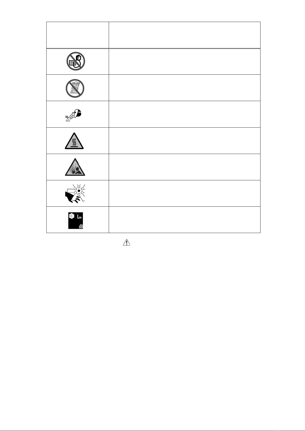
1. Safety Precautions ........................................................................................2
2. Specifications ................................................................................................8
3. Applications ...................................................................................................9
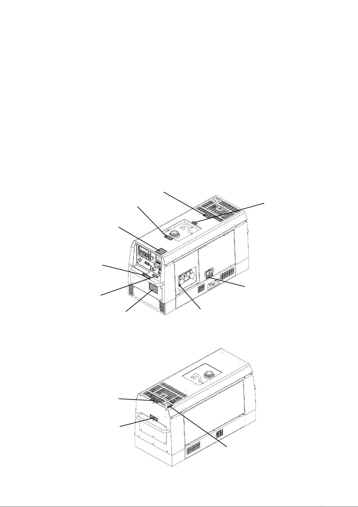
4. Parts Names...................................................................................................9
5. Equipment....................................................................................................12
5-1. Idle Control ...........................................................................................12
5-2. Display..................................................................................................12
5-3. Monitor Lamp .......................................................................................13
5-4. Earth Leakage Circuit Breaker and Grounding ....................................14
5-5. Emergency Stop Switch .......................................................................15
6. Transporting ................................................................................................16
7. Pre-Operation Inspection ...........................................................................16
7-1. Engine Oil Inspection ...........................................................................17
7-2. Coolant Inspection................................................................................17
7-3. Fuel Inspection .....................................................................................18
7-4. Inspection for Fuel/Oil/Cooling Water Leakage....................................19
7-5. Battery Inspection.................................................................................19
8. Operating Procedures.................................................................................20
8-1. Starting the Engine...............................................................................20
8-2. Stopping the Engine .............................................................................21
8-3. Emergency Stop...................................................................................22
9. Using as a Welder .......................................................................................22
9-1. Welding Cable Selection ......................................................................22
9-2. Welding Polarity ...................................................................................22
9-3. Welding Cable Connection...................................................................23
9-4. Duty Cycle ............................................................................................23
9-5. Welding Work .......................................................................................23
10. Using as a Generator ................................................................................24
10-1. Output Types and Ranges..................................................................24
10-2. Usable Device Capacities ..................................................................25
10-3. Operation............................................................................................25
11. Simultaneously Welding and Using as AC Power Source ....................26
12. Inspection/Maintenance............................................................................27
13. Long-Term Storage ...................................................................................31
14. Troubleshooting ........................................................................................32
15. Engine Wiring Diagram.............................................................................34
16. Generator Wiring Diagram........................................................................35

- 2 -
1. Safety Precautions
Warning: Suffocation from Exhaust Fume
Do not operate the equipment in a poorly-ventilated area such as indoors or within a
tunnel because the engine exhaust fume includes components that are harmful to
humans.
Warning: Suffocation from Welding Fume
Always be sure to wear a fume-proof mask when welding as the fumes generated
during welding include harmful gases and dust. Also be careful that the wind direction
is not such that it will cause fumes to be inhaled and always operate the equipment in
a well-ventilated area.
Warning: Electric Shock
Do not operate the equipment with any doors or covers open.
Do not touch wirings or any electric parts inside the equipment during operation.
Do not touch the equipment during operation if the equipment or your body is wet.
Be sure to stop the engine whenever touching Welding output terminals such as
when installing or removing welding cables.
Do not connect welding cables to any part other than Welding output terminals.
Do not insert any metallic objects, such as pins or wires, into AC output receptacles.
Always be sure to turn off all circuit breakers before installing or removing devices
using AC output receptacles.
Always be sure to repair the fault when the earth leakage circuit breaker operates.
Always be sure to stop the engine before performing any equipment check or
maintenance.
Warning: Fire
Always be sure to stop the engine when inspecting fuel or refueling, and absolutely
never perform such tasks near fire or other open flames or sparks. Wait until the
engine has completely cooled before inspecting fuel or refueling.
Always be sure to wipe away any spilled fuel or oil.
Absolutely never use the equipment if there is a fuel, oil or cooling water leak, and be
sure to always repair the leak before using.
Absolutely never inspect or perform maintenance to the equipment near fire or other
open flames or sparks.
Keep any ignitable items (such as fuel, gas and paint) or inflammable items away
from the equipment because the muffler, exhaust fume and other parts attain high
temperatures.
Keep any ignitable items (such as fuel, gas and paint) or inflammable items away
from the work area due to the scattering of weld spatter that occurs during welding.
Provide at least 1 meter (3 feet) of distance between the equipment and walls and
other obstacles, and operate the equipment on a flat surface.
Allow the equipment to cool before covering with protective covers and similar items.
Do not ground wiring of earth leakage circuit breakers of the equipment to piping that
contains through flammable material.

- 3 -
Warning: Injury
Do not operate the equipment with any doors or covers open. There is a danger of
hair, body parts and other items being caught up in moving parts such as cooling
fans and belts.
Do not modify the equipment and do not operate with parts removed.
Always be sure to stop the engine before performing any equipment check or
maintenance.
The lifting lug is designed to be used only for lifting the equipment. Do not lift the
equipment with any heavy items (such as a trailer, gas canister and additional fuel
tank) added to the equipment.
Warning: Injury to Eyes and Skin
Use protective gear, such as rubber gloves, when inspecting or replacing the battery
due to the dilute sulfuric acid in the battery fluid. Be sure that fluid does not contact
eyes, or on skin or clothing.
If battery fluid gets into the eyes, or on the skin or clothing, immediately wash with a
large amount of water, and always be especially sure to seek medical attention if it
gets into the eyes.
Warning: Explosion
Do not operate the equipment or recharge the battery when the battery fluid level is
below the lower level.
Do not generate any sparks near the battery and do not allow any fire or other open
flames near the equipment because the battery generates ignitable gas.
Warning: Electromagnetic Interference
Persons using a heart pacemaker are not allowed near the welder or welding work
area while welding is being performed without the permission of a doctor. The welder
generates a magnetic field while energized that can negatively affect pacemaker
operation.
Caution: Suffocation from Exhaust Fume
Do not direct the engine exhaust towards passersby, private homes or similar
persons/locations because the engine exhaust fume includes components that are
harmful to humans.
Caution: Electric Shock
Do not sprinkle water on the equipment and do not use where exposed to rain and
thunder.
If wearing gloves, be sure to always wear gloves with dry insulation properties. Do
not wear gloves that are damaged or wet.

- 4 -
Caution: Burn
The engine, muffler and similar parts are extremely hot during operation and
immediately after stopping the equipment. Never touch hot parts.
Never open the radiator cap during operation or immediately after stopping the
equipment. Hot cooling water and steam will spurt out.
Always be sure to stop the engine and allow it to cool before inspecting or changing
the engine oil. Opening the oil gauge or oil plug during operation will result in hot oil
spurting out.
Always be sure to wear leather gloves, apron, shoe covers, arc-proof glasses (face
shield), safety shoes, hard hat and long-sleeve clothing to protect against the
scattering of weld spatter that occurs during welding.
Caution: Injury
Use this equipment with it situated on a stable level surface so that it is prevented
from moving.
Do not move the equipment during operation.
Always be sure to turn off the switches of all devices using the equipment and turn off
the equipment circuit breakers before starting the engine.
Always be sure to turn off the power switches of all devices using the equipment
when turning on the equipment circuit breakers. Leaving on the power switch of a
device using the equipment when the equipment circuit breakers are turned on could
result in the sudden operation of the corresponding device.
Do not leave on the power switch of a device using the equipment and do not
connect a device to an AC output receptacle.
Always be sure to use the lifting lug when lifting the equipment, and lift slowly and
directly straight above.
Wear a helmet, safety shoes, gloves and similar protective gear when performing
lifting work. Do not stand or get under the equipment while it is suspended.
Securely fix the equipment with rope or similar item so that it cannot move when
transporting by truck or other vehicle.
Caution: Injury to Eyes and Skin
Always be sure to wear arc-proof glasses, clothes that completely cover the skin and
other protective gear when welding to protect the eyes and skin from harmful light
rays generated during welding.
Caution: Physical and Secondary Damage
Do not use the equipment for any improper applications. Improper usage can result
in an accident or malfunction.
Do not connect the AC power source to indoor wiring.
If using the equipment as a power source for medical equipment, you must check
with the medical equipment manufacturer, doctor and hospital before using the
equipment.
Caution: Damage to the equipment or other properties
Do not use anything other than the specified optional device because they may
cause malfunctions.

- 5 -
■Location of Warning Labels
Replace warning labels when they become difficult to see or damaged by affixing
new labels in the specified locations. Order the necessary labels by numbers in
parentheses.
① Suffocation from exhaust fumes (No. X505-011481)
② Electric shock (No. X505-011470)
③ Fire (No. X564-000640)
④ Injury (No. X564-000630)
⑤ Burn (No. X505-006410)
⑥ Lifting Eye (No. M707-000240)
⑦ Earth leakage relay (X505-004890)
⑧ Hot Surface (X505-011490)
⑨ Positioning Handle (X505-006430)
⑩ Keep 1 meter (No. M707-000260)
⑪Earth Symbol (No. M708-000890)
③
⑤
⑩
④
⑦
②
⑥
⑪
⑨
⑧
⑨
①

- 6 -
LABEL REPRODUCTION
① X505-011481
② X505-011470
③ X564-000640
④ X564-000630
⑤ X505-006410

- 7 -
⑥ X505-000240
⑦ X505-004890
⑧ X505-011490
⑨ X505-006430
⑩ M707-000260
⑪M708-000890

- 8 -
2. Specifications
Model
DGW300MS/UKV
Generating Method
Rotating Field
Welding DC Generator
Rated Current (A)
300
280
255
198
Rated Voltage (V)
32.0
31.2
30.2
27.2
Duty Cycle (%)
40
50
60
100
ECO
Current Adj. Range (A)
30 – 200
Welding Rod (φ)
2.0 – 5.0
AUTO
/ HIGH
Current Adj. Range (A)
40 – 300
Welding Rod (φ)
2.0 – 6.0
Rated Speed (min-1 )
3000
No Load Voltage (V)
MAX 85
Power source efficiency (%)
91
Idle state power consumption (W)
32
AC Generator
Rated Frequency (Hz)
50
Rated Speed (min-1 )
3000
Phase
1-Phase
3-Phase
Rated Voltage (V)
110 CTE
415
Rated Current (A)
30
9.8
Rated Output (kVA)
3.3
7.0
Power Factor
1.0
0.8
Rating
Continuous
Engine
Model
Kubota D722
Type
Vertical, Water-Cooled 4-Cycle Diesel Engine
Displacement (L)
0.719
Rated Output (kW/min-1)
14.0 / 3000
Fuel
EN standard or ASTM standard
(sulfur content < 15ppm)
Lubricant Oil
API Class CF or better (CJ excluded)
Lubrication Oil Volume (L)
3.8 (Effective 1.4)
Cooling Water Volume (L)
3.0 (Sub Tank Capacity 0.6 L included)
Starting Method
Starter Motor
CO2 Emission data
Non-road steady-state test cycle (g/kWh)
1019.8
Battery
46B24L (Japanese Industrial Standard)
Fuel Tank Capacity (L)
37
Dimen-
sion
Length (mm)
1410
Width (mm)
566
Height (mm)
760
Dry Weight (kg)
348
Noise (dB(A))
Sound pressure level LpA
73.4 (2006/42/EC, d = 1 m, h = 1.6 m, I2 = 290 A)
Measured sound power level LWA
90 (2000/14/EC, r = 4 m)
Uncertainly KWA
1
Guaranteed sound power level LWA
91 (2000/14/EC, r = 4 m)
91 (declared)(2000/14/EC, r = 4 m)
WELDING GENERATOR EN 60974-10 EMC classification Group 2 Class A

- 9 -
<Note>
This CO2 measurement results from testing over a fixed test cycle under laboratory
conditions a parent engine representative of the engine family and shall not imply or
express any guarantee of the performance of a particular engine.
3. Applications
Shielded Metal Arc Welding
Power Source for Light, Electric Tools and Appliances
Caution: Physical and Secondary Damage
Do not use the equipment for any applications not listed above. Improper usage can
result in an accident or malfunction.
If using the equipment as a power source for medical equipment, you must check
with the medical equipment manufacturer, doctor and hospital before using the
equipment.
4. Parts Names
Welding Output Terminals
Fuse
(10A,50A)
Front Panel Removed
Battery
Under Plate
Operation Panel

- 10 -
Display
Select
Switch
Display
Emergency
Stop Switch
1-P
110V Breaker
3-P ELCB
(415V Breaker)
1-P ELCB
Fuel Meter
Monitor Lamp
Starter
Switch
Side Door
Air Cleaner
Oil Gauge
Sub Tank
Oil Plug
Oil Inlet
Oil
Drain Plug
Fuel
Drain Plug
Water
Drain Plug
Fuel Lever
(Fuel Strainer)
3-P 415V
Receptacle
1-P 110V
Receptacle
Bonnet
Grounding
Terminal
Welding
Current Dial
Idle Control
Switch

- 11 -
Tool
Kit
Fuel Inlet
Lifting Lug
Positioning Handle
(Not to be used for lifting)
Owner’s and
Operator’s
Manual
Accessories
Starter Key
1 Set
Door Key
1 Set
Muffler
Top Plate
Positioning Handle
(Not to be used for lifting)
Oil Filter
Fixed Side Panel Removed

- 12 -
5. Equipment
5-1. Idle Control
The equipment includes an idle control function.
You can use the idle control switch to select an
engine speed setting of "ECO", "AUTO" or "HIGH".
(1) ECO Drive
The equipment includes an eco drive function in
order to reduce noise, save fuel, and reduce
exhaust gas emission.
When the idle control switch is set to "ECO" and only welding is being performed, the
engine operates at an optimal speed corresponding to the weld output and it
automatically returns to low speed when welding is stopped.
<Note>
If using as an AC power source during eco drive (including when welding and using
as an AC power source at the same time), the engine operates at high speed.
Set the idle control switch to "AUTO" or "HIGH" if welding or using as an AC power
source in an intermittent manner.
Set the idle control switch to "HIGH" if using a high capacity motor, precision
instruments or AC load with an attached magnetic switch.
Set the idle control switch to "HIGH" if using as an AC power source of a device of
0.5A or less because the engine might not reach a high speed as speed control does
not operate at that level.
(2) Auto Idle
The equipment includes an auto idle function in order to reduce noise, save fuel, and
reduce exhaust gas emission.
You can set the idle control switch to "AUTO" so that the engine operates at low speed
when not welding or using the equipment as a power source.
When you start to weld or use as an AC power source, the engine automatically
increases to high speed. When in a no-load condition, the engine automatically returns
to low speed after approximately 8 seconds of high-speed operation.
<Note>
Set the idle control switch to "HIGH" if using a high capacity motor, precision
instruments or AC load with an attached magnetic switch.
Set the idle control switch to "HIGH" if using as an AC power source of a device of
0.5A or less because the engine might not reach a high speed as speed control does
not operate at that level.
(3) High Idle
You can set the idle control switch to "HIGH" to maintain the engine constantly at high
speed.
5-2. Display
The equipment includes a digital display that displays the AC Voltage, Hours Worked
and Speed successively by changing the display select switch.
<Note>
During operation, the AC Voltage always displays the three phase 415V output
voltage regardless of whether the breaker is set to "ON" or "OFF".
Idle Control
Switch

- 13 -
5-3. Monitor Lamp
Warning: Injury/Electric Shock
Do not operate the equipment with any doors or covers open. There is a danger of
hair, body parts and other items being caught up in moving parts such as cooling
fans and belts.
Caution: Burn
The engine, muffler and similar parts are extremely hot during operation and
immediately after stopping the equipment. Never touch hot parts.
Never open the radiator cap during operation or immediately after stopping the
equipment. Hot cooling water and steam will spurt out.
Always be sure to stop the engine and allow it to cool before inspecting or changing
the engine oil. Opening the oil gauge or oil plug during operation will result in hot oil
spurting out.
The equipment includes monitor lamps for water
temperature, battery charge, oil pressure.
If the equipment is normal, the "CHARGE", "OIL PRESS"
monitor lamps illuminate when the starter switch is
switched to "STOP" to "RUN", and all monitor lamps turn
off when the engine is started. If any error occurs during
operation, the corresponding monitor lamp illuminates
and the engine is automatically stopped. If the engine is
automatically stopped, return the starter switch to "STOP"
and restart the engine. Watch the lit/unlit status of the
monitor lamps the next time an automatic stop occurs and
check the error contents.
(1) Water Temperature Monitor Lamp
The water temperature monitor lamp ("WATER TEMP") illuminates and the engine is
automatically stopped if the cooling water temperature becomes irregularly high during
operation. If this occurs, inspect the water level of the sub tank and add cooling water if
the water level is insufficient. (Refer to section "7-2 Cooling Water Inspection".)
If the cooling water in the sub tank is at the specified level, it is probable that
overloading is the cause. Use within the rated output.
(2) Battery Charge Monitor Lamp
The battery charge monitor lamp ("CHARGE") illuminates and the engine is
automatically stopped if battery charge fails during operation. If this occurs, it is
probable that there is fan belt damage or a wiring fault. Request repair at the retail
outlet where the equipment was purchased.
(3) Oil Pressure Monitor Lamp
The oil pressure monitor lamp ("OIL PRESS") illuminates and the engine is
automatically stopped if the engine oil pressure drops during operation. If this occurs,
inspect the engine oil level and fill with engine oil until it reaches the maximum level.
<Note>
The oil pressure monitor cannot detect oil deterioration. Change the engine oil
periodically. (Refer to section "12. Inspection/Maintenance".)
The charge monitor cannot detect battery deterioration or insufficient battery fluid.
Inspect the battery fluid level periodically. (Refer to section "7-5 Battery Inspection".)
Inspect the fuses if the engine is automatically stopped and none of the monitor lamps
("WATER TEMP", "CHARGE" and "OIL PRESS") illuminate. (Refer to section "4. Part
Names" for fuse location.)
If a fuse has blown, it is probable that there is a fault in an electric part or the wiring.
Request repair at the retail outlet where the equipment was purchased.
Battery
Charge
Water
Temp
Oil
Press

- 14 -
5-4. Earth Leakage Circuit Breaker and Grounding
Warning: Electric Shock
Always be sure to repair the fault when the earth leakage circuit breaker operates.
Warning: Fire
Do not ground wiring of earth leakage circuit breakers of the equipment to piping
that contains through flammable material.
The equipment includes earth leakage circuit breakers (solidly grounded type) in order
to prevent electric shock. Immediately isolate the electrical circuit if earth leakage
occurs due to insulation failure in devices using the equipment or similar reason.
(1) Bonnet Grounding Terminal
The equipment includes a bonnet grounding terminal in order to connect the grounding
rod. This machine bonnet grounding terminal should be grounded to the earth.
<Note>
Connect using a plug with a grounding pole.
If using a plug without a grounding pole, perform grounding work and check that used
devices are connected to ground.
Securely ground the bonnet grounding terminal to the metal frame of the vehicle if
transporting the equipment by truck or trailer.
In the event you cannot ground the generator to the earth, consult with the authorized
distributor or our dealer.
(2) Operation Check of Earth Leakage Circuit Breaker
Be sure to always check the earth leakage circuit breakers before starting operation
according to the following procedures.
1)Start the engine.
(Refer to section "8-1. Starting the Engine".)
2)Set the idle control switch to "HIGH".
3)Set the 1-P and 3-P ELCB lever to "ON".
4)Press the 3-P ELCB test button.
5)Operation is normal if the earth
leakage indicator button protrudes
and the lever is between the "ON"
and "OFF" position at this time.
6)Push down the 3-P ELCB lever to
the "OFF" position.
7)Press the 1-P ELCB test button.
Operation is normal if the White lever
and Black lever of the 1-P ELCB
lowers and turns off at this time.
There is a fault in the earth leakage circuit breakers if operation cannot be checked
according to the above procedures. Request repair at the retail outlet where the
equipment was purchased.
Bonnet
Grounding
Terminal
Grounding
Rod
Idle Control
Switch
Bonnet
Grounding
Terminal
3-P ELCB
1-P ELCB
Test
Button
Earth
Leakage
Indicator
Button
Test
Button
White Lever
And
Black Lever

- 15 -
(3) If an Earth Leakage Circuit Breaker Operates
Caution: Electric Shock/Injury
Always be sure to turn off the power switches of all devices using the equipment
when turning on the equipment circuit breakers after an earth leakage circuit
breaker operates. Leaving on the power switch of a device using the equipment
when the equipment circuit breakers are turned on could result in the sudden
operation of the corresponding device.
The leakage indication button will protrude and the 3-P ELCB lever is between the
"ON" and "OFF" position when 3-P ELCB operates.
The White lever and Black lever of 1-P ELCB moves to "OFF" when 1-P ELCB
operates.
When this occurs, immediately stop the engine and repair the earth leakage location.
After repairing all faults, push up the 1-P ELCB lever to the "ON" side to reset the
system. For 3-P ELCB, push breaker lever down to "OFF" and push up the lever to the
"ON".
<Note>
If the 3-P ELCB Leakage indication button does not protrude or the 1-P ELCB (only
Black lever) turns to OFF, it means AC Output over load.
5-5. Emergency Stop Switch
Press the emergency stop switch to stop the engine immediately.
After pressing the emergency stop switch, securely return the
starter switch to the "STOP" position and turn the emergency
stop switch clockwise to reset the switch.
Stop
Reset
Table of contents
Other Shindaiwa Engine manuals

Shindaiwa
Shindaiwa DGM60MK User manual

Shindaiwa
Shindaiwa DGW400DMK User manual

Shindaiwa
Shindaiwa DG1000MIM User manual

Shindaiwa
Shindaiwa DGW400DML User manual

Shindaiwa
Shindaiwa DG1000MI User manual

Shindaiwa
Shindaiwa DGW200MS/UKV User manual

Shindaiwa
Shindaiwa DG15BMK User manual

Shindaiwa
Shindaiwa DGW310MC User manual

Shindaiwa
Shindaiwa M262 User manual