3
Provide at least 1 meter (3 feet) of distance between the equipment and walls and other
obstacles, and operate the equipment on a flat surface.
Allow the equipment to cool before covering with protective covers and similar items.
Do not ground wiring of earth leakage circuit breakers of the equipment to piping that
contains flammable material.
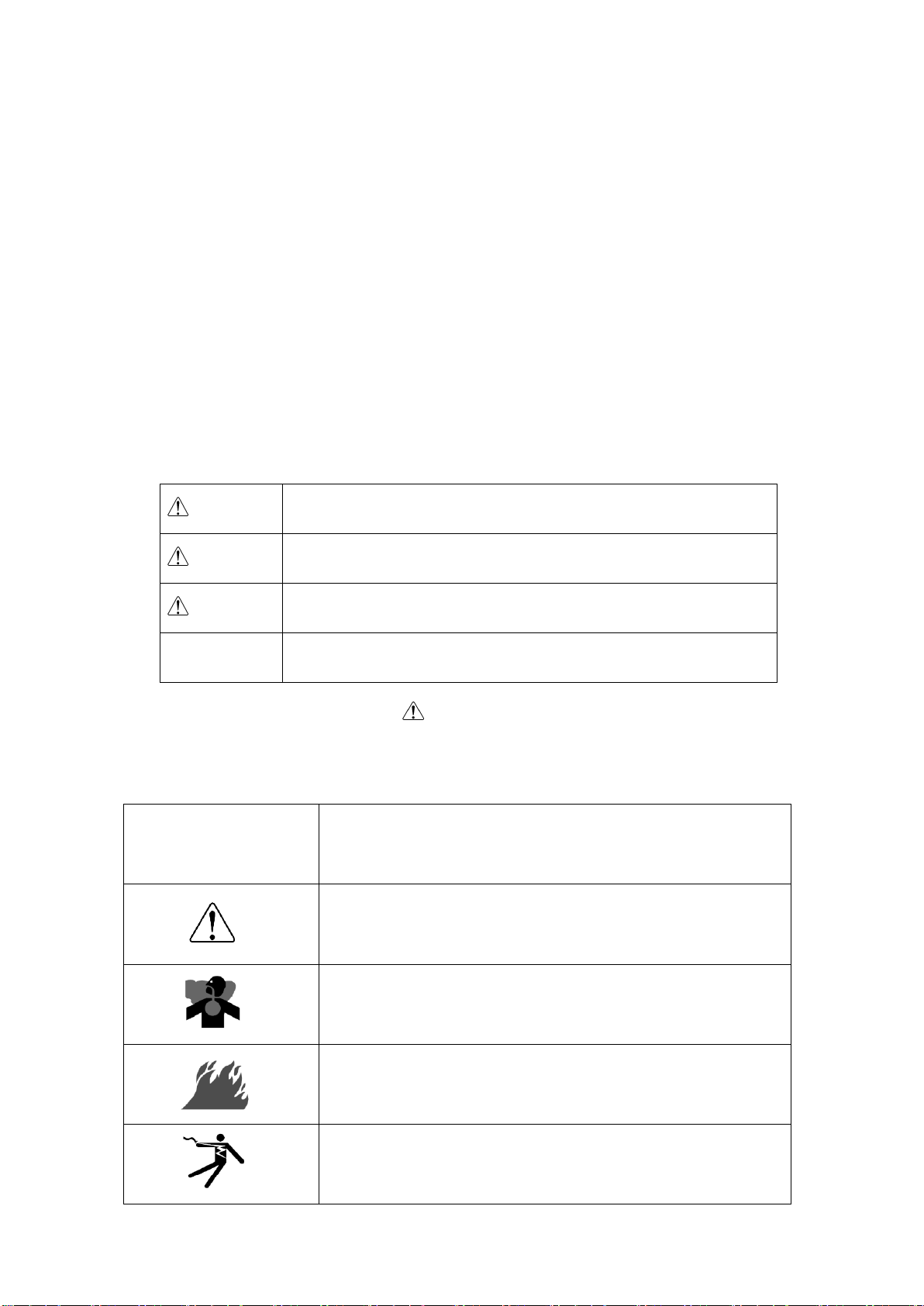
Warning: Injuries
Do not operate the equipment with any doors or covers open, and always lock them.
There is a danger of hair, body parts and other items being caught up in moving parts
such as cooling fans and belts.
Do not modify the equipment and do not operate with parts removed.
Always be sure to stop the engine and remove the starter key before performing any
equipment check or maintenance. The person performing the maintenance must always
keep the key.
Do not lift up by positioning handle. Doing so could cause the generator to fall.
No persons should ever be under a lifted generator.
Warning: Explosion
Do not operate the equipment or recharge the battery when the battery fluid level is
below the lower level.
Do not generate any sparks near the battery and do not allow any fire or other open
flames near the equipment because the battery generates ignitable gas.
Warning: Electromagnetic Interference
Persons using a heart pacemaker are not allowed near the Generator work area while
the Generator is in operation without the permission of a doctor. The welder generates a
magnetic field while energized that can negatively affect pacemaker operation.
Caution: Electric Shock
Do not come in contact with the output terminals while this equipment is in operation.
Turn the main circuit breaker to off and stop the engine before servicing.
Do not connect the AC output to indoor wiring.
Do not splash water onto the equipment or operate it in the rain.
If wearing gloves, be sure to always wear gloves with dry insulation properties.
Do not wear gloves that are damaged or wet.
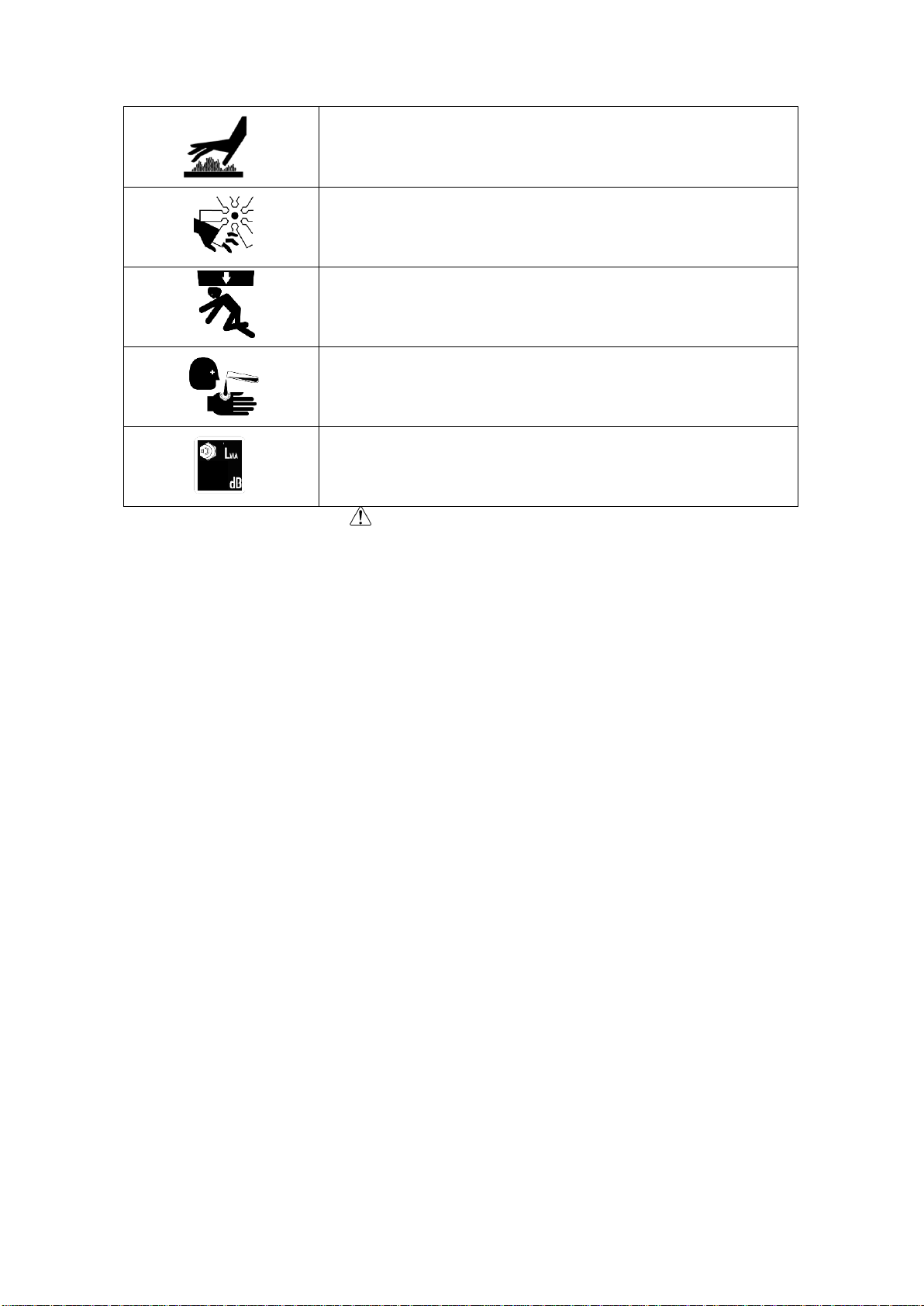
Caution: Burns
The engine, muffler and similar parts and surrounding components are extremely hot
during operation and immediately after stopping the equipment. Never touch hot parts.
Never open the radiator cap during operation or immediately after stopping the
equipment. Hot coolant and steam will spurt out.
Always be sure to stop the engine and leave the engine to cool down before performing
any inspection/maintenance such as inspection of engine oil or fuel filter. Opening the oil
level gauge or oil filler during operation will result in hot oil spurting out.
Caution: Injuries to Eyes and Skin
Use protective gear, such as rubber gloves, when inspecting or replacing the Battery acid,
Diesel fuel and/or Engine oil. Be sure that fluid does not contact eyes, or on skin or
clothing.