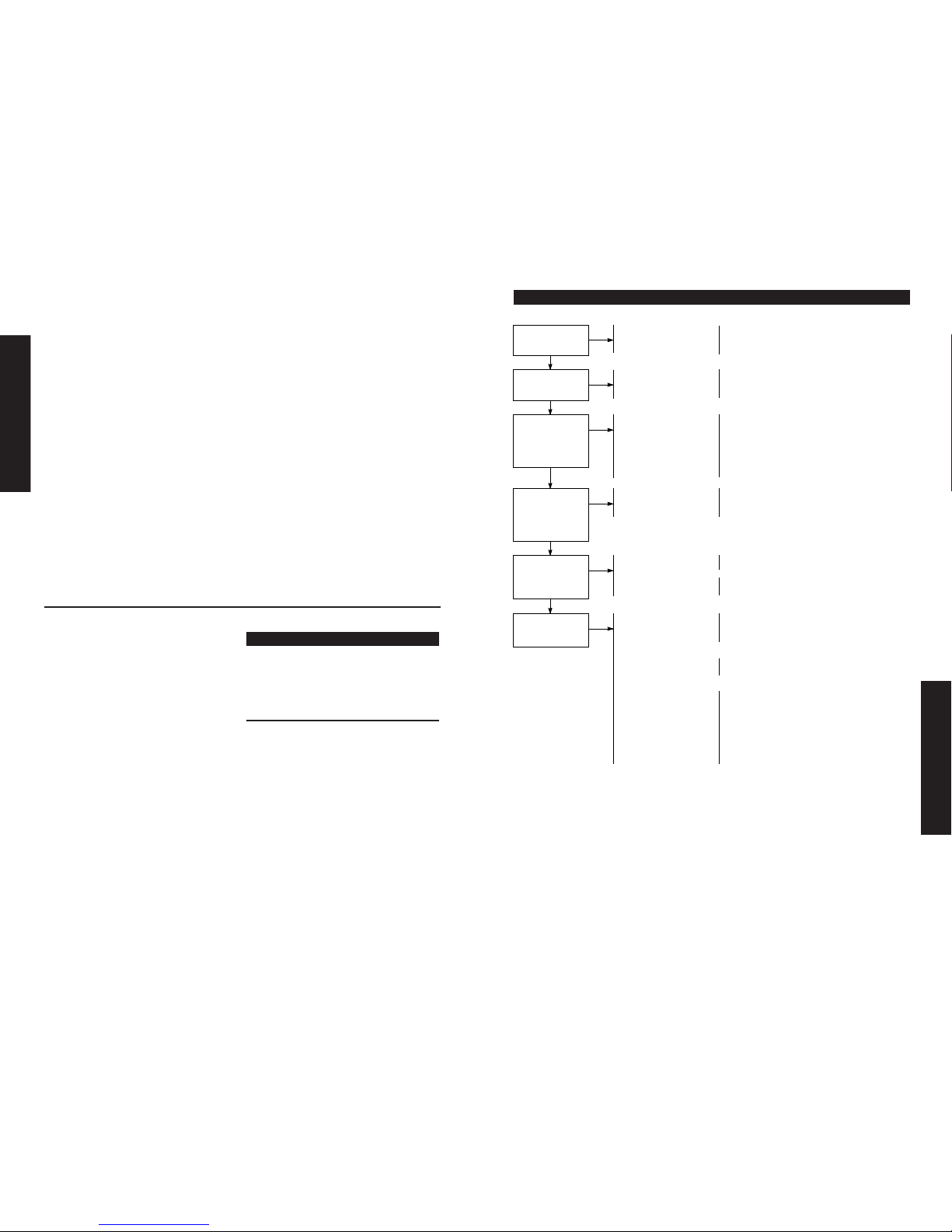
Throughout this manual are special
“attention statements”.
WARNING!
A statement preceded by the
triangular attention symbol and the
word “WARNING” contains
information that should be acted
upon to prevent serious bodily
injury.
CAUTION!
A statement preceded by the word
“CAUTION” contains information
that should be acted upon to
prevent mechanical damage.
IMPORTANT!
The operational procedures described
in this manual are intended to help
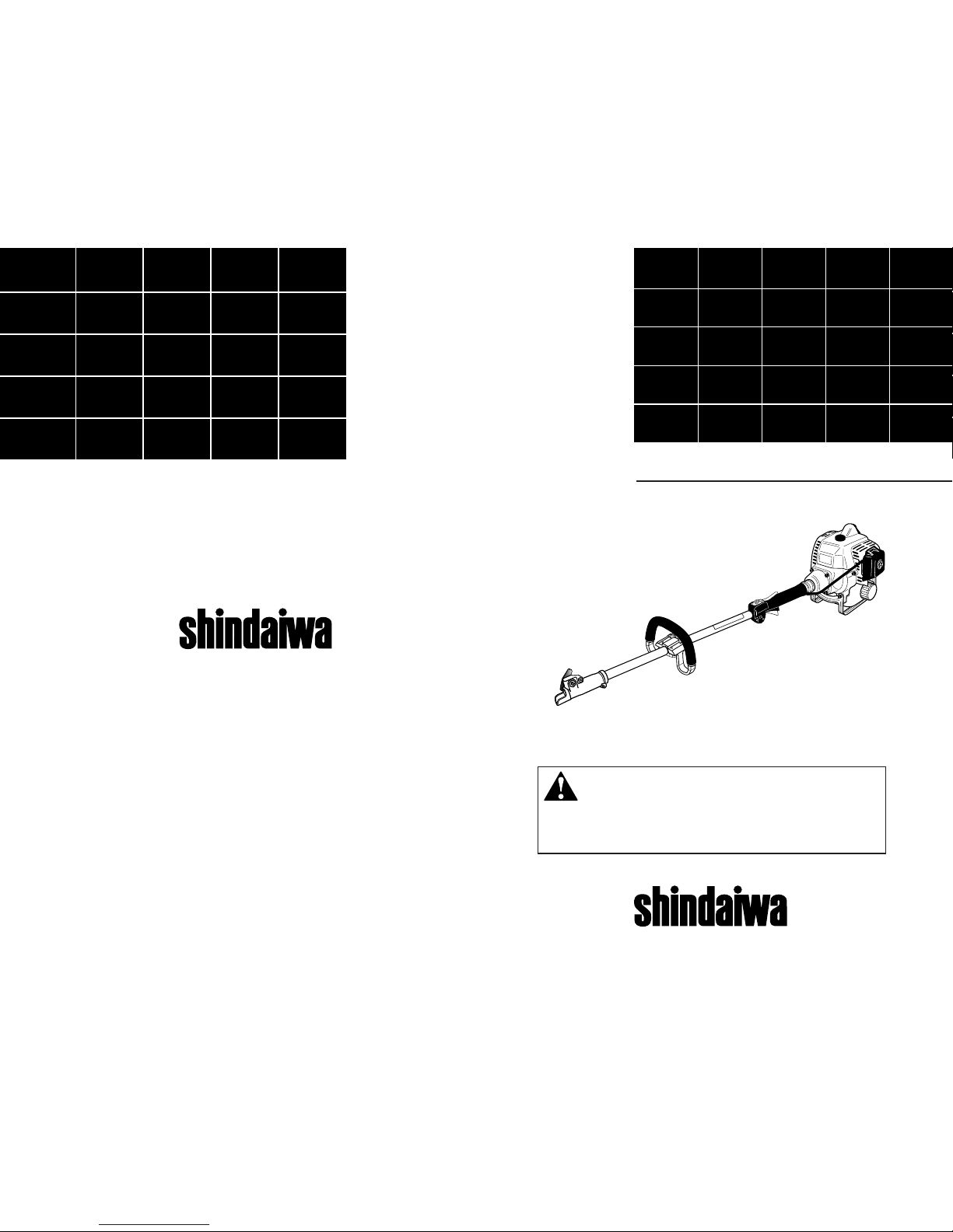
you get the most from your M230
Multipurpose Tool Carrier as well as
to protect you and others from harm.
These procedures are guidelines for
safe operation under most conditions,
and are not intended to replace any
safety rules and/or laws that may be
in force in your area. If you have
questions regarding your 230-series
power tool, or if you do not under-
stand something in this manual, your
Shindaiwa dealer will be glad to assist
you. You may also contact Shindaiwa,
Inc. at the address printed on the back
of this Manual.
Attention Statements
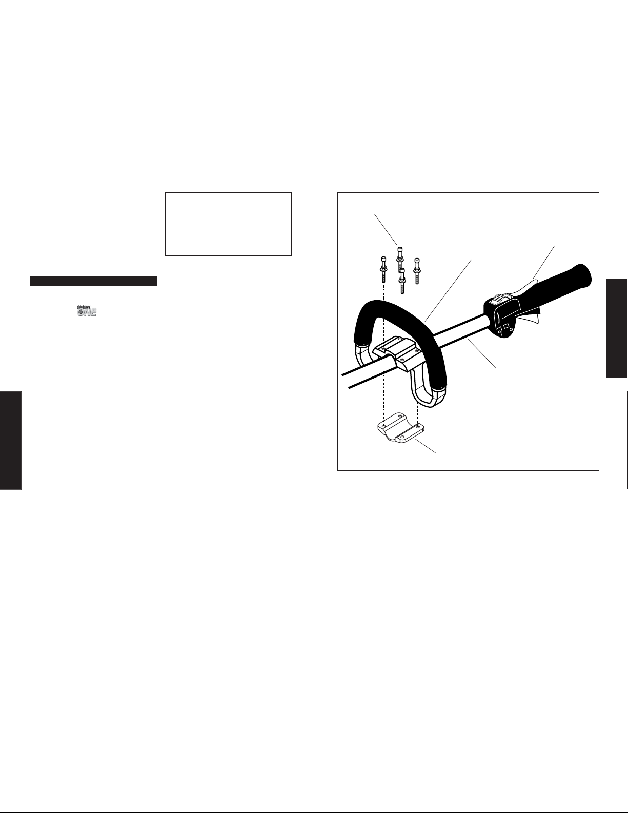
SAFETY
2
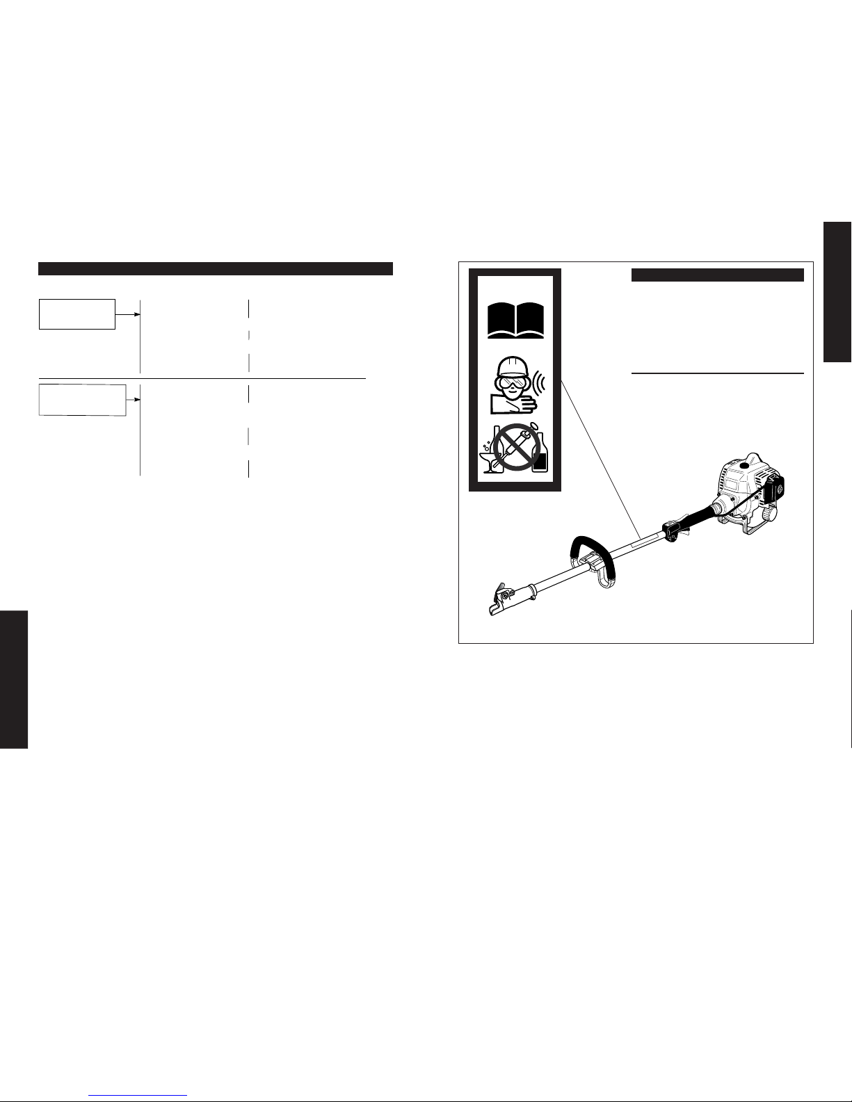
Read and follow this
manual. Failure to do
so could result in
serious injury.
Wear eye and hearing
protection at all times
during the operation
of this unit.
Keep bystanders
at least 50 Feet (15 m)
away during operation.
Beware of thrown or
ricocheted objects.
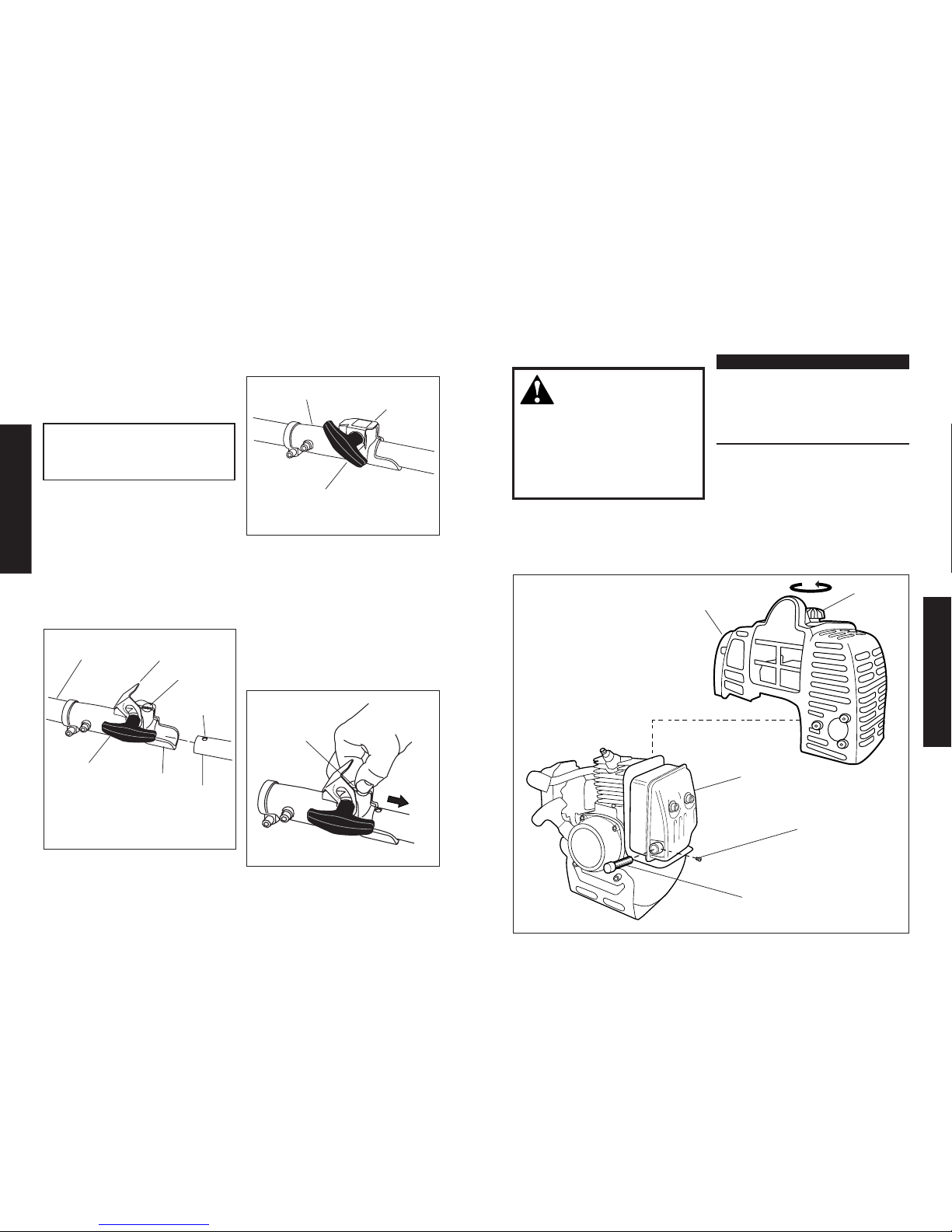
IMPORTANT!
A statement preceded by the word
“IMPORTANT” is one that possesses
special significance.
NOTE:
A statement preceded by the word
“NOTE” contains information that is
handy to know and may make your
job easier.
Shindaiwa Kogyo Co., Ltd.
Federal Emission Design And Defect Limited Warranty
Utility And Lawn And Garden Engines
Shindaiwa Kogyo Co., Ltd. warrants to the initial purchaser and each subsequent owner, that this
utility equipment engine (herein engine) is designed, built and equipped to conform at the time of
initial sale, to all applicable regulations of the U.S. Environmental Protection Agency (EPA), and
that the engine is free of defects in materials and workmanship that would cause this engine to fail
to conform with EPA regulations during its warranty period. This emission warranty is applicable in
all States, except the State of California.
For parts listed under PARTS COVERED, the dealer authorized by Shindaiwa Kogyo Co., Ltd.
will, at no cost to you, make the necessary diagnosis, repair, or replacement of any defective
emission-related component to ensure that the engine complies with applicable U.S. EPA regula-
tions.
MANUFACTURERS WARRANTY COVERAGE
When sold within the U.S., this engine’s emission control system is warranted for a period of two
(2) years from the date this product is first delivered to the original retail purchaser.
OWNER’S WARRANTY RESPONSIBILITIES
As the engine owner, you are responsible for the performance of the required maintenance listed
in your owner’s manual. Shindaiwa Kogyo Co., Ltd. recommends that you retain all receipts
covering maintenance on your engine, but Shindaiwa Kogyo Co., Ltd. cannot deny a warranty claim
solely for the lack of receipts or for your failure to ensure the performance of all scheduled
maintenance.
As the engine owner, you should however be aware that Shindaiwa Kogyo Co., Ltd. may deny
your warranty coverage if your engine or a part has failed due to abuse, neglect, improper
maintenance or unapproved modifications.
You are responsible for presenting your engine to the nearest dealer authorized by Shindaiwa
Kogyo Co., Ltd. when a problem exists.
If your Shindaiwa Dealer is unable to answer questions regarding your warranty rights and
responsibilities, you should then contact your Shindaiwa Distributor.
For the name and telephone number of the Shindaiwa Distributor in your area, please call
Shindaiwa Inc. at (503) 692-3070 between the hours of 8:00 AM and 5:00 PM Pacific Standard Time.
PARTS COVERED
Listed below are the parts covered by the Federal Emission Design and Defect Warranty. Some
parts listed below may require scheduled maintenance and are warranted up to the first scheduled
replacement of that part. The warranted parts include:
1. Carburetor Internal Components
• Valve Assembly-throttle, Jet, Metering Diaphram
2. Ignition System Components
• Ignition Coil
• Flywheel Rotor
The emission control system for your particular Shindaiwa engine may also include certain related
hoses and connectors.
LIMITATIONS
The Federal Emission Design and Defect Warranty shall not cover any of the following:
(a) conditions resulting from tampering, misuse, improper adjustment
(unless they were made by the dealer or service center authorized by
Shindaiwa Kogyo Co., Ltd. during a warranty repair), alteration, accident, failure to use the
recommended fuel and oil, or not performing required maintenance services,
(b) the replacement parts used for required maintenance services,
(c) consequential parts used for required maintenance services,
(d) diagnosis and inspection fees that do not result in eligible warranty
service being performed, and
(e) any non-authorized replacement part, or malfunction of authorized
parts due to use of non-authorized parts.
The following statement only applies to United States and its territories
25