Throughout this manual are special
“attention statements”.
IMPORTANT!
The operational procedures described in
this manual are intended to help you get
the most from this unit as well as to
protect you and others from harm.
These procedures are guidelines for
safe operation under most conditions,
and are not intended to replace any
safety rules and/or laws that may be in
force in your area. If you have questions
regarding your 2500-series hand held
power equipment, or if you do not
understand something in this manual,
your Shindaiwa dealer will be glad to
assist you. You may also contact
Shindaiwa, Inc. at the address printed
on the back of this Manual.
Attention StatementsIntroduction
PAGE
The Shindaiwa 2500-series hand held
power equipment has been designed
and built to deliver superior perfor-
mance and reliability without compro-
mise to quality, comfort, safety or
durability.
Shindaiwa engines represent the
leading edge of high-performance
engine technology, delivering excep-
tionally high power with remarkably low
displacement and weight. As an owner/
operator, you’ll soon discover for
yourself why Shindaiwa is simply in a
class by itself!
Shindaiwa Inc. reserves the right to
make changes to products without
prior notice, and without obligation to
make alterations to units previously
manufactured.
Attention Statements........................... 2
Safety Information ............................... 2
Safety Labels ........................................ 2
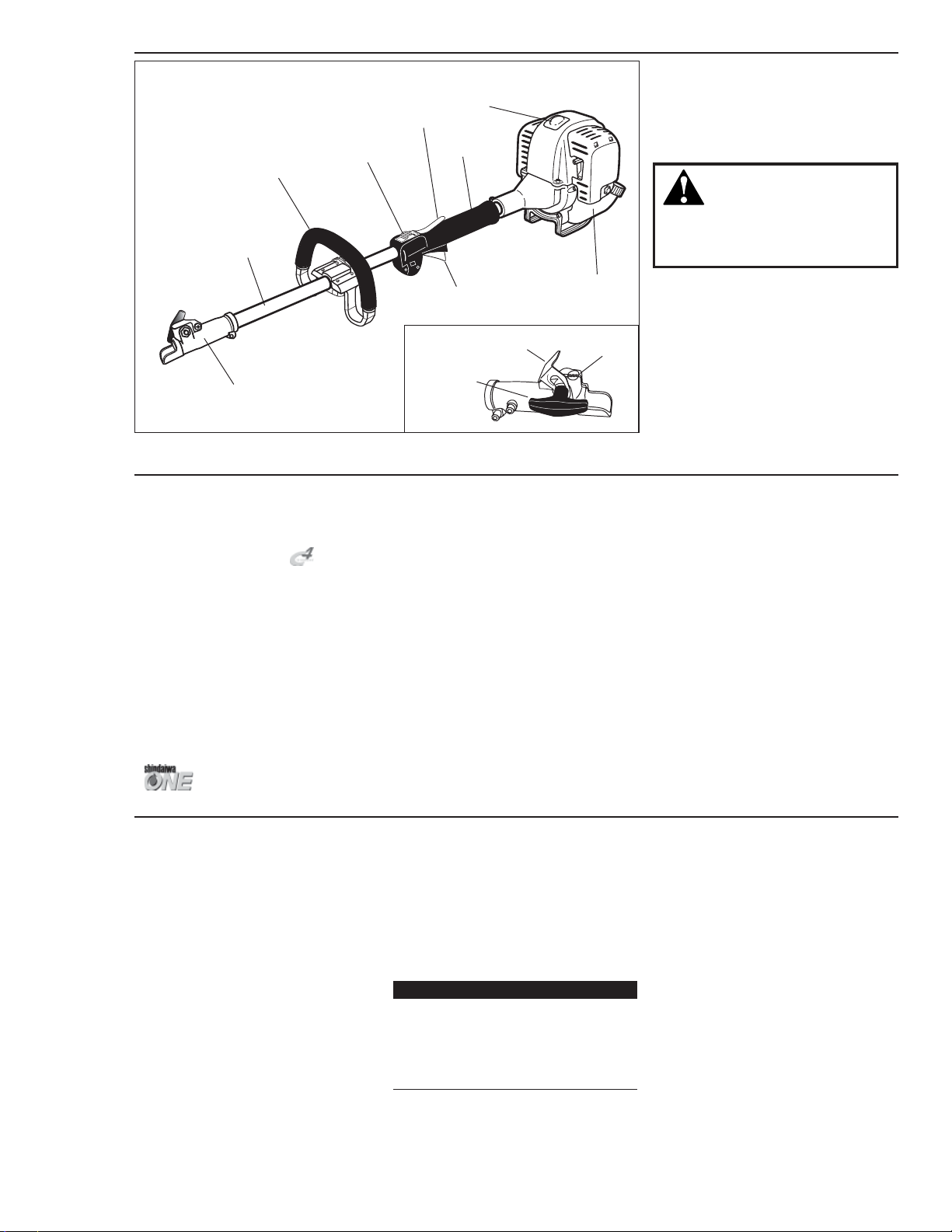
Product Description ............................ 4
Specifications ....................................... 4
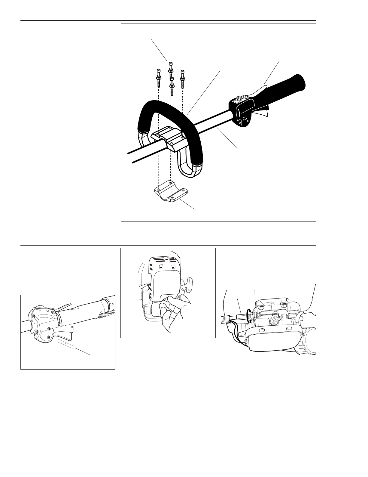
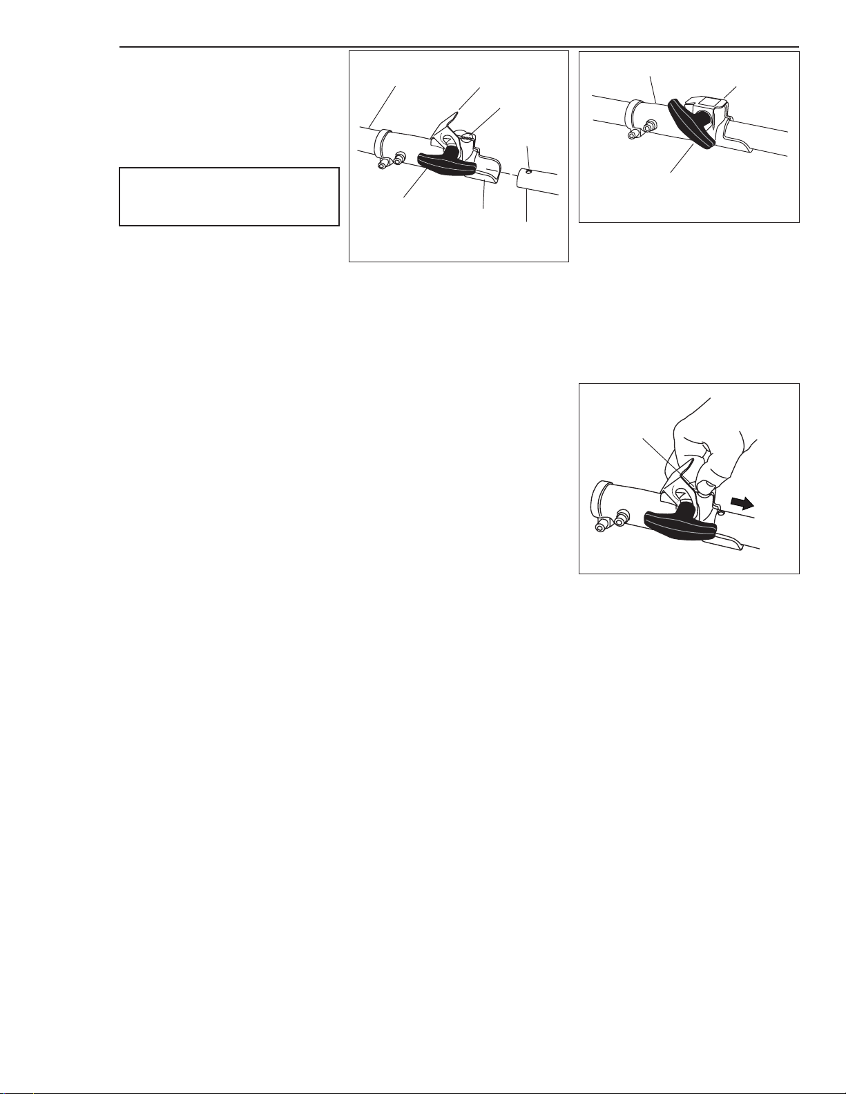
Assembly and Adjustments ................ 5
Installing a Tool Attachment .............. 6
Engine Fuel .......................................... 7
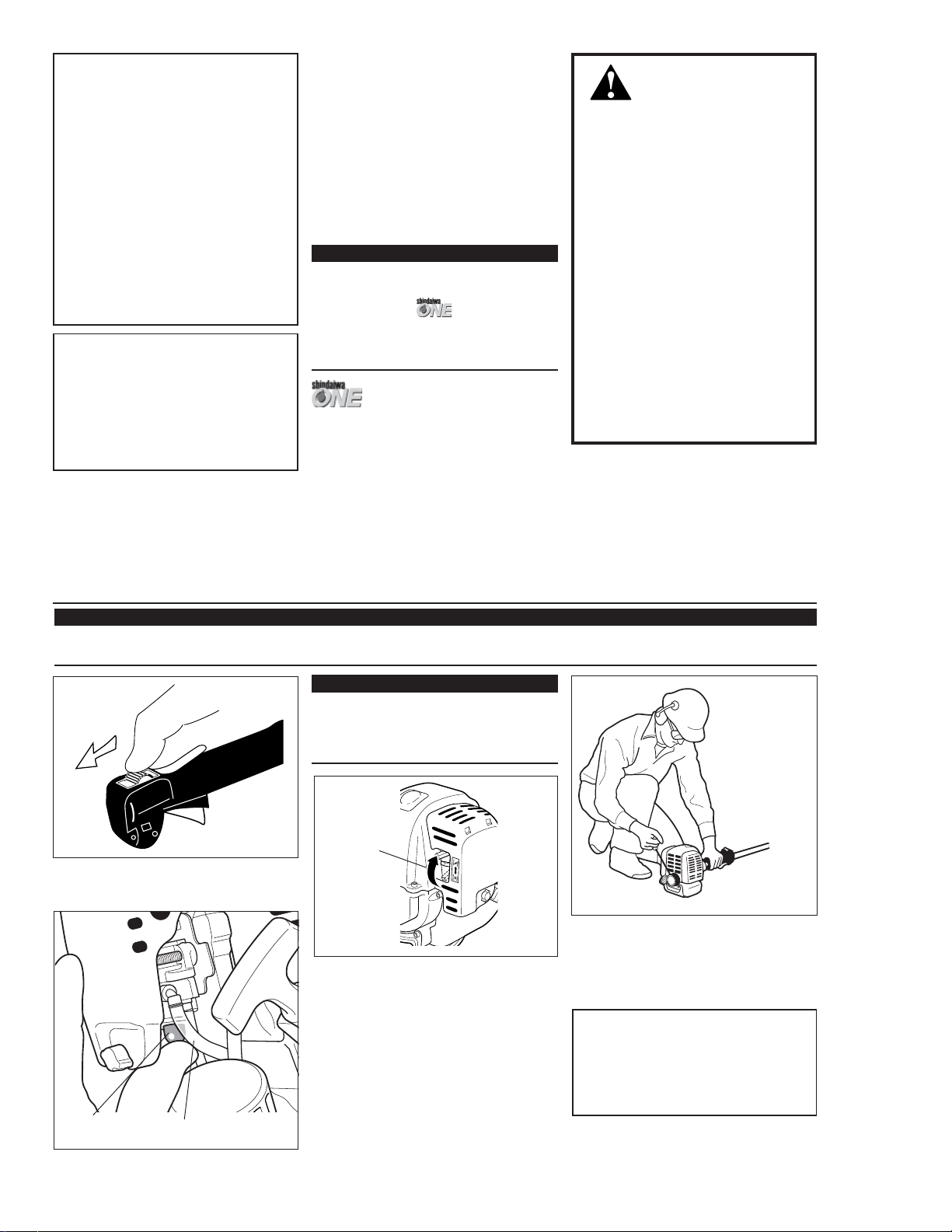
Starting the Engine ............................. 7
Stopping the Engine............................ 8
Adjusting Engine Idle ......................... 8
Checking Unit Condition.................... 9
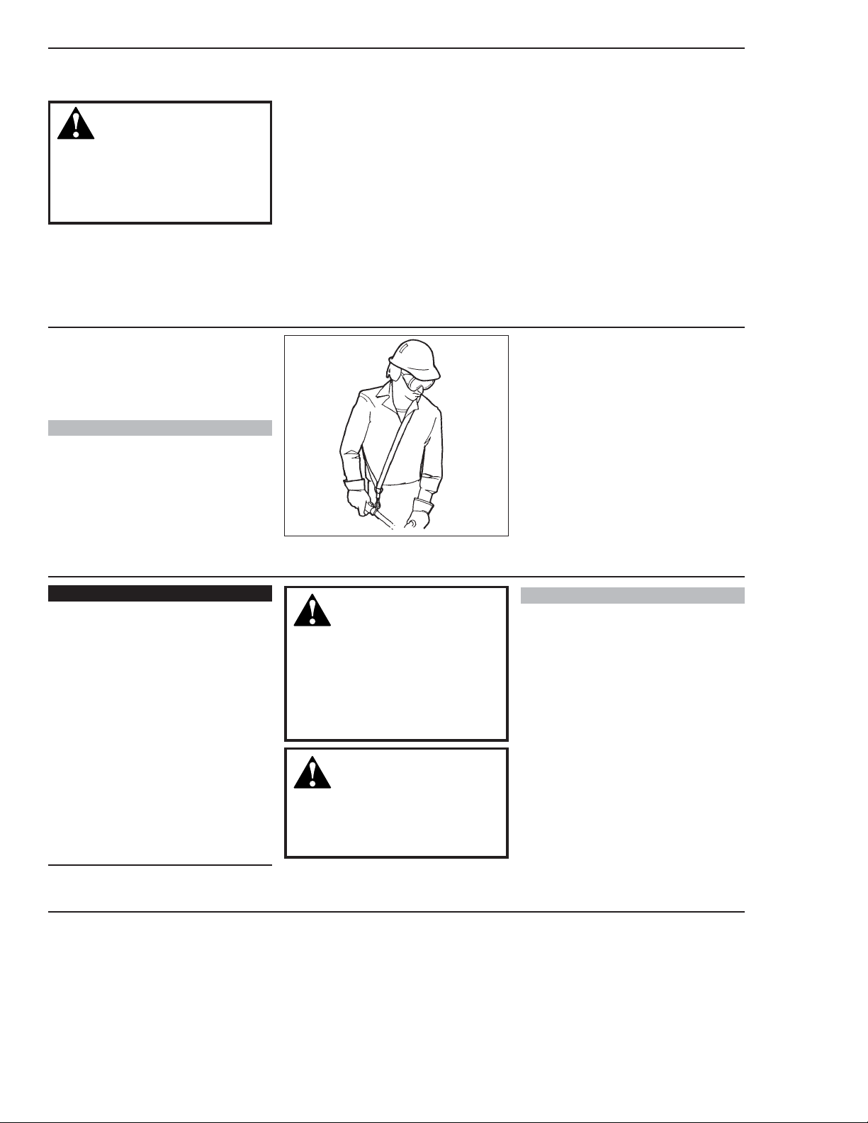
Shoulder Strap ...................................... 9
Maintenance ........................................ 9
Long Term Storage ........................... 11
Troubleshooting Guide .................... 12
Emission System Warranty...............14
Contents
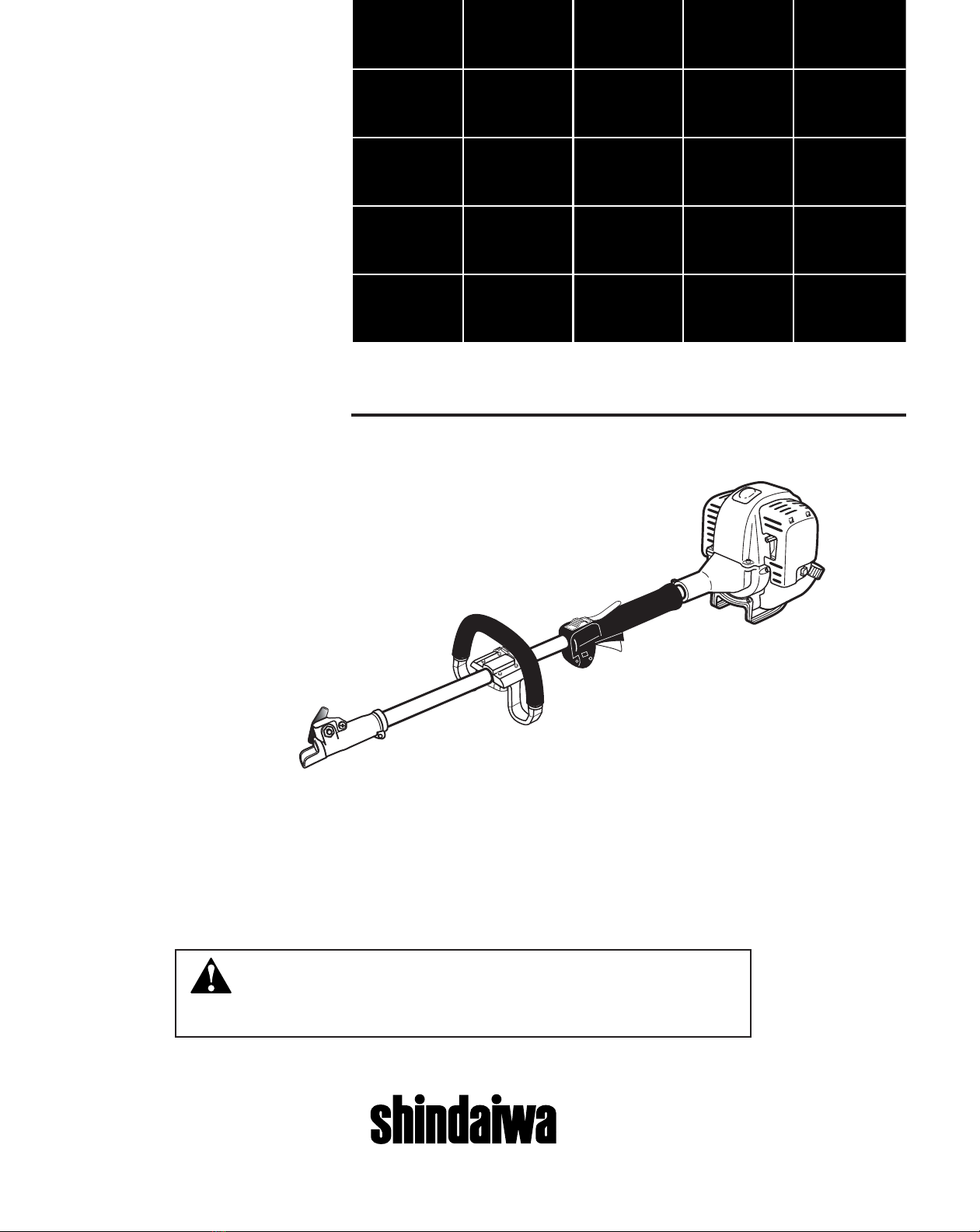
IMPORTANT!
The information contained in this
owner's/operator's manual describes
M2500 Multipurpose Tool Carrier
available at the time of publication.
CAUTION!
A statement preceded by the word
“CAUTION” contains information
that should be acted upon to prevent
mechanical damage.
WARNING!
A statement preceded by the
triangular attention symbol and the
word “WARNING” contains informa-
tion that should be acted upon to
prevent serious bodily injury.
Work Safely
Attachments for the Multipurpose Tool
Carrier operate at very high speeds and
can do serious damage or injury if they
are misused or abused. Never allow a
person without training or instruction
to operate this unit!
Stay Alert
You must be physically and mentally fit
to operate this unit safely.
General Safety Instructions
WARNING!
WARNING!
Never operate power equipment of
any kind if you are tired or if you are
under the influence of alcohol,
drugs, medication or any other
substance that could affect your
ability or judgement.
WARNING!
Minimize the Risk of Fire
NEVER smoke or light fires near
the engine.
ALWAYS stop the engine and allow
it to cool before refueling. Avoid
overfilling and wipe off any fuel that
may have spilled.
ALWAYS inspect the unit for fuel
leaks before each use. During each
refill, check that no fuel leaks from
around the fuel cap and/or fuel
tank. If fuel leaks are evident, stop
using the unit immediately. Fuel
leaks must be repaired before
using the unit.
ALWAYS move the unit to a place
well away from a fuel storage area
or other readily flammable materials
before starting the engine.
NEVER place flammable material
close to the engine muffler.
NEVER operate the engine without
the spark arrester screen in place.
KEEP the unit away from excessive
heat. Engine fuel is very flammable
and fire could lead to serious
personal injury or property damage.
Never make unauthorized
attachment installations. Do not use
attachments not approved by
Shindaiwa for use on this unit.
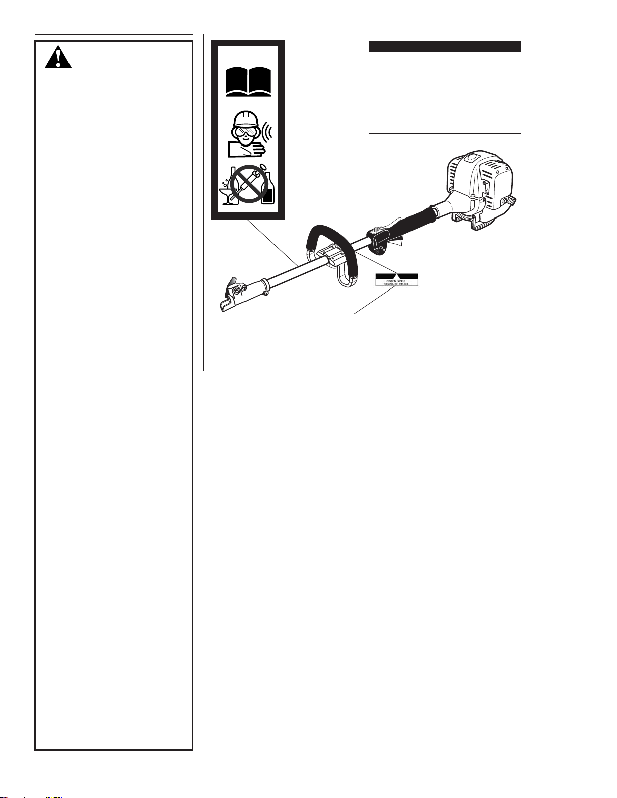
Do not operate this
unit with a blade.
Read and follow this
operators manual.
Failure to do so could
result in serious injury.
Wear eye and hearing
protection at all times
during the operation
of this unit.
Keep bystanders
at least 50 feet (15 m)
away during operation.
Beware of thrown or
ricocheted objects.
WARNING!
The engine exhaust from this
product contains chemicals known
to the State of California to cause
cancer, birth defects or other
reproductive harm.
NOTE:
A statement preceded by the word
“NOTE” contains information that is
handy to know and may make your
job easier.
IMPORTANT!
A statement preceded by the word
“IMPORTANT” is one that possesses
special significance.
2
No opere esta unidad
con un disco/cuchilla.
Lea y siga las
recomendaciones de este
manual del operario.
De no hacerlo podria
resultar en lesiones graves.
Use proteccion para los
ojos y proteccion para
los oidos en todo momento
que este operando esta maquina.
Mantenga a los transeuntes a
una distancia minima de 15
metros (50 pies) mientras la
maquina este en operacion.
Mantengase alerta por
objetos lanzados o rebotes.
A travéz de este manual se encuentran
“declaraciones de seguridad” especiales.
IMPORTANTE!
El propósito de los procedimientos
operacionales descritos en este manual
es ayudarle a obtener el más alto
rendimiento de su máquina y proteger a
usted y a otras personas de sufrir
lesiones. Estos procedimientos son
pautas operativas para una operación
segura bajo la mayoría de condiciones y
no tienen el propósito de substituir las
normas y/o leyes vigentes en su área.
Si tiene alguna pregunta relacionada con
la Serie 2500 de maquinaria manual o si
no entiende alguna información
contenida en este manual, consulte a su
distribuidor Shindaiwa, quien le
atenderá con gusto. También puede
comunicarse con Shindaiwa Inc. a la
dirección que aparece en la contra
portada de este manual.
Declaraciones De
Seguridad
Introducción
Página
La Serie 2500 de maquinaria manual
Shindaiwa, ha sido disenada y
construida para suministrar un
rendimiento superior sin comprometer
calidad, comodidad ni durabilidad.
Los motores Shindaiwa representan
la technologia lider de motores de alto
rendimiento, con excepcional alta
potencia de peso y cilindrada
sumamente bajos. Como proprietario/
operario, usted no tardara en comprobar
que Shindaiwa es la unica maquina en
esta clase!
Shindaiwa Inc. se reserva el derecho
de realizar cambios a sus productos sin
previo aviso, y sin la obligación de hacer
modificaciones a máquinas fabricadas
previamente.
Declaraciones de seguridad ............... 2
Información de seguridad .................. 2
Etiquetas de seguridad ....................... 2
Descripción del producto .................. 4
Especificaciones .................................. 4
Ensamblaje y Ajustes .......................... 5
Instalacion de una herramienta
accesorio............................................... 6
Combustible ......................................... 7
Arranque del motor ............................ 7
Parada del motor ................................. 8
Ajuste de marcha mínima ................... 8
Verificación de la condición
de la unidad .......................................... 9
Correa de arnés ................................... 9
Mantenimiento .................................... 9
Almacenamiento de largo plazo ...... 11
Guia diagnóstico ................................ 12
Garantía del sistema de emisiones .. 14
CONTENIDO
IMPORTANTE!
La información contenida en este
manual del proprietario/operario
describe la Porta Herramienta Multiple
M2500 disponibles a la fecha de
su publicación.
Precaución!
Toda información precedida por la
palabra PRECAUCION! contiene
información que se debe cumplir
para evitar daños mecánicos.
Toda información precedida por un
símbolo triangular de advertencia y
la palabra ADVERTENCIA! contiene
información o procedimientos que se
deben cumplir para evitar lesiones.
Trabaje con cuidado
Los accesorios para la porta
herramienta multiple operan a
velocidades altas y pueden causar daños
o lesiones serias si son malusadas o
abusadas. Nunca permita que una
persona sin entrenamiento o instrucción
opere esta unidad !
Mantengase Alerta
Debe de estar físicamente y
mentalmente en forma para operar esta
máquina con seguridad.
Instrucciones Generales
de Seguridad
Nunca opere ninguna máquinaria
motorizada si está cansado o si
está bajo la influencia de alcohol,
drogas o medicamentos o cualquier
otra substancia que pueda afectar
su abilidad y juicio.
Disminuya El Riesgo de
Incendios
NUNCA fume ni encienda fuegos
cerca del motor.
SIEMPRE pare el motor y permita
que se enfrie antes de volver a
llenar el tanque. Evite sobre llenar
el tanque y limpie cualquier derram
e de combustible.
SIEMPRE: Inspeccione la máquina
por pérdidas de combustible, antes
de cada uso. Durante cada llenado,
verifique posibles pérdidas
alrededor de la tapa o tanque de
combustible. Si existen pérdidas de
combustible evidentes, para
inmediatamente de utilizar la
máquina. Pérdidas de combustible
deben de ser reparadas antes de
cada uso.
SIEMPRE aleje la máquina del área
de combustible o de otros
materiales inflamables antes de
arrancar el motor.
NUNCA coloque materiales
inflamables cerca del silenciador de
la máquina.
NUNCA opere el motor sin la malla
del guardachispas en su lugar.
MANTENGA la unidad fuera del
calor excesivo. El combustible es
sumamente inflamable y un incendio
puede conducir a serias lesiones
personales o danos de propiedad.
Nunca instale accesorios no
autorizados. No use accesorios
no aprobados por Shindaiwa en
esta unidad.
Las emisiones emitidas por el tubo
de escape de este producto
contienen substancias químicas que
en el estado de California son
consideradas como causantes de
cáncer, defectos congénitos u
otros efectos nocivos a la
reproducción humana.
NOTA:
Toda información precedida por la
palabra “NOTA” contiene información
útil que puede hacer su trabajo
más fácil.
IMPORTANTE!
Toda información precedida por la
palabra “IMPORTANTE” contiene
información especial y significante.
2
¡Advertencia!
¡Advertencia!
¡Advertencia!
¡Advertencia!
¡Advertencia!