Shindaiwa M230 EMC Owner's manual

SHINDAIWA OWNER’S/OPERATOR’S MANUAL
M230 MULTIPURPOSE
TOOL CARRIER
M230
Part Number 65028-94310 Rev. 8/07
Read this manual and familiarize yourself with its contents.
This machine is designed for cutting grass, weeds and brush. Use only for
designated purpose.
Minimize the risk of injury to yourself and others.
Always wear eye protection when operating this machine.
Do not operate or service this machine unless you clearly understand
this manual.
Keep this manual available at all times so that you can reference it
whenever you have a question about the use of this unit.
■
■
■
■
■
■
WARNING!

2
Throughout this manual are special
“attention statements”.
IMPORTANT!
The operational procedures described
in this manual are intended to help you
get the most from this unit as well as
to protect you and others from harm.
These procedures are guidelines for safe
operation under most conditions, and are
not intended to replace any safety rules
and/or laws that may be in force in your
area. If you have questions regarding your
230-series hand held power equipment,
or if you do not understand something in
this manual, your Shindaiwa dealer will be
glad to assist you. You may also contact
Shindaiwa, Inc. at the address printed on
the back of this manual.
Attention StatementsIntroduction
PAGE
The Shindaiwa 230 series hand-held
power equipment has been designed and
built to deliver superior performance and
reliability without compromise to quality,
comfort, safety or durability.
Shindaiwa engines represent the leading
edge of high-performance engine technol-
ogy, delivering exceptionally high power
with remarkably low displacement and
weight. As an owner/operator, you’ll soon
discover for yourself why Shindaiwa is
simply in a class by itself!
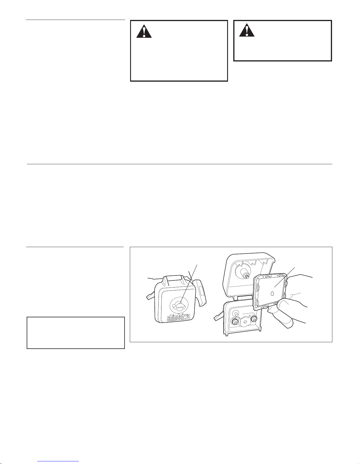
IMPORTANT!
The information contained in this own-
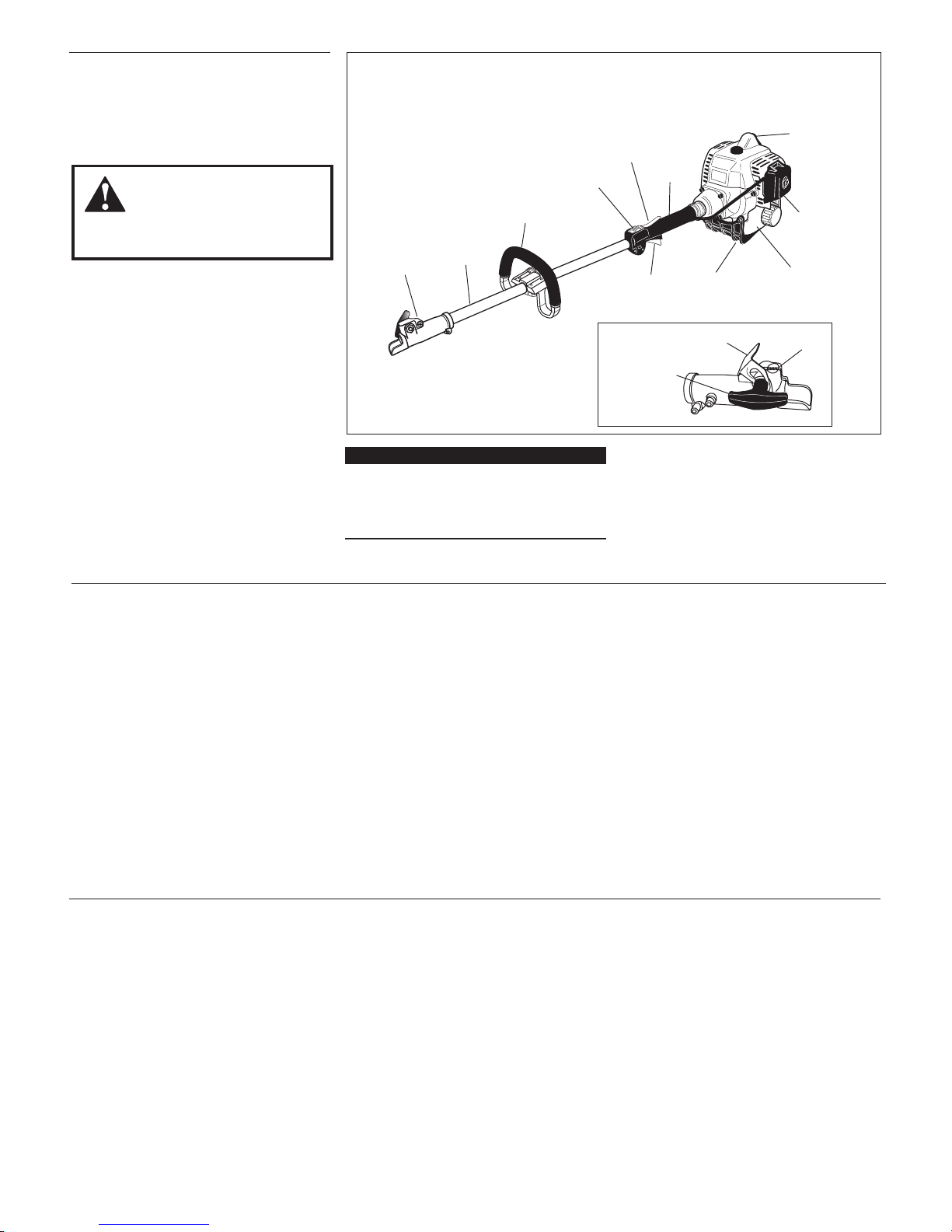
er's/operator's manual describes M230
Multipurpose Tool Carrier available at the
time of publication.
CAUTION!
A statement preceded by the word
“CAUTION” contains information
that should be acted upon to prevent
mechanical damage.
WARNING!
A statement preceded by the
triangular attention symbol and the
word “WARNING” contains informa-
tion that should be acted upon to
prevent serious bodily injury.
NOTE:
A statement preceded by the word “NOTE”
contains information that is handy to know
and may make your job easier.
IMPORTANT!
A statement preceded by the word
“IMPORTANT” is one that possesses
special significance.
Contents
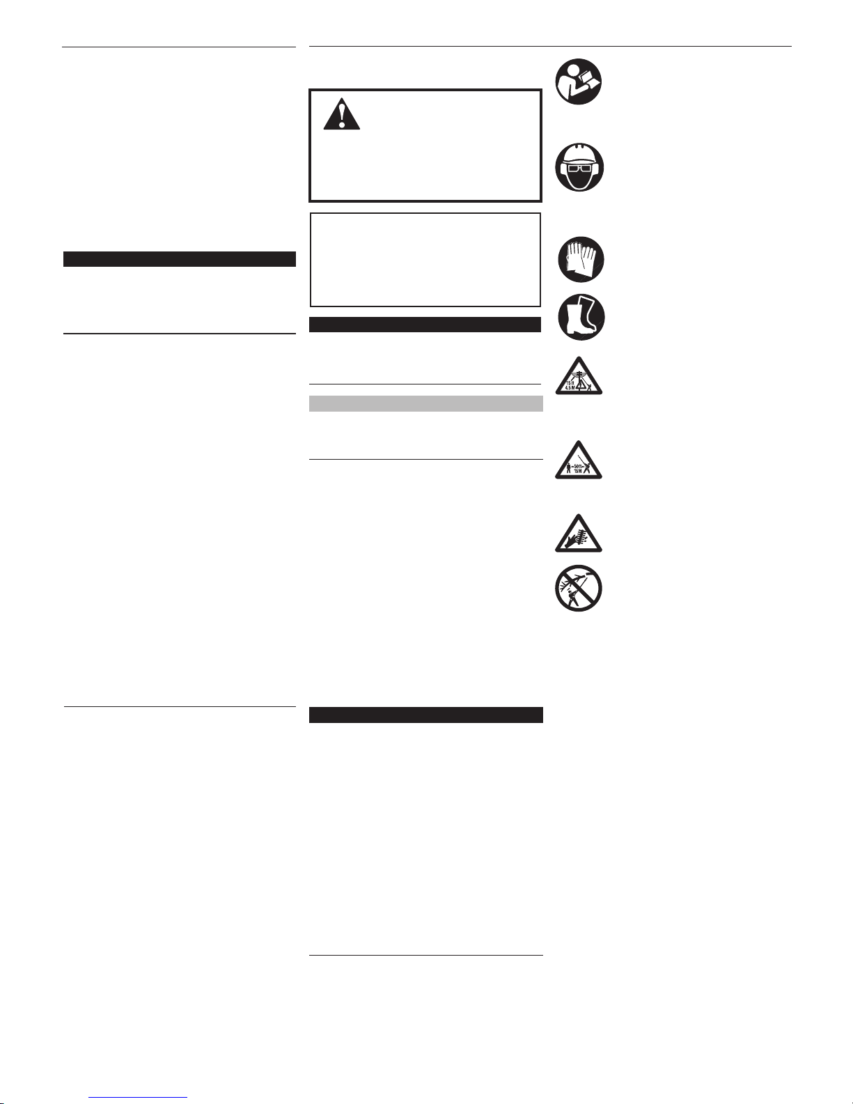
Be aware of the danger
of falling debris.
Shindaiwa Inc. reserves the right to make
changes to products without prior notice,
and without obligation to make alterations
to units previously manufactured.
Read and follow this manual, make
sure anyone using the trimmer
does likewise. Failure to do so
could result in serious personal
injury or machine failure. Keep
this manual for future reference.
Always wear a hard hat to reduce
the risk of head injuries during
operation of this machine. In addi-
tion, always wear eye and hearing
protection. Shindaiwa recom-
mends wearing a face shield as
additional face and eye protection.
Wear heavy duty, non-slip gloves.
Safety tip shoes or boots with
non-slip sole should be worn.
This product conducts electricity.
Keep the product and/or operator
a minimum distance of 15 feet
(4.5 meters) away from electri-
cal sources and power lines.
Keep bystanders at least 50
feet (15 meters) away from the
operating trimmer to reduce the
risk of being struck by falling
objects or thrown debris.
The blades / cutting attachments
are SHARP! Handle with care.
Introduction ...............................................2
Attention Statements.................................2
Safety Instructions ....................................3
Safety Labels..............................................3
Product Description..................................4
Specifications.............................................4
Assembly and Adjustments......................5
Adding/Removing a Tool Attachment....5
Mixing Fuel................................................6
Filling the Fuel Tank.................................6
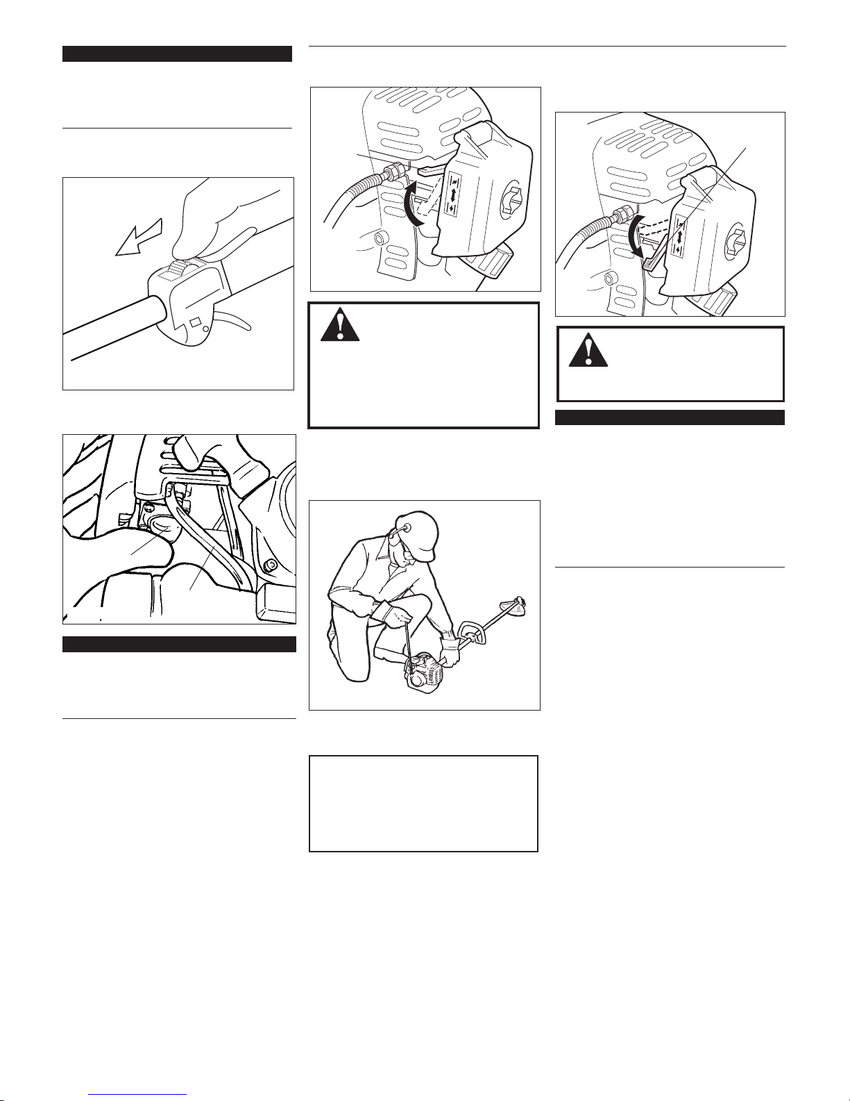
Starting the Engine ..................................7
Stopping the Engine..................................8
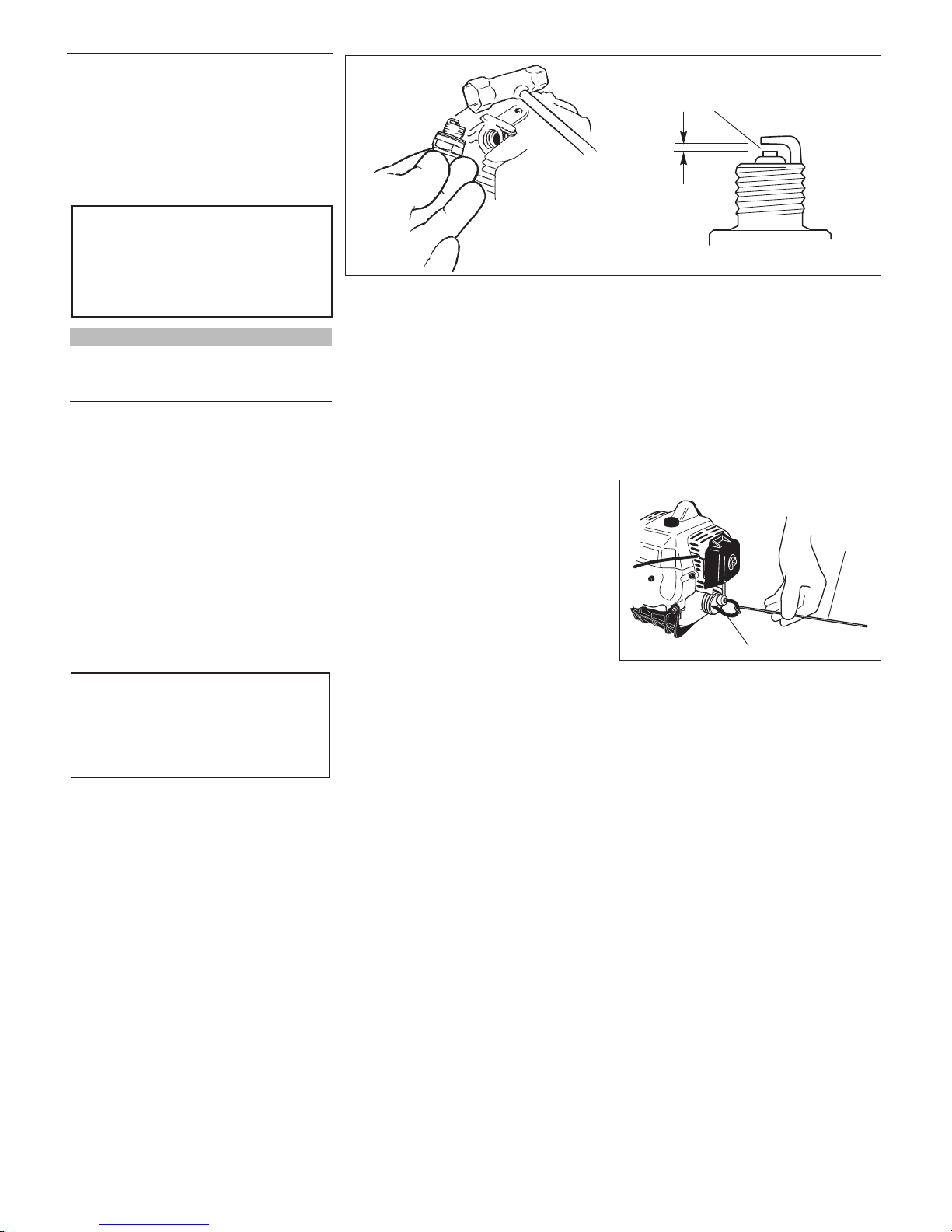
Adjusting Engine Idle ...............................8
Maintenance ..............................................9
Long Term Storage.................................11
Troubleshooting Guide ..........................12

3
ALWAYS wear eye protection to shield
against thrown objects.
ALWAYS wear hearing protection
devices when operating this unit.
NEVER operate the engine when
transporting the unit. Make sure cutter
safety guards are in place when trans-
porting this unit.
NEVER operate the engine indoors!
Make sure there is always good ventila-
tion. Fumes from engine exhaust can
cause serious injury or death.
ALWAYS make sure there are no missing
or loose fasteners and that the stop switch
and throttle controls are working properly.
ALWAYS use the proper cutting tool for
the job.
ALWAYS clear your work area of trash
or hidden debris that could be thrown
back at you or toward a bystander
ALWAYS make sure the cutting attach-
ment tool is properly installed and
rmly tightened before operation.
NEVER use a cracked or warped
cutting attachment: replace it with a
serviceable one and make sure it ts
properly.
ALWAYS stop the engine immediately
if it suddenly begins to vibrate or shake.
Inspect for broken, missing or improperly
installed parts or attachments.
ALWAYS keep the unit as clean as
practical. Keep it free of loose vegeta-
tion, mud, etc.
NEVER extend trimming line beyond
the length specied for your unit.
ALWAYS hold the unit rmly with both
hands when cutting or trimming, and
maintain control at all times.
ALWAYS keep the handles clean.
ALWAYS disconnect the spark plug wire
before performing any maintenance work.
BEFORE starting the engine make
sure the cutting attachment is not con-
tacting anything.
ALWAYS stop the engine immediately
and check for damage if you strike a
foreign object or if the unit becomes
tangled. Do not operate with broken or
damaged equipment.
Figure 1
M230
IMPORTANT!
Safety and Operation Information Labels:
Make sure all information labels are
undamaged and readable. Immediately
replace damaged or missing information
labels. New labels are available from your
local authorized Shindaiwa dealer.
Safety Labels
Attachments for the Multipurpose Tool
Carrier operate at very high speeds
and can do serious damage or injury if
they are misused or abused. Never allow
a person without training or instruction to
operate this unit!
Stay Alert
You must be physically and mentally fit to
operate this unit safely.
Safety Instructions
WARNING!
Never operate
power equipment of any
kind if you are tired or if you are under
the inuence of alcohol, drugs, medi-
cation or any other substance that
could affect your ability or judgement.
WARNING!
Never make unauthorized
attachment installations. Do not
use attachments not approved by
Shindaiwa for use on this unit.
WARNING!
Use Good Judgement
Work Safely

4
Product Description
Using the accompanying illustrations as
a guide, familiarize yourself with this unit
and its various components. See Figure 2.
Understanding your unit helps ensure top
performance, long service life and safer
operation.
Prior to Assembly
Before assembling, make sure you have all
the components required for a complete unit:
Engine/Outer tube assembly
Handle
Kit containing handle mounting bracket
and hardware, this owner/operator's
manual and tool kit for routine main-
tenance. Tool kits vary by model and
may include a hex wrench set, a spark
plug/screwdriver combination wrench,
and a spanner.
■
■
■
IMPORTANT!
The terms “left”, “left-hand”, and “LH”;
“right”, “right-hand”, and “RH”; “front”
and “rear” refer to directions as viewed by
the operator during normal operation.
Specications
WARNING!
Do not make unauthorized
modications or alterations to any of
these units or their components.
Engine Name ..................................................................................................................................................................................................M230
Engine model .................................................................................................................................................................................................. S230
Engine type................................................................................................................................................... 2-cycle, vertical cylinder, air cooled
Dry weight (less attachments)..........................................................................................................................................................4.2 kg/9.4 lb
Displacement ............................................................................................................................................................................. 22.5 cc/1.4 cu. in.
Bore x stroke............................................................................................................................................................... 32 x 28 mm/1.25 x 1.10 in.
Engine Speed at Maximum Power Output ..............................................................................................................................7,500 rpm (min-1)
Maximum power output..................................................................................................................................................................0.8 kW/1.1 hp
Engine speed at idling ...............................................................................................................................................................2,750 rpm (min-1)
Fuel tank capacity ...........................................................................................................................................................................554 cc/18.7 oz.
Fuel/oil ratio.......................................................................................................................................... 50:1 with Shindaiwa 2-cycle Mixing Oil
Carburetor ......................................................................................................................................................................................... Walbro WYL
Ignition ............................................................................................................................................. One piece electronic, transistor-controlled
Spark plug..........................................................................................................................................................................................NGK BMR6A
Air filter...................................................................................................................................................... Non-reversible flocked filter element
Starting method ............................................................................................................................................................................................ Recoil
Stopping method .................................................................................................................................................................................Slide switch
Transmission type .......................................................................................................................Automatic, centrifugal clutch with bevel gear
Figure 2
M23002a
Coupler Screw Knob
Latch
Latch protector
Figure 2a
M230
Coupler
Handle
Grip
Throttle Lockout
Lever
Ignition
Switch
Air
Cleaner
Spark
Plug
Fuel Tank
Throttle
Trigger Tank Guard
Outer
Tube
Specifications subject to change without notice.

5
Installing a Tool Attachment
Place the unit and tool assembly on a
clean, flat surface so that both assem-
blies fit end to end.
The unit should be facing up and the
tool assembly should be positioned with
the locking hole in the tube end facing
up. See Figure 4a.
1.
With the unit on a clean, flat surface,
loosen the coupler screw. The spring-
loaded coupler protector should pop up.
Press down on the latch with your
finger or thumb. This releases the
coupler lock. See Figure 5.
Pull the tool assembly out of the
coupler.
1.
2.
3.
CAUTION!
Keep the open ends of the tubes
clean and free of impurities!
Slip off the protective covers from the
ends of both tubes, and loosen the
coupler screw knob.
Insert the tool assembly into the cou-
pler, with the tool decal facing up, until
the line of the decal is flush with the end
of the coupler.
Twist the tool back and forth until you
are sure it snaps in place by the coupler
latch. See Figure 4a.
When the two tube halves are locked
together, press down on the spring-
loaded latch protector and tighten the
coupler screw. See Figure 4b.
2.
3.
4.
5.
Press
Latch
Figure 5
Removing a Tool Attachment
Latch Protector
(lowered)
Coupler Screw Knob
Coupler
Figure 4b
Figure 4a Tool Assembly
Tube Assembly
Coupler
Latch
Coupler Screw Knob
Locking Hole
Latch Protector (extended)
Connect the Handle to the Outer Tube.
Position the handle on the outer tube as
shown. See Figure 3.
Install the mounting bracket with the
socket-head screws. Tighten the screws
finger-tight ONLY at this time.
Locate the handle in the best position
for operator comfort (usually about 10
inches ahead of the throttle assembly).
Secure the handle by alternately
tightening the four socket-head screws
in a diagonal or “criss-cross” fashion.
1.
2.
3.
4.
Assembly and Adjustments
Outer Tube
Socket-head
Capscrews
Handle
Mounting Bracket
Throttle Assembly
Figure 3

6
Place the unit on a flat, level surface.
Clear any dirt or other debris from
around the fuel filler cap.
Remove the fuel cap, and fill the tank
with clean, fresh fuel.
Reinstall the fuel filler cap and tighten
firmly.
1.
2.
3.
4.
Filling the Fuel Tank
WARNING!
Minimize the risk of re!
STOP engine before refueling.
ALWAYS allow the engine to cool
before refueling!
Wipe all spilled fuel and move the
engine at least 10 feet (3 meters)
from the fueling point and source
before restarting!
NEVER start or operate this unit if
there is a fuel leak.
■
■
■
■
NEVER start or operate this unit if
the carburetor, fuel lines, fuel tank
and/or fuel tank cap are damaged.
NEVER smoke or light any res near
the engine or fuel source!
NEVER place any ammable mate-
rial near the engine mufer!
NEVER operate the engine without
the mufer and spark arrester in
good working condition.
■
■
■
■
Mixing Fuel
CAUTION!
This engine is designed to operate
on a 50:1 mixture consisting of
unleaded gasoline and ISO-L-EGD
or JASO FC class 2-cycle mixing oil
only. Use of non-approved mixing
oils can lead to excessive carbon
deposits.
CAUTION!
Some types of gasoline contain alco-
hol as an oxygenate. Oxygenated
gasoline may cause increased oper-
ating temperatures. Under certain
conditions, alcohol-based gasoline
may also reduce the lubricating
qualities of some 2-cycle mixing
oils. Never use any type of gasoline
containing more than 10% alcohol
by volume! Generic oils and some
outboard oils may not be intended
for use in high-performance engines,
and should never be used in your
Shindaiwa engine.
Use only fresh, clean unleaded gasoline
with a pump octane of 87 or higher.
Mix all fuel with a 2-cycle air-cooled
mixing oil that meets or exceeds ISO-
L-EGD and/or JASO FC classified oils
at 50:1 gasoline/oil ratio.
■
■
Examples of 50:1 mixing quantities
IMPORTANT!
Mix only enough fuel for your immediate
needs! If fuel must be stored longer than
30 days and oil with fuel stabilizer
is not used, it should first be treated with a
fuel stabilizer such as StaBil™.
Oil is a registered JASO FC
classified oil and also meets or exceeds
ISO-L-EGD performance requirements.
Shindaiwa One is recommended for use
in all Shindaiwa low emissions engines.
Shindaiwa One also includes a fuel
stabilizer.
Gasoline 2-cycle mixing oil
liters milliliters
2.5 - 1
50 ml
5 - 1 100 ml
10 - 1 200 ml
20 - 1 400 ml

7
23117
23121
23120
Primer Bulb
Return Tube
Open
Closed
ON
Starting the Engine
While holding the outer tube firmly
with left hand, use your other hand to
slowly pull the recoil starter handle
until resistance is felt.
4.
IMPORTANT!
Engine ignition is controlled by a two
position switch mounted on the throttle
housing labeled, “I” for ON or START
and “O” for OFF or STOP.
IMPORTANT!
The primer system only pushes fuel
through the carburetor. Repeatedly
pressing the primer bulb will not flood the
engine with fuel.
CAUTION!
Do not pull the recoil starter to the
end of the rope travel. Pulling the
recoil starter to the end of the rope
travel can damage the starter.
Set the choke lever to the CLOSED
position if engine is cold.
3.
Slide the ignition switch to the “I”
position.
1.
Press the primer bulb until fuel can be seen
flowing in the transparent return tube.
2.
WARNING!
Never start the engine from
the operating position.
When the Engine Starts...
After the engine starts, allow the
engine to warm up at idle 2 or 3 min-
utes before operating the unit.
After the engine is warm, pick up the
unit and clip on the shoulder strap if so
equipped. See the section on “Operat-
ing the Unit with a Shoulder Strap”.
Advancing the throttle makes the cut-
ting attachment turn faster; releasing
the throttle permits the attachment to
stop turning.
If the cutting attachment continues
to rotate when the engine returns to
idle, carburetor idle speed should be
adjusted. See the section “Adjusting
Engine Idle”.
■
■
■
■
IMPORTANT!
If the engine fails to start after several
attempts with the choke in the closed
position, the engine may be flooded
with fuel. If flooding is suspected, move
the choke lever to the open position
and repeatedly pull the recoil starter to
remove excess fuel and start the engine.
If the engine still fails to start, refer to the
troubleshooting section of this manual.
When the engine starts, slowly move
the choke lever to the “OPEN” position.
(If the engine stops after the initial
start, close the choke and restart.)
6.
WARNING!
The cutting attachment may
start to rotate when the engine is
started. Make sure the cutting
attachment is free of obstructions
before attempting to start the
engine!
When resistance is felt, pull quickly to
start the engine.
5.
Hold the outer
tube rmly with
left hand
Make sure the
cutting attachment is
free of obstructions
Figure 6
Figure 7
Figure 8
Figure 9
Figure 10

8
Idle the engine briefly before stopping
(about 2 minutes), then slide the ignition
switch to the “O” (Engine OFF) position.
Stopping the Engine
Adjusting Engine Idle Idle Speed Adjustment
Place the unit on the ground, then start
the engine, and then allow it to idle 2-3
minutes until warm.
If the attachment rotates when the
engine is at idle, reduce the idle speed
by turning the idle adjustment screw
counter-clockwise. See Figure 12.
If a tachometer is available, the engine idle
speed should be final adjusted to 2,750
(±250) min-1.
1.
2.
WARNING!
The cutting attachment must
NEVER rotate at engine idle! If the
idle speed cannot be adjusted by the
procedure described here, return the
trimmer to your Shindaiwa dealer for
inspection.
IMPORTANT
Carburetor fuel mixture adjustments are
preset at factory and cannot be serviced
in the field.
OFF
The engine must return to idle speed
whenever the throttle lever is released.
Idle speed is adjustable, and must be set
low enough to permit the engine clutch to
disengage the cutting attachment.
Figure 11
Figure 12

9
Prior to each work day, perform the
following:
Remove dirt or debris from the engine,
check the cooling fins and air cleaner
for clogging and clean them as neces-
sary.
■
General Maintenance
WARNING!
Non-standard parts may not
operate properly with your unit and
may cause damage and lead to
personal injury.
Mufer
This unit must never be operated with a
faulty or missing spark arrester or mufler.
Make sure the muffler is well secured and
in good condition. A worn or damaged
muffler is a fire hazard and may also
cause hearing loss.
Spark Plug
Keep the spark plug and wire connections
tight and clean.
Fasteners
Make sure nuts, bolts, and screws (except
carburetor adjusting screws) are tight.
Daily Maintenance
Check for loose or missing screws or
components. Make sure the cutting
attachment is securely fastened.
Check the entire unit for leaking fuel or
grease.
■
■
WARNING!
Before performing any main-
tenance, repair or cleaning work on
the unit, make sure the engine and
cutting attachment are completely
stopped. Disconnect the spark plug
wire before performing service or
maintnenance work.
10-Hour Maintenance
Figure 13
Loosen Knob Remove and clean or
replace the element
CAUTION!
Never operate the unit if the air
cleaner assembly is damaged or
missing!
Every 10 hours of operation (more fre-
quently in dusty or dirty conditions):
Remove the air cleaner element. See
figure 14. Clean or replace as neces-
sary.
To clean element:
Wash the air filter element thoroughly
in soap and water. Let it dry before
reinstalling the element.
■
Carefully remove any accumulation of
dirt or debris from the muffler or the
fuel tank. Dirt build-up in these areas
could cause engine overheating, induce
premature wear, or create a fire hazard.
■

10
M23016
50-hour Maintenance
Remove and replace the fuel filter
element.
Use a hooked wire to extract the fuel
filter from inside the fuel tank. See
Figure 15.
Before reinstalling the new filter element,
inspect the condition of all the fuel system
components (fuel pick-up line, fuel return
line, tank vent line, tank vent, fuel cap and
fuel tank).
■
CAUTION!
Make sure you do not pierce the fuel
line with the end of the hooked wire.
The line is delicate and can be dam-
aged easily.
Every 10 to 15 hours of operation:
Remove and clean the spark plug.
Adjust the spark plug electrode gap to
0.024 in./0.6 - 0.7 mm.
If the spark plug must be replaced,
use only an NGK
BMR6A
or equivalent
resistor type spark plug of the correct
heat range. See Figure 14.
■
CAUTION!
Before removing the spark plug,
clean the area around the plug to
prevent dirt and debris from getting
into the engine’s internal parts.
10/15-Hour Maintenance
If damage, splitting or deterioration
is noted, the unit should be removed
from service until it can be inspected or
repaired by a Shindaiwa-trained service
technician.
NOTE:
The NGK BMR6A also meets the require-
ments for electro magnetic compliance
(EMC).
Clean the spark plug
and check the gap at
the electrode.
0.024 in.
(0.6 mm)
Hooked
Wire
Filter Element
Figure 14
Figure 15

11
Long Term Storage
Before storing the unit, repair or
replace any worn or damaged parts.
Remove the air cleaner element from
the carburetor and clean it thoroughly
with soap and water. Let dry and reas-
semble the element.
Store the unit in a clean, dust-free area.
■
■
■
Whenever the unit will not be used for 30
days or longer, use the following proce-
dures to prepare it for storage:
Clean external parts thoroughly and apply
a light coating of oil to all metal surfaces.
Drain all the fuel from the fuel tank.
■
■
Remove the remaining fuel from the
fuel lines and carburetor:
Prime the primer bulb until no more
fuel is passing through.
Start and run the engine until stops
running.
Repeat steps 1 and 2 until the engine
will no longer start.
Remove the spark plug and pour
about 1/4 ounce of 2-cycle mixing oil
into the cylinder through the spark
plug hole. Slowly pull the recoil
starter 2 or 3 times so oil will evenly
coat the interior of the engine.
Reinstall the spark plug.
■
1.
2.
3.
4.
5.
CAUTION!
Gasoline stored in the carburetor for
extended periods can cause hard start-
ing and could also lead to increased
service and maintenance cost.
Inspect and clean the spark arrestor
screen.
WARNING!
Never operate the unit with a
damage or missing mufer or spark
arrester! Operating with a missing or
damaged spark arrester is a re hazard
and could also damage your hearing.
IMPORTANT!
If you note excessive carbon buildup,
consult with an authorized Shindaiwa
servicing dealer.
Remove the spark plug boot.
Remove the engine cover by loosening
the engine cover knob ) and lifting the
cover from the engine.
Remove the spark arrester screen
screw.
Remove the spark arrester screen and
clean with a stiff bristle brush.
Reassemble the spark arrester screen
and engine cover in reverse order.
1.
2.
3.
4.
5.
IMPORTANT!
All stored fuels should be stabilized with a
fuel stabilizer such as STA-BIL™
, if
oil with fuel stabilizer is not used.
Mufer Maintenance
Engine Cover Engine Cover Knob
Figure 16
Spark Arrestor Screen
Spark Arrestor
Retaining Screw
Mufer

12
NO
NO
YES
NO
YES
NO
YES
YES
NO
YES
Does the engine
crank?
Does the tank contain
fresh fuel of the proper
grade?
Is fuel visible and
moving in the return
line when priming?
Is there spark at
the spark plug wire
terminal?
Check the spark plug.
The plug is damaged internally or of
the wrong size.
What To Check Possible Cause Remedy
ENGINE DOES NOT START
Faulty recoil starter.
Fluid in the crankcase.
Internal damage.
Loose spark plug.
Excess wear on cylinder, piston,
rings.
Fuel incorrect, stale, or
contaminated; mixture incorrect.
Check for clogged fuel filter and/
or vent.
The ignition switch is in “O” (OFF)
position.
Shorted ignition ground.
Faulty ignition unit.
If the plug is wet, excess fuel may be
in the cylinder.
The plug is fouled or improperly
gapped.
Consult with an authorized
servicing dealer.
Tighten and re-test.
Consult with an authorized
servicing dealer.
Refill with fresh, clean unleaded gasoline
with a pump octane of 87 or higher mixed
with 50:1 Shindaiwa Premium 2-cycle
mixing oil or with an equivalent high quality
2-cycle mixing oil.
Replace fuel filter or vent as required.
Restart.
Move switch to “I” (ON) position and
restart.
Consult with an authorized servicing
dealer.
Crank the engine with the plug removed,
reinstall the plug, and restart.
Clean and regap the plug to 0.024 in./
0.6mm-0.7mm. Restart.
Replace the spark plug. Check the unit
Specifications page for the proper spark
plug for your unit. Restart.
Good compression?
Troubleshooting Guide

13
Operator is overworking the unit.
Carburetor mixture is too lean.
Improper fuel ratio.
Fan, fan cover, cylinder fins dirty or
damaged
Carbon deposits on the piston or in the
muffler.
Clogged air cleaner element.
Loose or damaged spark plug.
Air leakage or clogged fuel line.
Cut at slower rate.
Consult with an authorized servicing
dealer.
Refill with clean fresh unleaded gasoline
with a pump octane of 87 or higher, mixed
with Premium 2-cycle mixing oil at a 50:1
gasoline/oil ratio.
Clean, repair or replace as necessary.
Consult with an authorized servicing
dealer
Clean or replace the air filter
Tighten or replace the spark plug.
Restart. Check the "Specifications" page
in this manual for the correct spark plug
for this unit.
Repair or replace fuel filter and/or
fuel line.
Water in the fuel.
Piston seizure.
Faulty carburetor and/or diaphragm
Overheating condition.
Improper fuel.
Carbon deposits in the combustion
chamber.
Check fuel octane rating; check for
presence of alcohol in the fuel. Refuel
as necessary.
Consult with an authorized servicing
dealer.
Refill with fresh fuel/oil mixture.
Consult with an authorized servicing
dealer.
Consult with an authorized servicing
dealer.
Is the engine overheating?
Engine is rough at all
speeds. May also have black
smoke and/or unburned
fuel at the exhaust.
Engine is knocking.
LOW POWER
What To Check Possible Cause Remedy
Troubleshooting Guide (continued)

14
ADDITIONAL PROBLEMS
Fuel tank empty.
Clogged fuel filter.
Water in the fuel.
Shorted spark plug or loose terminal.
Ignition failure.
Piston seizure.
Ground (stop) wire is disconnected or
switch is defective
Overheating due to incorrect spark
plug
Clogged air filter.
Clogged fuel filter.
Lean fuel/air mixture.
Idle speed set too low.
Switch turned off.
Refuel. See See "Filling the Fuel Tank"
section of manual.
Replace fuel filter.
Drain; replace with clean fuel. See "Filling
the Fuel Tank" section of manual.
Clean or replace spark plug. Check the
"Specifications" page in this manual for the
proper spark plug for your unit. Tighten the
terminal.
Replace the ignition unit.
Consult with an authorized servicing
dealer
Test and replace as required.
Replace the spark plug. Check the
Specifications page in this manual for
the proper spark plug for your unit.
Clean or replace the air filter.
Replace the fuel filter.
Consult with an authorized servicing
dealer.
Adjust: 2,750 (±250) min-1.
Reset the switch and re-start.
Overheated engine.
Engine idle too high.
Broken clutch spring or worn clutch
spring boss.
Loose attachment holder.
Warped or damaged attachment.
Loose gearcase.
Poor acceleration.
Engine stops abruptly.
Engine difficult to shut
off.
Cutting attachment moves
at engine idle.
Excessive vibration.
Attachment will not rotate.
Idle engine until cool.
Set idle: 2,750 (±250) min-1.
Replace spring/shoes as required,
check idle speed.
Inspect and re-tighten holders securely.
Inspect and replace attachment as
required.
Tighten gearcase securely.
Bent main shaft/worn or damaged
bushings.
Shaft not installed in powerhead or
gearcase.
Broken shaft.
Damaged gearcase.
Inspect and replace as necessary.
Inspect and reinstall as required.
Consult with a authorized servicing
dealer.
What To Check Possible Cause Remedy
Troubleshooting Guide (continued)

15
NOTES

NOTES
Shindaiwa Inc.
11975 S.W. Herman Road
Tualatin, Oregon 97062
Telephone: 503 692-3070
Fax: 503 692-6696
www.shindaiwa.com
Shindaiwa Corporation
Head Office:
6-2-11, Ozuka-Nishi
Asaminami-Ku, Hiroshima
731-3167, Japan
Telephone: 81-82-849-2220
Fax: 81-82-849-2481
©2007 Shindaiwa, Inc.
Part Number 65028-94310
Revision 7/07
Shindaiwa is a registered trademark of Shindaiwa, Inc.
Specifications subject to change without notice.
16

Manual Del ProPietario / oPeraDor ShinDaiwa
M230 Porta
herraMienta MultiPle
M230
Part Number 65028-94310 Rev. 2/07
Reduzca al mínimo el riesgo de lesiones, tanto a usted mismo como a otras personas.
Lea detenidamente este manual y familiarícese con su contenido.
Protéjase los ojos y los oídos siempre que trabaje con esta unidad.
Esta máquina está diseñada para cortar setos.
No utilice esta máquina ni efectúe trabajos de mantenimiento en ella sin haber
comprendido claramente todas las explicaciones de este manual.
Mantenga el manual a su alcance en todo momento, de modo que pueda con-
sultarlo si le surge alguna duda sobre el manejo de la máquina.
■
■
■
■
■
■
¡aDVertenCia!

2
A travéz de este manual se encuentran
“declaraciones de seguridad” especiales..
¡IMPORTANTE!
El propósito de los procedimientos
operacionales descritos en este manual
es ayudarle a obtener el más alto ren-
dimiento de su máquina y proteger
a usted y a otras personas de sufrir
lesiones. Estos procedimientos son pautas
operativas para una operación segura bajo
la mayoría de condiciones y no tienen el
propósito de substituir las normas y/o
leyes vigentes en su área. Si tiene alguna
pregunta relacionada con su Serie 2510
o si no entiende alguna información
contenida en este manual, consulte a su
distribuidor Shindaiwa, quien le atenderá
con gusto. También puede comunicarse
con Shindaiwa Inc. a la dirección que apa-
rece en la contra portada de este manual.
Declaraciones De SeguridadIntroducción
PAGE
La Serie 230 de maquinaria manual
Shindaiwa, ha sido disenada y construida
para suministrar un rendimiento superior
sin comprometer calidad, comodidad
ni durabilidad. Los motores Shindaiwa
representan la technologia lider de motores
de alto rendimiento, con excepcional alta
potencia de peso y cilindrada sumamente
bajos. Como proprietario/operario, usted no
tardara en comprobar que Shindaiwa es la
unica maquina en esta clase!
¡IMPORTANTE!
La información contenida en este manual
del proprietario/operario describe la
Porta Herramienta Multiple M230
disponibles a la fecha de su publicación.
¡PRECAUCIÓN!
Toda información precedida por la
palabra PRECAUCION! contiene
información que se debe cumplir
para evitar daños mecánicos.
¡ADVERTENCIA!
Toda información precedida
por un símbolo triangular de advert-
encia y la palabraADVERTENCIA!
contiene información o procedimien-
tos que se deben cumplir para evitar
lesiones.
NOTA:
Toda información precedida por la
palabra “NOTA” contiene información útil
que puede hacer su trabajo más fácil.
¡IMPORTANTE!
Toda información precedida por la palabra
“IMPORTANTE” contiene información
especial y significante.
Índice
Tenga cuidado con el escombro que
cae de los árboles o de la maleza.
Shindaiwa Inc. se reserva el derecho
de realizar cambios a sus productos sin
previo aviso, y sin la obligación de hacer
modificaciones a máquinas fabricadas
previamente.
Lea y siga el manual, asegurese de
que quien use esta podadora también
lo lea. En caso de no leerlo y usar
la podadora apropiadamente puede
causarle serias lesiones tanto a
usted como a la maquina. Guarde el
manual para futuras consultas.
Siempre utilice un casco para reducir
el riesgo de lesiones en la cabeza
al momento de utilizar la maquina.
También utilice siempre lentes de
protección así como protector para
los oídos. Shindaiwa recomienda que
utilicen un protector para la cara como
medida de protección adicional.
Utilice guantes para trabajo que
sean antiresbalantes.
Botas de seguridad o botas de
trabajo antirederrapantes también
deben de se usadas.
Estos productos atraen electricidad.
Debe mantenerse la maquina así
como el operador a una distancia
de 4,5 metros de distancia de toda
fuente de electricidad.
La gente debe de permanecer a 15
metros de la maquina cuando esta
en operación, esto para reducir el
riesgo de ser golpeado por objetos
que están siendo cortados.
Las cuchillas o utensilios para cor-
tar son muy “FILOSOS” Manéjelos
con cuidado.
Declaraciones De Seguridad ...................2
Instrucciones Generales de Seguridad...3
Etiquetas de Seguridad.............................3
Descripción del Producto.........................4
Especificaciones........................................4
Ensamblaje y Ajustes................................5
Mezcla de Combustible............................6
Llenando el Tanque de Combustible ......6
Arranque del motor ..................................7
Parada del motor.......................................8
Ajuste de Marcha Mínima del Motor......8
Mantenimiento .........................................9
Almacenamiento de Largo Plazo...........11
Guia Diagnostico.....................................12

3
SIEMPRE use protección para los
ojos como escudo contra objetos
lanzados.
SIEMPRE use proteccion auditiva
cuando opere esta unidad.
NUNCA opere el motor cuando trans-
porte la unidad. Cerciorese de que
los protectores de corte esten en su
lugar cuando transporte la unidad.
NUNCA opere la unidad en el inte-
rior! Cerciorese que siempre haya
buena ventilación. El humo o gases
del escape del motor pueden causar
serias lesiones o la muerte.
SIEMPRE verica que no haya
sujetadores que falta o ojos y que el
interruptor y acelerador están funcio-
nando correctamente.
SIEMPRE use el accesorio de corte
apropiado.
SIEMPRE mantenga su area de
trabajo libre de basura u objetos que
pueden rebotar contra usted o contra
transeúntes.
SIEMPRE cerciore que el accesorio
de corte este propiamente instalado y
rmemente apretado antes de empe-
zar a operar.
NUNCA use un accesorio de corte
quebrado o doblado. Reemplacelo
por uno util y cerciore de que este
propriamente situado.
SIEMPRE pare el motor inmediata-
mente y revise en busca de daños si
golpea un objeto extraño o si la uni-
dad se enreda. No opere con equipo
dañado o quebrado.
SIEMPRE mantenga la máquina lo
más limpia posible. Mantengala libre de
vegetación, barro, etc.
NUNCA extienda el cable de nylon más
allá de lo especicado para su máquina.
SIEMPRE sujete la máquina rme-
mente con ambas manos cuando
corte o recorte, y mantenga el control
en todo momento.
SIEMPRE mantenga los mangos
limpios.
SIEMPRE desconente el cable de
bujía antes de hacer mantenimiento
a la máquina.
ANTES de encender el motor, cer-
ciore de que el accesorio de corte no
este en contacto con algo.
SIEMPRE detenga el motor inmedi-
atament y revise en busca de danos,
si golpea un objeto extrano o si la
unidad se enreda. NO opere con
equipo quebrado o danado.
Figura 1
M230
¡IMPORTANTE!
Etiquetas de Seguridad y de Información
de Operación: Asegurese que toda las
etiquetas estén libres de daños y legibles.
Reemplace inmediatamente etiquetas
dañadas o faltantes. Etiquetas nuevas están
disponibles en su centro de servicio local
autorizado de Shindaiwa.
Etiquetas de Seguridad
Los accesorios para la porta herramienta
multiple operan a velocidades altas y
pueden causar daños o lesiones serias si son
malusadas o abusadas. Nunca permita que
una persona sin entrenamiento o instrucción
opere esta unidad !
Mantengase Alerta
Debe de estar físicamente y mentalmente
en forma para operar esta máquina con
seguridad.
Instrucciones Generales de Seguridad
¡ADVERTENCIA!
Nunca opere
ninguna máquinaria motori-
zada si está cansado o si está bajo la
inuencia de alcohol, drogas o medica-
mentos o cualquier otra substancia que
pueda afectar su abilidad y juicio.
¡ADVERTENCIA!
Nunca instale accesorios no
autorizados. No use accesorios no
aprobados por Shindaiwa en esta
unidad.
ADVERTENCIA!
Use Buen Juicio
Trabaje con cuidado

4
Descripción del Producto
Use las ilustraciones como guía, famil-
iarícese con esta unidad y sus varios
componentes. Consulte la figura 2.
Conociendo la unidad le ayudará a obtener
alto rendimiento, vida útil más prolongada
y operación con seguridad
Antes de Ensamblar
Antes de ensamblar, cerciórese de que
tenga todos los componentes necesarios
para armar una máquina completa.
Ensamblaje del motor y tubo exterior.
Mango
Caja conteniendo la abrazadera y piezas
para montar el mango, este manual del
propietario/operador y juego de herra-
mientas para mantenimiento rutinario.
Las cajas de herramientas varian por
modelo y pueden incluir una llave hex-
agonal, llave bujía y destonillador, y una
llave inglesa.
■
■
■
¡IMPORTANTE!
Los términos “izquierda”, “mano izqui-
erda”, y “LH”; “derecha”, “mano derecha”,
y “RH”, “delantera” y “trasera”, indican
direcciones desde el punto de vista del
operador durante la operación normal de
este producto.
Especicaciones
¡ADVERTENCIA!
No haga modicaciones
o alteraciones no autorizadas a
ninguna de éstas máquinas ni a sus
componentes.
Nombre del modelo........................................................................................................................................................................................M230
Modello de motor............................................................................................................................................................................................ S230
Tipo de motor..........................................................................................................................2 tiempos, cilindro vertical, refrigerado por aire
Peso seco (sin accesorios para cortar).............................................................................................................................................4,2 kg/9,4 lb
Cilindrada .................................................................................................................................................................................... 22,5 cc/1,4 cu. in
Diámetro x Carrera..................................................................................................................................................... 32 x 28 mm/1,25 x 1,10 in.
Régimen de giro a la potencia máxima ....................................................................................................................................7.500 rpm(min-1)
Potencia Máxima..............................................................................................................................................................................0.8 kW/1,1 hp
Régimen de giro al ralentí ........................................................................................................................................................2.750 rpm (min-1)
Capacidad del Tanque de Combustible........................................................................................................................................554 cc/18,7 oz.
Proporción combustible/aceite....................................................................................................................................................................... 50:1
Tipo de Carburador .......................................................................................................................................................................... Walbro WYL
Sistema de Encendido ............................................................................................................................Electrónico, controlado por transistor
Bujía....................................................................................................................................................................................................NGK BMR6A
Filtro de Aire........................................................................................................................................................... Filtro de fieltro no reversible
Metodo de Arranque ................................................................................................................................................... Arrancador autorretráctil
Metodo de Parada .....................................................................................................................................................................Arrancador suave
Tipo de Transmisión.......................................................................................Automática, embrague centrífugo con engranajes helicoidales
Especificaciones conforme a cambio sin el aviso
Figura 2
M23002a
Figura 2a
M230
Tubo exterior
Agarrador
Mango
Gatillo del
acelerador
Seguro del
acelerador
Interruptor de
encendido
Tanque de
combustible
Perilla de tornillo
del acoplador
Seguro
Protector de seguro
Acoplador
Bujía
Filtro de aire
Tanque
protector
Other manuals for M230 EMC
2
Table of contents
Languages:
Other Shindaiwa Power Tools manuals
Popular Power Tools manuals by other brands

Craftsman
Craftsman 315.25791 Operator's manual

Milwaukee
Milwaukee M12 2460-20 Operator's manual

Orbitalum
Orbitalum RA 41 Plus operating instructions

EINHELL
EINHELL TE-MG 12 Li Original operating instructions

Bosch
Bosch GOP 18 V-EC professional Original instructions

Epiroc
Epiroc SB Series Safety and operating instructions