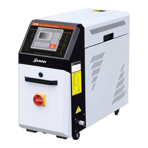
Shini STM-EB User manual

STM-EB
"Budget" Heater
Date:Apr, 2017
Version: Ver.A(English)


3(76)
Contents
1. General Description.....................................................................................9
1.1 CodingPrinciple....................................................................................10
1.2 Feature..................................................................................................10
1.3 Option...................................................................................................10
1.4 TechnicalSpecifications........................................................................12
1.4.1 Specification...............................................................................12
1.4.2 PumpPerformance.....................................................................13
1.4.3 ReferenceFormulaofMouldControllersModelSelection..........13
1.5 SafetyRegulations................................................................................14
1.5.1 SafetySignsand Labels.............................................................14
1.5.2 Signsand Labels........................................................................15
1.5.3 OperationRegulations................................................................15
1.6 ExemptionClause.................................................................................16
2. StructureCharacteristics and WorkingPrinciple....................................17
2.1 WorkingPrinciple..................................................................................17
2.1.1 SystemFlowforSTM-607-EB(IndirectCooling)........................17
2.1.2 SystemFlowforSTM-607W-EB (Direct Cooling).......................18
2.2 AssemblyDrawing................................................................................19
2.2.1 SystemStructureDrawing(STM-607-EB)..................................19
2.2.2 PartsList (STM-607-EB).............................................................20
2.2.3 HeatingTankAssembly(STM-607-EB)......................................21
2.2.4 HeatingTankPartsList (STM-607-EB)......................................22
2.2.5 CoolingWaterInlet ConnectingAssembly(STM-607-EB)..........23
2.2.6 PartsList (STM-607-EB).............................................................23
2.2.7 CooingWaterOutlet ConnectingAssembly(STM-607-EB)........23
2.2.8 PartsList (STM-607-EB).............................................................23
2.2.9 SystemStructureDrawing(STM-607W-EB)...............................24
2.2.10PartsList (STM-607W-EB).........................................................25
2.2.11SystemStructureDrawing(STM-910-EB)..................................26
2.2.12PartsList (STM-910-EB).............................................................27
2.2.13HeatingTankStructure(STM-910-EB).......................................28

4(76)
2.2.14HeatingTankPartsList (STM-910-EB)......................................29
2.2.15HeatingTankAssemblyDrawing(STM-910-EB)........................30
2.2.16HeatingTankPartsList (STM-910-EB)......................................31
2.2.17SystemStructureDrawing(STM-910W-EB)...............................32
2.2.18PartsList (STM-910W-EB).........................................................33
2.2.19HeatingTankDrawing(STM-910W-EB).....................................34
2.2.20PartsListofHeatingTank(STM-910W-EB)...............................35
2.3 ElectricalDiagram.................................................................................36
2.3.1 MainCircuit Dia. (STM-607-EB 400V)........................................36
2.3.2 ControlCircuit Dia. (STM-607-EB 400V)....................................37
2.3.3 ElectricalComponentsLayout (STM-607-EB 400V)...................38
2.3.4 ElectricalComponentsList (STM-607-EB 400V)........................39
2.3.5 MainCircuit Dia. (STM-607W-EB 400V).....................................40
2.3.6 ControlCircuit Dia. (STM-607W-EB400V).................................41
2.3.7 ElectricalComponentsLayout (STM-607W-EB 400V)...............42
2.3.8 ElectricalComponentsList (STM-607W-EB 400V).....................43
2.3.9 MainCircuit Dia. (STM-910-EB 400V)........................................44
2.3.10ControlCircuit Dia. (STM-910-EB 400V)....................................45
2.3.11ElectricalComponentsLayout (STM-910-EB 400V)...................46
2.3.12ElectricalComponentsList (STM-910-EB 400V)........................47
2.3.13MainCircuit Dia. (STM-910W-EB 400V).....................................48
2.3.14ControlCircuit Dia. (STM-910W-EB400V).................................49
2.3.15ElectricalComponentsLayout (STM-910W-EB 400V)...............50
2.3.16ElectricalComponentsList (STM-910W-EB 400V).....................51
2.3.17MainCircuit Dia. (STM-607-EB 230V)........................................52
2.3.18ControlCircuit Dia. (STM-607-EB 230V)....................................53
2.3.19ElectricalComponentsLayout (STM-607-EB 230V)...................54
2.3.20ElectricalComponentsList (STM-607-EB 230V)........................55
2.3.21MainCircuit Dia. (STM-607W-EB 230V).....................................56
2.3.22ControlCircuit Dia. (STM-607W-EB230V).................................57
2.3.23ElectricalComponentsLayout (STM-607W-EB 230V)...............58
2.3.24ElectricalComponentsList (STM-607W-EB 230V).....................59
3. Installation and Debugging........................................................................60
3.1 Installation Space..................................................................................60

5(76)
3.2 PowerSupply........................................................................................60
3.3 OperationProcedures...........................................................................61
3.3.1 Installation StepsforOptionsWaterManifold(Dewaxing)..........61
3.3.2 Installation StepsforOptionsWaterManifold(Welding).............62
3.4 Mouldand WaterCoupling....................................................................62
3.4.1 Add HeatTransferOil.................................................................64
4. Operation Guide.........................................................................................65
4.1 ControlPanel........................................................................................65
4.2 Machine Startup....................................................................................66
4.3 Machine Shutdown................................................................................66
4.4 TemperatureController.........................................................................67
4.4.1 SettingConfirmation...................................................................68
5. Trouble-shooting........................................................................................69
6. Maintenance and Repair............................................................................71
6.1 OpentheCovers...................................................................................72
6.2 YType Strainer.....................................................................................72
6.3 SolenoidValve......................................................................................73
6.4 Pipe Heater...........................................................................................73
6.5 CoolingPipe..........................................................................................73
6.6 HeatTransferOil...................................................................................74
6.6.1 HeatTranferOil Replacement....................................................74
6.7 MaintenanceSchedule..........................................................................75
6.7.1 About theMachine......................................................................75
6.7.2 Installation &Inspection..............................................................75
6.7.3 DailyChecking............................................................................75
6.7.4 WeeklyChecking........................................................................75
6.7.5 TrimonthlyChecking...................................................................75
6.7.6 Half-yearlyChecking...................................................................75
6.7.7 YearlyChecking..........................................................................76
6.7.8 3yearChecking..........................................................................76
TableIndex

6(76)
Table2-1: PartsList (STM-607-EB)..................................................................20
Table2-2: HeatingTankPartsList(STM-607-EB)...........................................22
Table2-5: PartsList (STM-607W-EB)..............................................................25
Table2-6: PartsList (STM-910-EB)..................................................................27
Table2-11:ElectricalComponentsList (STM-607-EB 400V)...........................39
Table2-12:ElectricalComponentsList (STM-607W-EB 400V).......................43
Table2-13:ElectricalComponentsList (STM-910-EB 400V)...........................47
Table2-14:ElectricalComponentsList (STM-910W-EB 400V).......................51
Table2-15:ElectricalComponentsList (STM-607-EB 230V)...........................55
Table2-16:ElectricalComponentsList (STM-607W-EB 230V).......................59
Table3-1: MainPipe Simension.......................................................................61
PictureIndex
Picture1-1: PumpPerformance.......................................................................13
Picture2-1: STM-607-EB WorkingPrinciple.....................................................17
Picture2-2: STM-607W-EBWorkingPrinciple.................................................18
Picture2-3: SystemStructureDrawing(STM-607-EB).....................................19
Picture2-4: HeatingTankAssembly(STM-607-EB).........................................21
Picture2-5: CoolingWaterInlet ConnectingAssembly(STM-607-EB)............23
Picture2-6: CoolingWaterOutlet ConnectingAssembly(STM-607-EB)..........23
Picture2-7: SystemStructureDrawing(STM-607W-EB).................................24
Picture2-8: SystemStructureDrawing(STM-910-EB)......................................26
Picture2-9: HeatingTankStructure(STM-910-EB).........................................28
Picture2-10: HeatingTankAssembly(STM-910-EB).......................................30
Picture2-11:SystemStructureDrawing(STM-910W-EB)...............................32
Picture2-12: HeatingTankDrawing(STM-910W-EB)......................................34
Picture2-13: MainCircuit Dia. (STM-607-EB400V).........................................36
Picture2-14: ControlCircuit Dia. (STM-607-EB 400V).....................................37
Picture2-15:ElectricalComponentsLayout (STM-607-EB 400V)...................38
Picture2-16: MainCircuit Dia. (STM-607W-EB 400V).....................................40
Picture2-17: ControlCircuit Dia. (STM-607W-EB 400V)..................................41
Picture2-18:ElectricalComponentsLayout (STM-607W-EB 400V)................42
Picture2-19: MainCircuit Dia. (STM-910-EB400V).........................................44

7(76)
Picture2-20: ControlCircuit Dia. (STM-910-EB 400V).....................................45
Picture2-21:ElectricalComponentsLayout (STM-910-EB 400V)...................46
Picture2-22: MainCircuit Dia. (STM-910W-EB 400V).....................................48
Picture2-23: ControlCircuit Dia. (STM-910W-EB 400V)..................................49
Picture2-24:ElectricalComponentsLayout (STM-910W-EB 400V)................50
Picture2-25: MainCircuit Dia. (STM-607-EB230V).........................................52
Picture2-26: ControlCircuit Dia. (STM-607-EB 230V).....................................53
Picture2-27:ElectricalComponentsLayout (STM-607-EB 230V)...................54
Picture2-28: MainCircuit Dia. (STM-607W-EB 230V).....................................56
Picture2-29: ControlCircuit Dia. (STM-607W-EB 230V)..................................57
Picture2-30:ElectricalComponentsLayout (STM-607W-EB 230V)................58
Picture3-1: Installation Space..........................................................................60
Picture3-2: Mouldand WaterCoupling1.........................................................62
Picture3-3: Mouldand WaterCoupling2.........................................................63
Picture3-4: Mouldand WaterCoupling3.........................................................63
Picture3-5: HeatTransferOil Filling1..............................................................64
Picture3-6: HeatTransferOil Filling2..............................................................64
Picture3-7: HeatTransferOil Filling3..............................................................64
Picture4-1: ControlPanel.................................................................................65
Pictuer4-2: MachineStartup............................................................................66
Picture4-3: ControlPanel.................................................................................67
Picture6-1: Open theMachine.........................................................................72
Picture6-2: YType Strainer.............................................................................72
Picture6-3: SolenoidValve..............................................................................73
Picture6-4: PipeHeater...................................................................................73
Picture6-5: CoolingPipe..................................................................................73
Picture6-6: Oil Inlet..........................................................................................74

8(76)

9(76)
1. General Description
Read thismanualcarefullybeforeoperationtopreventdamageofthe
machine orpersonalinjuries.
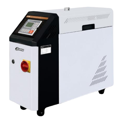
STM-EB (W-EB)seriesareapplicableforheatingup themouldsandmaintaining
temperature,andtheyalsocanbeusedinothersimilarapplications. Firstly, these
seriesadoptdifferent coolingmethodstocooldownmediums, thenmediumsare
conveyed tothe mouldsafterpressurized bypumpand heatedupbyelectrical
heated tube. Optimizeddesignensuresaccurateheatingtemperature, the
max.temperaturecan reach:wateris120and oil is200.
Model: STM-607W-EB

10(76)
1.1CodingPrinciple
1.2Feature
P.I.D.multi-stagetemperaturecontrolsystemcan maintainamould
temperaturewithaccuracyof ±1 .
Adoptshighefficiency hightemperaturepumptoachievehighefficient heat
exchange.
Multiplesafetydevicesincludingpowerreversephaseprotection, pump
overload protection, overheatprotectionandlowlevelprotection thatcan
automaticallydetectabnormalperformanceand indicatethisviavisiblealarm.
STM-EB isequipped withlowlevelprotection.
STM-W-EBisequipped withwaterinlet lowpressureprotection, systemhigh
pressureprotection,automaticair exhaust andwatersupplying.
1.3Option
Watermanifolds,Teflon hoseand transferoil areoptional.
Heat transferoil isoptional(the specificationrefersto6.6)(onlyformainland)

11(76)
All serviceworkshouldbe carried out byaperson withtechnicaltrainingor
correspondingprofessionalexperience.The manualcontainsinstructionsforboth
handlingand servicing.Chapter6, whichcontainsserviceinstructionsintendedfor
serviceengineers. Otherchapterscontaininstructionsforthedailyoperator.
Anymodificationsofthemachinemustbe approved bySHINI inordertoavoid
personalinjuryand damagetomachine.Weshall not beliableforanydamage
causedbyunauthorized changeof themachine.
Ourcompanyprovidesexcellent after-salesservice. Shouldyou haveanyproblem
duringusingthemachine,pleasecontactthecompanyorthelocalvendor.
HeadquarterandTaipeifactory
Tel:(886)(0)226809119
ShiniPlastics Technologies(Dongguan), Inc
Tel:(86)769 81116600
ShiniPlastics TechnologiesIndiaPvt.Ltd.
Tel:(91)250 3021166

12(76)
1.4Technical Specifications
1.4.1Specification
Table1-1: Specification
Model STM-607EB STM-607W-EB
STM-910-EB STM-910W-EB
Max.Temp. 200S/392℉ 120/248℉ 200 /248℉ 120/248℉
Pipe Heate(kW) 6 9 9x2
Pump Power(kW) 0.55 0.75/0.92 0.75x2/0.92x2
L 27 42/50 42x2/50x2Max.pump
Flow(L/min) gal 7.1 11/13.2 11x2/13.2x2
Max.pump
Pressure(bar) 3.8 5.0
Heating Tank Number 1 1 2
L 6.0/3.3 - 6/3.2 6x2/3.2x2
Main/Sub.
Oil Tank gal 1.6/0.9 - 1.58/0.85 1.58x2/0.85x2
L - 3.0 - 3.0WaterHeating
Tank Capacity gal - 0.79 - 0.79
Cooling Method
Indirect Direct IndirectIndirect
Inlet/Outlet (inch) 3/4”/ 3/4”3/4”/ 3/4”3/4”/ 3/4”3/4”/ 3/4”
mm
686x325x563 575x285x505 705x365x655 670x305x620
Dimensions
(H WD) Inch
27×12.7×22.2 22.4×11.1×19.7
kg 49 38 70 60
Weight lb 108 83.8 83.8 83.8
Note: 1) Pumptestingstandard: Power of 50/60Hz, purifiedwater at 20.
(Thereis ±10%toleranceforeithermax. flowrateormax. pressure).
2) "*"standsfor options.
3) Power supply: 3Φ,230 / 400 /460/ 575VAC, 50/ 60Hz.

13(76)
1.4.2PumpPerformance
Picture1-1: PumpPerformance
1.4.3ReferenceFormulaofMouldControllersModelSelection
HeaterPower(kW)=mouldweight (kg) ×mouldspecificheat (kcal/kg) ×
temperaturedifferencebetween mouldandenvironment() ×safetycoefficient
/ heatingduration (hr)/860
Note: safetycoefficientcan selectavalue from1.3to1.5.
FlowRate(L/min)=heaterpower(kw) ×860 / [heatingmediumspecific
(kcal/kg) ×heating mediumdensity(kg/L)×in/outlettemperaturedifference
()×time(60min/hr)]
Note:Waterspecificheat =1kcal/kg
Heatingmediumoil specificheat =0.49kcal/kg
Waterdensity=1kg/L
Heatingmediumoil density=0.842kg/L

14(76)
1.5SafetyRegulations
Strictlyabide bythe followingsafetyregulationstopreventdamageofthe
machine orpersonalinjuries.
1.5.1SafetySignsand Labels
Danger!
Theunit isdesigned toendurehightemp,andhighpressure. Forsafe
operation,do notremovethe coversorswitches.
Attention!
Theunit shouldbe operated byqualifiedpersonnelonly.
Duringoperation, avoidwearingglovesorclothesthatmaycause
danger.
Turnoff mainswitchwhen powersupplyisoff.
Stoptheunitwhentheremaybepowersupplyproblemscausedbystatic
electricity.
Put onsafetyglovesand shoesduringinstallation orrelocation.
Componentsfromourcompanycan onlybe used forreplacement.
Warning!
Donottouchthe switchwithwet object orhands.
Donotusethemachinebeforefullyawareofitsperformance.
Becarefulnot totouchorhit the switchorsensor.
Pleasekeepenoughoperationspace,andkeep awayobstacles.
Toavoidproducingstatics, cleanthefloorfromoil orwatertokeep adry
environment.
Protectthemachineagainst severevibration orcollision.
Donotremovesafetysignsormakeit dirty.
Drunken,medicine-taking, ormen withoutproperjudgement shouldnot
operatethe machine.
Warning!
Hightemperature, takecareof hands! Thislabelisattached on the
surfaceofheatingparts.

15(76)
1.5.2Signsand Labels
Frommould: connectorforcirculating
water/oil comingfrommould.
Tomold: connectorforcirculatingwater/
oil togotomould.
Wateroutlet: coolingwateroutlet.
Waterinlet: inletforreplenishingwater
and coolingwater.
1.5.3OperationRegulations
1)Beforeoperation,makesurethat coolingwateriscleansoft waterwithout
pollutants.
Lowqualitywaterbringslimescales, whichmaycauseproblems.
2)Ifproblemsof drainageorbadtemperaturecontrolarenoted,pleaseclean
solenoidvalveand coolingwaterinlet and outlet.
3)Donotmovetheunit when it isinoperation.
4)Wheninneed ofrepairing, wait until oil temperaturefallsbelow30.
5)Motoroverload maybe causedbyphaseshortage,pipe obstruction,broken
bearing, etc. Motoroverload relaywilltripofftostopthemachine when this
happens.Fixingthe problems, pressRESETon overloadrelaytoclearthe
alarm.
6)Beforeturnoff thepump, wait until oil temperaturefallsblow50.Orthelife
oftheunit wouldbeaffected.

16(76)
1.6 Exemption Clause
Thefollowingstatementsclarifytheresponsibilitiesandregulationsbornbyany
buyeroruserwho purchasesproductsandaccessoriesfromShini(including
employeesandagents).
Shiniisexempted fromliabilityforanycosts,fees,claimsandlossescausedby
reasonsbelow:
1. Anycarelessorman-madeinstallations,operation andmaintenancesupon
machineswithoutreferringtothe Manualpriortomachineusing.
2. Anyincidentsbeyondhumanreasonablecontrols, whichincludeman-made
viciousordeliberatedamagesorabnormalpower,and machine faultscaused
byirresistiblenaturaldisastersincludingfire,flood,stormand earthquake.
3. Anyoperationalactionsthatarenotauthorized byShiniuponmachine,
includingaddingorreplacingaccessories, dismantling,deliveringorrepairing.
4. Employingconsumablesoroil mediathatarenotappointed byShini.

17(76)
2. Structure Characteristics andWorkingPrinciple
2.1WorkingPrinciple
2.1.1SystemFlowforSTM-607-EB(IndirectCooling)
Picture2-1: STM-607-EB WorkingPrinciple
Thehightemperatureoil returnstothemachine andthen be pressuredby
pumptothe heater.Afterbeingheated,oilwill be forced tothemouldand
continue the circle.Inthe process,ifthetemp.istoohigh,the systemwill
activatethe solenoidvalvetoletcoolingwaterlowerthe temperatureindirectly
until theitreachesthe systemrequirement. Ifthe temperaturekeepsincreasing
and reachesthesetpointofEGO,thesystemwill alarmandstopoperation.
Thesystemwill soundlowlevelalarmandstop workingifoil levelfallsdown
belowthe set point.

18(76)
2.1.2SystemFlowforSTM-607W-EB (Direct Cooling)
Picture2-2: STM-607W-EBWorkingPrinciple
Thehightemperaturewaterreturnsfromthemouldtothetemperature
controllermachineispressurized bypumpandconveyed totheheater.After
beingheated,itwillbe againflowtothe mouldtomaintainthe temperature,and
thiscirclerepeats.Inthe process,ifwatertemperatureistoo high,systemwill
activatethe solenoidvalvetoletcoolingwaterdirectlycooldownthe high
temperaturewatertomaintainconstanttemperature.Ifthetemperaturekeeps
increasingandreachestothesetpointofEGO, machinestartshigh
temperaturealarmandhalts;ifsystempressureistoo highandreachestheset
value ofhighpressureswitch,systemwill launchhighpressurealarmandhalts;
when coolingwaterpressurefailstoreachthe setvalue,pressureswitchwill
send asignalofwaterstoragetolaunchlowpressurealarmand machine halts.

19(76)
2.2AssemblyDrawing
2.2.1SystemStructureDrawing(STM-607-EB)
Remarks:Pleaserefertomateriallist2.2.2forspecific explanationofthe Arabicnumbersinparts
drawing.
Picture2-3: SystemStructureDrawing(STM-607-EB)

20(76)
2.2.2PartsList (STM-607-EB)
Table2-1: PartsList (STM-607-EB)
No. Name PartsNo.
1 Black rubbercaster2”YW03000200000
2 ThickheadscrewM4×6 YW63040600000
3 FlatheadscrewM6×15 YW63061700000
4 Electricalsupportingplate -
5 Coverplate -
6 Plasticoperationpanel YR40009500000
7 FlatheadscrewM6×10 YW62061000000
8 Oil exhast coupling --
9 CopperfemaleconnectorForsetNo.1234S-136
10 Coolingwater inletcoupling-
11 Coolingwater outletcopling -
12 Thermocoupleoiltype(short) BE90100000150
13 Oil outlet -
14 Liquidlevelindicatorbase BW20000001010
15 Glass tube YW70961400000
16 Liauidlevelindicatormale connector(S-62) BH12010406210
17 Liquidlevelindicatorscrew BH12060700110
18 Heatingtankassembly -
19 Aluminumoilpipecap BH12030403040
20 EGO(withno plasticbox) BH90115000150
21 Breakerplaten -
22 Hexagon screwM5 YW64000600000
23 Operationpanel -
24 Rack-
25 Copperflaredjoint3/4”H ×1/2”PT×55 BH12030401010
26 OuterhexagonbalboltM8×25 YW60082500300
27 Hexagon nutM8 YW64080600000
28 Flat washer8×16×1.5 YW66081600000
29 Springwasher 8mm YW65008000100
30 PumpTP-55 BM20005500250
31 Hexagon socketheadcapscrewM10×25 YW61102500000
32 Flat washer10 YW66102500000
33 Springwasher 10 YW65010000000
34 Hexagon nutM10 YW64001000300
35 Copperflaredjoint3/4”H×1/2”PT×75 BH12030401110
Pleaseconfirmtheversion ofmanual beforeplacingthepurchaseordertoguaranteethatthe itemnumber of
the sparepart is in accordancewiththe real object.
Table of contents
Other Shini Heater manuals