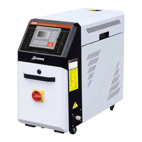
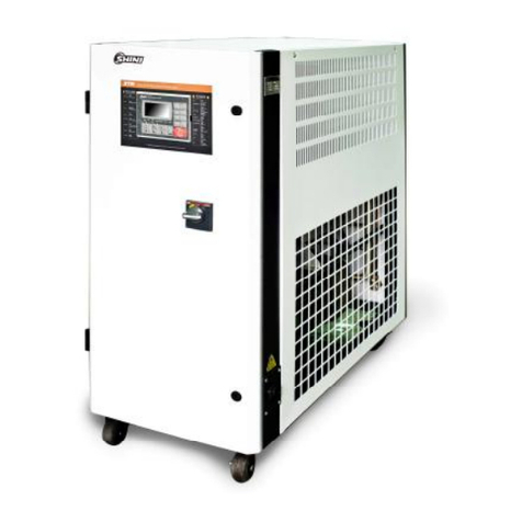
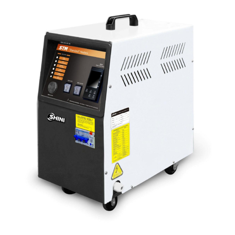
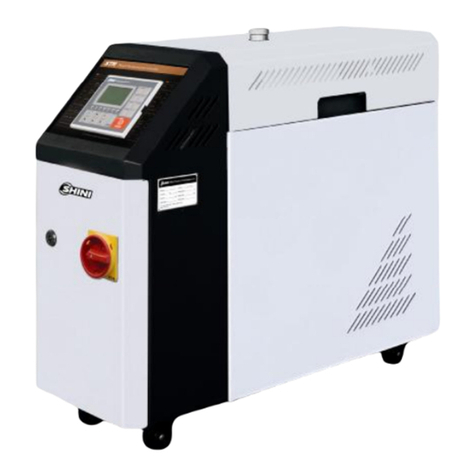
Shini STM-W/O Series User manual

STM-W/O Series
Dual-purpose Water/Oil Heater
Date:Nov. 2014
Version: Ver.B(English)


3(77)
Contents
1. General Description.....................................................................................9
1.1 CodingPrinciple....................................................................................10
1.2 Feature..................................................................................................10
1.3 TechnicalSpecifications........................................................................12
1.3.1 Specification...............................................................................12
1.3.2 PumpPerformance.....................................................................13
1.3.3 ReferenceFormulaofMouldControllersModelSelection..........13
1.4 SafetyRegulations................................................................................14
1.4.1 SafetySignsand Labels.............................................................14
1.4.2 Signsand Labels........................................................................15
1.4.3 OperationRegulations................................................................16
1.4.4 Transportation andStorageoftheMachine................................17
1.5 ExemptionClause.................................................................................18
2. StructureCharacteristics and WorkingPrinciple....................................20
2.1 MainFunctions......................................................................................20
2.1.1 WorkingPrinciple........................................................................20
2.2 AssemblyDrawing................................................................................21
2.2.1 AssemblyDrawing(STM-607/907-W/O).....................................21
2.2.2 PartsList (STM-607W/O)...........................................................22
2.2.3 Oil/waterTankAssembly(STM-607W/O)....................................23
2.2.4 Oil/waterTankPartsList(STM-607W/O)....................................24
2.2.5 Oil/waterTankAssembly(STM-907W/O)...................................25
2.2.6 Oil/waterTankPartsList(STM-907W/0).....................................26
2.2.7 Pipe HeaterAssemblyDrawing(STM-607W/O).........................27
2.2.8 Pipe HeaterPartsList(STM-607W/O).........................................27
2.2.9 Pipe HeaterAssemblyDrawing(STM-907W/O)..........................28
2.2.10Pipe HeaterPartsList(STM-907W/O)........................................28
2.2.11Water-refill ConnectorAssembly(STM-607/907-W/O)...............29
2.2.12Water-refill ConnectorPartsList(STM-607/907-W/O).................29
2.2.13WaterDrainageConnectorAssembly(STM-607/907-W/O)........30
2.2.14WaterDrainageConnectorPartsList(STM-607/907-W/O).........30

4(77)
2.2.15Pump..........................................................................................31
2.3 ElectricalDiagram.................................................................................32
2.3.1 MainCircuit (STM-607W/O)(400V)............................................32
2.3.2 ControlCircuit (STM-607W/O)(400V)........................................33
2.3.3 ElectricalComponentsLayout (STM-607W/O)(400V)...............34
2.3.4 ElectricalComponentsList (STM-607W/O)(400V)....................35
2.3.5 MainCircuit (STM-907W/O)(400V)............................................36
2.3.6 ControlCircuit (STM-907W/O)(400V)........................................37
2.3.7 ElectricalComponentsLayout (STM-907W/O)(400V)...............38
2.3.8 ElectricalComponentsList (STM-907W/O)(400V)....................39
2.3.9 MainCircuit (STM-607W/O)(230V)............................................40
2.3.10ControlCircuit (STM-607W/O)(230V)........................................41
2.3.11ElectricalComponentsLayout (STM-607W/O)(230V)...............42
2.3.12ElectricalComponentsList (STM-607W/O)(230V)....................43
2.3.13MainCircuit (STM-907W/O)(230V)............................................44
2.3.14ControlCircuit (STM-907W/O)(230V)........................................45
2.3.15ElectricalComponentsLayout (STM-907W/O)(230V)...............46
2.3.16ElectricalComponentsList (STM-907W/O)(230V)....................47
2.4 MainElectricalComponentsDescription...............................................48
2.4.1 Overload Relay...........................................................................48
2.5 OperationProcedures...........................................................................49
2.5.1 Installation stepsforoptionswatermanifold(dewaxing).............49
2.5.2 Installation stepsforoptionswatermanifold(welding)................49
3. Installation and Debugging........................................................................51
3.1 Installation Space..................................................................................51
3.2 Mouldand WaterCoupling....................................................................51
3.3 PowerSupply........................................................................................52
4. Operation Guide.........................................................................................53
4.1 ControlPanel........................................................................................53
4.2 Menu Introduction.................................................................................56
4.3 Machine Startup....................................................................................56
4.4 ParameterReferenceTable..................................................................65
4.5 Stop theMachine..................................................................................66
4.6 RenewalofHeatingMedium.................................................................67

5(77)
5. Trouble-shooting........................................................................................68
6. Maintenance and Repair............................................................................70
6.1 OpentheCovers...................................................................................71
6.2 YType Strainer.....................................................................................71
6.3 SolenoidValve......................................................................................72
6.4 Printed Circuit Board.............................................................................72
6.5 DisplayerTerminalConnectingDiagram...............................................75
6.6 MaintenanceSchedule..........................................................................76
6.6.1 About theMachine......................................................................76
6.6.2 Installation &Inspection..............................................................76
6.6.3 DailyChecking............................................................................76
6.6.4 WeeklyChecking........................................................................76
6.6.5 TrimonthlyChecking...................................................................76
6.6.6 Half-yearlyChecking...................................................................76
6.6.7 YearlyChecking..........................................................................77
6.6.8 3yearChecking..........................................................................77
TableIndex
Table1-1 Specification...................................................................................12
Table2-1 PartsList (STM-607W/O)...............................................................22
Table2-2 Oil/waterTankPartsList (STM-607W/O).....................................24
Table2-3 Oil/waterTankPartsList (STM-907W/O).......................................26
Table2-4 PipeHeaterPartsList (STM-607W/O)...........................................27
Table2-5 PipeHeaterPartsList (STM-907W/O)...........................................28
Table2-6 Water-refill ConnectorPartsList (STM-607/907-W/O)...................29
Table2-7 WaterDrainageConnectorPartsList(STM-607/907-W/O)............30
Table2-8 ElectricalComponentsList (STM-607W/O)(400V)........................35
Table2-9 ElectricalComponentsList (STM-907W/O)(400V)........................39
Table2-10 ElectricalComponentsList (STM-607W/O)(230V)......................43
Table2-11 ElectricalComponentsList (STM-907W/O)(230V)......................47
PictureIndex

6(77)
Picture1-1 PumpPerformance......................................................................13
Picture2-1 WorkingPrinciple.........................................................................20
Picture2-2 AssemblyDrawing(STM-607/907-W/O)......................................21
Picture2-3 Oil/waterTankAssembly(STM-607W/O)....................................23
Picture2-4 Oil/waterTankAssembly(STM-907W/O)....................................25
Picture2-5 Pipe HeaterAssemblyDrawing(STM-607W/O)..........................27
Picture2-6 Pipe HeaterAssemblyDrawing(STM-907W/O)..........................28
Picture2-7 Water-refill ConnectorAssemblyDrawing(STM-607/907-W/O)..29
Picture2-8 WaterDrainageConnectorAssemblyDrawing(STM-607/907-W/O)
..........................................................................................................................30
Picture2-9 Pump...........................................................................................31
Picture2-10 MainCircuit (STM-607W/O)(400V)...........................................32
Picture2-11 ControlCircuit (STM-607W/O)(400V).......................................33
Picture2-12 ElectricalComponentsLayout (STM-607W/O)(400V)..............34
Picture2-13 MainCircuit (STM-907W/O)(400V)...........................................36
Picture2-14 ControlCircuit (STM-907W/O)(400V).......................................37
Picture2-15 ElectricalComponentsLayout (STM-907W/O)(400V)..............38
Picture2-16 MainCircuit (STM-607W/O)(230V)...........................................40
Picture2-17 ControlCircuit (STM-607W/O)(230V).......................................41
Picture2-18 ElectricalComponentsLayout (STM-607W/O)(230V)..............42
Picture2-19 MainCircuit (STM-907W/O)(230V)...........................................44
Picture2-20 ControlCircuit (STM-907W/O)(230V).......................................45
Picture2-21 ElectricalComponentsLayout (STM-907W/O)(230V)..............46
Picture2-22 OverloadRelay..........................................................................48
Picture3-1 InstallationSpace........................................................................51
Picture3-2 MouldandWaterCoupling1.......................................................52
Picture3-3 MouldandWaterCoupling2.......................................................52
Picture3-4 MouldandWaterCoupling3.......................................................52
Picture4-1 ControlPanel...............................................................................53
Pictute4-2 MenuOutline................................................................................56
Picture4-3: MainPowerSwitch........................................................................57
Picture4-4: InitialMenu....................................................................................57
Picture4-5: ControlSetting...............................................................................58
Picture4-6: AlarmSetting.................................................................................59

7(77)
Picture4-7: Output Setting...............................................................................60
Picture4-8:TemperatureSetting......................................................................61
Picture4-9:TimeSetting..................................................................................62
Picture4-10: Communication Setting...............................................................63
Picture4-11:Equipment Setting.......................................................................64
Picture4-12: OperationScreen........................................................................65
Picture6-1 Openthe Covers1.......................................................................71
Picture6-2 Openthe Covers2.......................................................................71
Picture6-3 Y Type Strainer............................................................................72
Picture6-4 SolenoidValve.............................................................................72

8(77)

9(77)
1. General Description
Read thismanualcarefullybeforeoperationtopreventdamageofthe
machine orpersonalinjuries.
STM-W/O seriesofdual-purposeheateraremainlyusedtoheatupthemouldand
maintainitstemperature, althoughtheycan bealsousedinothersimilar
applications. Hightemperaturewateroroil returnfromthe mouldiscooledby
indirect coolingand then sent tothe pipe heaterviahigh-pressurepumpfor
heatingtoaconstant temperature.Thisunique designallowsusertochoose
between waterand oil asheat transfermedium.Withouroptimized design, the
HANYOUNG temperaturecontrollercanmaintainan accuracyof 0.5.
Model: STM-907W/O

10(77)
1.1CodingPrinciple
Notes*
CE=CE ConformityB=Buzzer
1.2Feature
1)Standardconfiguration
●Controlleradopts3.2" LCD foreasyoperation.
●Equippedwiththe designof7-dayautomaticstart/stop timer. LCD screen
can be converted between Chineseand English.The unitoftemperaturecan
be converted between oFand .
●P.I.Dmulti-stagetemperaturecontrolsystemcan maintainamould
temperaturewithaccuracyof 0.5.
●Adoptshighefficiency, verticaldual-purposeofwater/oil highpressurepump
toensurestableperformanceand greatpressure.
●Multiplesafetydevicesincludingpowerreversephaseprotection, pump
overload protection, overheatprotectionandlowlevelprotection thatcan
automaticallydetectabnormalperformanceand indicatethisviavisible
alarm.
●Adoptswateroroil ad heatingmedium,themaximumtemperaturecanreach:
wateris95andoil is160.
●Equippedwithpumpreversion evacuation, automaticwatersupplyingand
negativepressureoperation.
●AdoptedEthernet communicationfunctiontorealizecentralmonitoring
online.

11(77)
2)Accessoryoption
●Watermanifolds, teflonhoseandtransferoil areoptional.
●Displaysofmoldtemperatureandreturnwatertemperatureofmoldare
optional.
All serviceworkshouldbe carried out byaperson withtechnicaltrainingor
correspondingprofessionalexperience.The manualcontainsinstructionsforboth
handlingand servicing.Chapter6, whichcontainsserviceinstructionsintendedfor
serviceengineers. Otherchapterscontaininstructionsforthedailyoperator.
Anymodificationsofthemachinemustbe approved bySHINI inordertoavoid
personalinjuryand damagetomachine.Weshall not beliableforanydamage
causedbyunauthorized changeof themachine.
Ourcompanyprovidesexcellent after-salesservice. Shouldyou haveanyproblem
duringusingthemachine,pleasecontactthecompanyorthelocalvendor.
HeadquarterandTaipeifactory
Tel:(886)226809119
ShiniPlastics Technologies(Dongguan), Inc
Tel:(86)769 81116600
ShiniPlastics TechnologiesIndiaPvt.Ltd.
Tel:(91)250 3021166

12(77)
1.3Technical Specifications
1.3.1Specification
Table1-1 Specification
Model Max.
temp.
Pipe
heater
(kw)
Pump
powe
r (kw)
Max.
pump
flow
(L/min)
Max.
pump
pressure
(bar)
Heating
tank
Main/
sub.
oiltank (L)
Cooling
method
Mould
coupling*
(inch)
Inlet /
Outlet
(inch)
Dimensions
(mm)
(H×W×D)
Weight
(kg)
STM-607W/O
6 0.55
55 3.4 1 12 845×325×907
75
STM-907W/O
W:95℃
O: 160℃
W:9
O: 6
0.55
55 3.4 1 16
Indirect
3/8"(2×2)
3/4"/3/4"
832×353×807
84
Note: 1) Pumptestingconditions: Power of50 / 60Hz,We reservethe right tochange
purified water in20℃.( 10 %is tolerable forspecificationswithoutprior notice.
eithermax. flowrateormax. Pressure).
2) "*"standsfor options.
3) Power supply: 3Φ,230 /400/ 460/ 575VAC, 50/60Hz.

13(77)
1.3.2PumpPerformance
Picture1-1 PumpPerformance
1.3.3ReferenceFormulaofMouldControllersModelSelection
HeaterPower(kW)=mouldweight (kg) ×mouldspecificheat (kcal/kg) ×
temperaturedifferencebetween mouldandenvironment() ×safetycoefficient
/ heatingduration / 860
Note: safetycoefficientcan selectavalue from1.3to1.5.
FlowRate(L/min)=heaterpower(kw) ×860 / [heatingmediumspecific
(kcal/kg) ×heatingmediumdensity(kg/L) ×in/outlet temperaturedifference
() ×time(60)]
Note:Waterspecificheat =1kcal/kg
Heatingmediumoil specificheat =0.49kcal/kg
Waterdensity=1kg/L
Heatingmediumoil density=0.842kg/L

14(77)
1.4SafetyRegulations
Strictlyabide bythe followingsafetyregulationstoprevent damageofthe
machine orpersonalinjuries.
1.4.1SafetySignsand Labels
Danger!
Theunit isdesigned toendurehightemp,andhighpressure. Forsafe
operation,do notremovethe coversorswitches.
Attention!
Theunit shouldbe operated byqualifiedpersonnelonly.
Duringoperation, avoidwearingglovesorclothesthatmaycause
danger.
Turnoff mainswitchwhen powersupplyisoff.
Stoptheunitwhentheremaybepowersupplyproblemscausedbystatic
electricity.
Put onsafetyglovesand shoesduringinstallation orrelocation.
Componentsfromourcompanycan onlybe used forreplacement.
Warning!
Donottouchthe switchwithwet object orhands.
Donotusethemachinebeforefullyawareofitsperformance.
Becarefulnot totouchorhit the switchorsensor.
Pleasekeepenoughoperationspace,andkeep awayobstacles.
Toavoidproducingstatics, cleanthefloorfromoil orwatertokeep adry
environment.
Protectthemachineagainst severevibration orcollision.
Donotremovesafetysignsormakeit dirty.
Drunken,medicine-taking, ormen withoutproperjudgement shouldnot
operatethe machine.
Warning!
Hightemperature, takecareof hands! Thislabelisattached on the
surfaceofheatingparts.

15(77)
1.4.2Signsand Labels
Pleaseaccordingtoscheduletomake
regularmaintenance.
Oil dischargevalve: oildischargeport
when machine ischangingoil.
Frommould: connectorforcirculating
water/oil of comingfrommould
Tomold:connectorforcirculatingwater/
oil togotomould.
Oil inlet: Machine oil inlet

16(77)
1.Tomaintaintemperaturestability,
coolingwaterpressuremustbehigher
than2baratall time,but shouldnever
exceed 5barinanycase.
2.Clean Y-shape CoolingWaterStrainer
periodicallytoensureperfectcooling
capacity.
溢流口
Overflowport
Wateroutlet: coolingwateroutlet
Waterinlet: coolingwaterintlet
Highvoltage! Electricalshock may
happen.
Carefulnessisrequired fromthe
operator.
1.4.3OperationRegulations
1)Beforeoperation,makesurethat coolingwateriscleansoft waterwithout
pollutants.
※Lowqualitywaterbringslimescales, whichmaycauseproblems.
2)Ifproblemsof drainageorbadtemperaturecontrolarenoted,pleaseclean
solenoidvalveand coolingwaterinlet and outlet.
3)Donotmovetheunit when it isinoperation.
4)Wheninneed ofrepairing, wait until oil temperaturefallsbelow30℃.
5)Motoroverload maybe causedbyphaseshortage,pipe obstruction,broken
bearing, etc. Motoroverload relaywilltripofftostopthemachine when this
happens.Fixingthe problems, pressRESETon overloadrelaytoclearthe

17(77)
alarm.
6)Beforeturnoff thepump, wait until oil temperaturefallsblow50℃.Orthelife
oftheunit wouldbeaffected.
1.4.4Transportation andStorageoftheMachine
Transportation
1)STM-W/Oseriesarepackedincratesorplywood caseswithwooden palletat
the bottom, suitableforquick positioningbyforklift.
2)Afterunpacked, castorsequipped on the machinecan be usedforeaseof
movement.
3)Donot rotatethemachineandavoidcollision withotherobjectsduring
transportationtoprevent improperfunctioning.
4)The structureofthe machine iswell-balanced,althoughit shouldalsobe
handled withcarewhenliftingthemachineforfearoffallingdown.
5)The machine anditsattachedpartscanbekeptat atemperaturefrom-25
to+55 forlongdistancetransportationandforashort distance, itcan be
transported withtemperatureunder+70 .
Storage
1)STM-W/O seriesshouldbe stored indoorswithtemperaturekept from5 to
40 and humiditybelow80%.
2)Disconnect all powersupplyand turnoffmainswitchand controlswitch.
3)Keepthe wholemachine,especiallythe electricalcomponentsawayfrom
watertoavoidpotentialtroublescaused bythe water.
4)Plasticfilm shouldbeusedtoprotect the machinefromdust and rains.
Workingenvironment
Themachineshouldbeoperated:
1)Indoorsinadryenvironment withmax. temperature+45 andhumidityno
morethan80%.
Donotusethemachine:
1)Ifit iswithadamaged cord.
2)Onawet floororwhen it isexposed toraintoavoidelectricalshock.
3)Ifithasbeendropped ordamaged until it ischeckedorfixed byaqualified

18(77)
serviceman.
4)Thisequipmentworks normallyintheenvironmentwithaltitudewithin3000m.
5)At least aclearanceof1msurroundingthe equipment isrequired during
operation.Keepthisequipment awayfromflammablesourcesat least two
meters.
6)Avoidvibration, magneticdisturbanceat theoperationarea.
Rejectedpartsdisposal
When the equipmenthasrun out itslifetimeand can notbe usedanymore,
unplugthepowersupplyand disposeof it properlyaccordingtolocalcode.
FireHazard
Incaseoffire, Co2drypowderfireextinguishershouldbeapplied.
Pleaseabidebythesafetyguide whenyou operatethe machinesoasto
prevent damageofthemachine andpersonalinjuries.
All electricalcomponentsshouldbe installedbyqualified electricians.
Turnoff mainswitchand controlswitchduring repair and maintenance.
Warning! Highvoltage!
Thismarkisattachedon the coverof thecontrolbox.
Warning! Becareful!
Be morecarefulwhen thismarkappears.
Warning!
Hightemperature, takecareof hands! Thislabelisattached on the
surfaceofheatingparts.
1.5 Exemption Clause
Thefollowingstatementsclarifytheresponsibilitiesandregulationsbornbyany
buyeroruserwho purchasesproductsandaccessoriesfromShini(including
employeesandagents).
Shiniisexempted fromliabilityforanycosts,fees,claimsandlossescausedby

19(77)
reasonsbelow:
1. Anycarelessorman-madeinstallations,operation andmaintenancesupon
machineswithoutreferringtothe Manualpriortomachineusing.
2. Anyincidentsbeyondhumanreasonablecontrols, whichincludeman-made
viciousordeliberatedamagesorabnormalpower,and machine faultscaused
byirresistiblenaturaldisastersincludingfire,flood,stormand earthquake.
3. Anyoperationalactionsthatarenotauthorized byShiniuponmachine,
includingaddingorreplacingaccessories, dismantling,deliveringorrepairing.
4. Employingconsumablesoroil mediathatarenotappointed byShini.

20(77)
2. Structure Characteristics andWorkingPrinciple
2.1MainFunctions
STM-W/O seriesof dual-purposeheateraremainlyused toheat up the
mouldand maintainitstemperature,although theycan be alsousedinother
similarapplications.Hightemperaturewateroroil returnfromthemouldis
cooledbyindirect coolingand thensent tothe pipe heaterviahigh-pressure
pumpforheatingtoaconstant temperature.Thisunique designallowsuserto
choosebetween waterandoil asheat transfermedium.Withouroptimised
design, theOMRONtemperaturecontrollercan maintainan accuracyof 1.
2.1.1WorkingPrinciple
Picture2-1 WorkingPrinciple
Hightemperaturewaterreturnstothemachineandthenbepressured bypump
totheheater.Afterbeingheated,waterwill beforcedtomouldand continue the
circle. Intheprocess, if the temperatureistoohigh, thesystemwill activatethe
solenoidvalvetolet coolingwatercooldownthe temp. directlytill the water
temp. isdowntothe systemrequirement. Ifthetemp.keeprisingandreachto
the set pointofEGO, the systemwill alarmand stop operation.Thesystemwill
havelowpressurealarmand stop workingifcoolingwaterpressuredoesn’t
reachset point.
Other manuals for STM-W/O Series
1
This manual suits for next models
2
Table of contents
Other Shini Heater manuals
Popular Heater manuals by other brands

RHINO
RHINO TQ3 quick start guide

L.B. White
L.B. White CP350AK owner's manual

Detroit Radiant Products
Detroit Radiant Products HLV Series Design, Installation, Operation, and Maintenance Manual

Widney
Widney Revo installation instructions

Adax
Adax NEO S5.1 user guide

Goldair
Goldair GFE340 operating instructions

Geberit
Geberit Pluvia 359.971.00.1 installation manual

DeWalt
DeWalt DXKH080E instruction manual

ARDES
ARDES AR4R09 Instructions for use

Empire Comfort Systems
Empire Comfort Systems BF-10-2 Installation instructions and owner's manual

Holmes
Holmes HFH442 owner's guide

Frico
Frico Panther PNF06 Original instructions