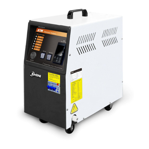
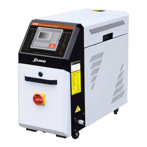
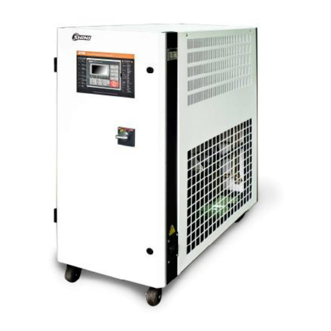
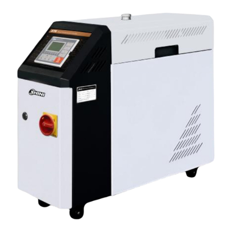
Shini STM-HT Series User manual

STM-HTSeries
Hi-temp.Oil Heater
Date:Nov, 2014
Version: Ver.B(English)


3(77)
Contents
1. General Description..................................................................................7
1.1 CodingPrinciple...................................................................................8
1.2 Feature.................................................................................................8
1.3 TechnicalSpecifications.....................................................................10
1.3.1 Specification............................................................................10
1.3.2 PumpPerformance..................................................................11
1.3.3 ReferenceFormulaofMouldControllersModelSelection.......12
1.4 SafetyRegulations.............................................................................13
1.4.1 SafetySignsand Labels..........................................................13
1.4.2 Signsand Labels.....................................................................14
1.4.3 OperationRegulations.............................................................15
1.4.4 Transportation andStorageoftheMachine.............................16
1.5 ExemptionClause..............................................................................17
2. StructureCharacteristics and WorkingPrinciple.................................19
2.1 WorkingPrinciple...............................................................................19
2.2 AssemblyDrawing.............................................................................20
2.2.1 AssemblyDrawing(STM-907/1215-HT)..................................20
2.2.2 PartsList (STM-907/1215-HT).................................................21
2.2.3 AssemblyDrawing(STM-2440-HT).........................................23
2.2.4 PartsList (STM-2440-HT)........................................................24
2.2.5 Pump.......................................................................................26
2.3 ElectricalDiagram..............................................................................27
2.3.1 MainCircuit (STM-907/1215-HT400V)...................................27
2.3.2 ControlCircuit (STM-907/1215-HT400V)................................28
2.3.3 ElectricalComponentsLayout (STM-907/1215-HT400V).......29
2.3.4 ElectricalComponentsList (STM-907/1215-HT400V)............30
2.3.5 MainCircuit (STM-2440-HT400V)..........................................32
2.3.6 ControlCircuit (STM-2440-HT400V).......................................33
2.3.7 ElectricalComponentsLayout (STM-2440-HT400V)..............34
2.3.8 ElectricalComponentsList (STM-2440-HT400V)...................35
2.3.9 MainCircuit (STM-907/1215-HT230V)...................................36

4(77)
2.3.10ControlCircuit (STM-907/1215-HT230V)................................37
2.3.11ElectricalComponentsLayout (STM-907/1215-HT230V).......38
2.3.12ElectricalComponentsList (STM-907/1215-HT230V)............39
2.3.13MainCircuit (STM-2440-HT230V)..........................................41
2.3.14ControlCircuit (STM-2440-HT230V).......................................42
2.3.15ElectricalComponentsLayout (STM-2440-HT230V)..............43
2.3.16ElectricalComponentsList (STM-2440-HT230V)...................44
2.4 MainElectricalComponentsDescription............................................45
2.4.1 Overload Relay........................................................................45
2.5 OperationProcedures........................................................................46
2.5.1 Installation stepsforoptionswatermanifold(dewaxing)..........46
2.5.2 Installation stepsforoptionswatermanifold(welding).............46
3. Installation and Debugging.....................................................................48
3.1 Installation Space...............................................................................48
3.2 Mouldand WaterCoupling.................................................................49
3.3 PowerSupply.....................................................................................50
4. Operation Guide......................................................................................51
4.1 ControlPanel.....................................................................................51
4.2 Menu Introduction..............................................................................54
4.3 Machine Startup.................................................................................54
4.4 ParameterReferenceTable...............................................................63
4.5 Stop theMachine...............................................................................64
5. Trouble-shooting.....................................................................................66
6. Maintenance and Repair.........................................................................68
6.1 OpentheCovers................................................................................69
6.2 YType Strainer..................................................................................69
6.3 SolenoidValve...................................................................................70
6.4 Pipe Heater........................................................................................70
6.5 CoolingPipes.....................................................................................71
6.6 Printed Circuit Board..........................................................................72
6.7 DisplayerTerminalConnectingDiagram............................................75
6.8 MaintenanceSchedule.......................................................................76
6.8.1 About theMachine...................................................................76

5(77)
6.8.2 Installation &Inspection...........................................................76
6.8.3 DailyChecking.........................................................................76
6.8.4 WeeklyChecking.....................................................................76
6.8.5 TrimonthlyChecking................................................................76
6.8.6 Half-yearlyChecking................................................................76
6.8.7 YearlyChecking.......................................................................77
6.8.8 3yearChecking.......................................................................77
TableIndex
Table1-1 Specification...................................................................................10
Table2-1 PartsList (STM-907-HT)................................................................21
Table2-2 PartsList (STM-1215-HT)..............................................................22
Table2-3 PartsList (STM-2440)....................................................................24
Table2-4 ElectricalComponentsList (STM-907-HT400V)...........................30
Table2-5 ElectricalComponentsList (STM-1215-HT400V).........................31
Table2-6 ElectricalComponentsList (STM-2440-HT400V).........................35
Table2-7 ElectricalComponentsList (STM-907-HT230V)...........................39
Table2-8 ElectricalComponentsList (STM-1215-HT230V).........................40
Table2-9 ElectricalComponentsList (STM-2440-HT230V).........................44
PictureIndex
Picture1-1 PumpPerformance......................................................................11
Picture2-1 WorkingPrinciple.........................................................................19
Picture2-2 AssemblyDrawing(STM-907/1215-HT)......................................20
Picture2-3 AssemblyDrawing(STM-2440-HT).............................................23
Picture2-4 Pump...........................................................................................26
Picture2-5 MainCircuit (STM-907/1215-HT400V)........................................27
Picture2-6 ControlCircuit (STM-907/1215-HT400V)....................................28
Picture2-7 ElectricalComponentsLayout (STM-907/1215-HT400V)...........29
Picture2-8 MainCircuit (STM-2440-HT400V)..............................................32
Picture2-9 ControlCircuit (STM-2440-HT400V)...........................................33
Picture2-10 ElectricalComponentsLayout (STM-2440-HT400V)................34

6(77)
Picture2-11 MainCircuit (STM-907/1215-HT230V)......................................36
Picture2-12 ControlCircuit (STM-907/1215-HT230V)..................................37
Picture2-13 ElectricalComponentsLayout (STM-907/1215-HT230V).........38
Picture2-14 MainCircuit (STM-2440-HT230V)............................................41
Picture2-15 ControlCircuit (STM-2440-HT230V).........................................42
Picture2-16 ElectricalComponentsLayout (STM-2440-HT230V)................43
Picture2-17 OverloadRelay..........................................................................45
Picture3-1 InstallationSpace........................................................................48
Picture3-2 MouldandWaterCoupling1.......................................................49
Picture3-3 MouldandWaterCoupling2.......................................................49
Picture3-4 MouldandWaterCoupling3.......................................................50
Picture4-1 ControlPanel...............................................................................51
Pictute4-2 MenuOutline................................................................................54
Picture4-3: MainPowerSwitch........................................................................55
Picture4-4: InitialMenu....................................................................................55
Picture4-5: ControlSetting...............................................................................56
Picture4-6: AlarmSetting.................................................................................57
Picture4-7: Output Setting...............................................................................58
Picture4-8:TemperatureSetting......................................................................59
Picture4-9:TimeSetting..................................................................................60
Picture4-10: Communication Setting...............................................................61
Picture4-11:Equipment Setting.......................................................................62
Picture4-12: OperationScreen........................................................................63
Picture6-1 Openthe Covers1.......................................................................69
Picture6-2 Openthe Covers2.......................................................................69
Picture6-3 Openthe Covers3.......................................................................69
Picture6-4 Y Type Strainer............................................................................70
Picture6-5 SolenoidValve.............................................................................70
Picture6-6 Pipe Heater1...............................................................................71
Picture6-7 Pipe Heater2...............................................................................71
Picture6-8 Pipe Heater3...............................................................................71
Picture6-9 CoolingPipes1............................................................................72
Picture6-10 CoolingPipes2..........................................................................72

7(77)
1.General Description
Read thismanualcarefullybeforeoperationtopreventdamageofthe
machine orpersonalinjuries.
STM-HTserieshightemperatureoil heaterareusedtoheatup the mouldand
maintaintemperature,althoughtheycanbeused inothersimilarapplications.
Hightemperatureoil fromthe mouldisreturned tothecoolingtankand cooledby
indirect cooling. It isthen pressurised bythe high-pressurepump,sent tothe
heatingtankandfinallytothe mouldwithaconstant temperature.Withour
optimised design, Itcanreachamaximumof300andthe HANYOUNG
temperaturecontrollercan maintainanaccuracyof 1.
Model: STM-2440HT

8(77)
1.1CodingPrinciple
Notes*
D=Dual-heatingZonesHT=HighTemperatureModel
CE=CE ConformityB=Buzzer
1.2Feature
1)Standardconfiguration
●Controlleradopts3.2" LCD foreasyoperation.
●Equippedwiththe designof7-dayautomaticstart/stop timer. LCD screen
can beconverted between ChineseandEnglish.Theunitoftemperature
can beconverted between oFand .
●P.I.D.multi-stagetemperaturecontrolsystemcan maintainamould
temperaturewithaccuracyof 0.5 .
●Adoptshighefficiencyhightemperaturepump,whichcanmeetthedemands
oftemperaturecontrolforprecisemouldsandmouldloop withminor
diametertoachieveprecisetemperaturecontroland highefficientheat
exchange.
●Multiplesafetydevicesincludingpowerreversephaseprotection, pump
overload protection, overheatprotectionandlowlevelprotection thatcan
automaticallydetectabnormalperformanceand indicatethisviavisible
alarm.
●Pipe heateraremade of stainless steel.
●WhileforSTM-HT,it can reach300 .
●Insidetankof STM-HTismadeof highpressureresistancestainless steelto
prevent anyexplosion.

9(77)
2)Accessoryoption
●Watermanifolds,Teflon hoseandTransferoil areoptional.
●RS485 communication functionisoptional.Displayofmouldtemperature
and mouldreturnwatertemperatureisoptional.
All serviceworkshouldbe carried out byaperson withtechnicaltrainingor
correspondingprofessionalexperience.The manualcontainsinstructionsforboth
handlingand servicing.Chapter6, whichcontainsserviceinstructionsintendedfor
serviceengineers. Otherchapterscontaininstructionsforthedailyoperator.
Anymodificationsofthemachinemustbe approved bySHINI inordertoavoid
personalinjuryand damagetomachine.Weshall not beliableforanydamage
causedbyunauthorized changeof themachine.
Ourcompanyprovidesexcellent after-salesservice. Shouldyou haveanyproblem
duringusingthemachine,pleasecontactthecompanyorthelocalvendor.
HeadquarterandTaipeifactory
Tel:(886)226809119
ShiniPlastics Technologies(Dongguan), Inc
Tel:(86)769 81116600
ShiniPlastics TechnologiesIndiaPvt.Ltd.
Tel:(91)250 3021166

10(77)
1.3Technical Specifications
1.3.1Specification
Table1-1 Specification
Model Max.
Temp.
Pipe
Heater
(kW)
Pump
Power
(kW)
(50 / 60Hz)
Max.pump
Flow
(L / min)
(50 / 60Hz)
Max.pump
Pressure
(bar)
(50 / 60Hz)
Heating
Tank
Number
Main/ Sub.
OilTank (L)
Cooling
Method
Mould
Coupling*
(inch)
Inlet/Outlet
(inch)
Dimensions
(mm)
(H×W×D)
Weight
(kg)
STM-907-HT
9 0.5 28 4.8 1 6 / 6 3/8"(2×2)
3/4 / 3/4
695×280×740
75
STM-1215-HT
12 1.0 58 5.8 1 6.8 / 16 1"(1×2)
1 / 1 795×340×820
100
STM-2440-HT
300℃
24 2.8 100 8 2 16 / 25
Indirect
1"(1×2)
1 / 1 1050×515×910
190
Note:1)"HT"standsforhigh temperaturemodel.Wereservethe righttochange
2) Pumptestingstandard: Power of 50 / 60Hz,specificationswithout prior notice.
purified water at20℃.( Thereis 10%tolerance
for eithermax. flowrateor max. pressure).
3) "*"Standsforoptions.
4) Power supply: 3Φ,230 /400/ 460/ 575VAC, 50/ 60Hz.

11(77)
1.3.2PumpPerformance
Flowrate
(L/min)
Pressure
(bar)
0
1
10 20 30 40 50 60 70 80 90 100
2
3
4
5
6
7
8
9
10
1
1
STM-2440HT
STM-907HT
STM-1215HT
Picture1-1 PumpPerformance

12(77)
1.3.3ReferenceFormulaofMouldControllersModelSelection
HeaterPower(kW)=mouldweight (kg) ×mouldspecificheat (kcal/kg ) ×
temperaturedifferencebetween mouldandenvironment( ) ×safetycoefficient
/ heatingduration / 860
Note: safetycoefficientcan selectavalue from1.3to1.5.
FlowRate(L/min)=heaterpower(kw) ×860 /[heatingmediumspecific(kcal/kg
) ×heatingmediumdensity(kg/L)×in/outlettemperaturedifference( )×time
(60)]
Note:Waterspecificheat =1kcal/kg
Heatingmediumoil specificheat =0.49kcal/kg
Waterdensity=1kg/L
Heatingmediumoil density=0.842kg/L

13(77)
1.4SafetyRegulations
Strictlyabide bythe followingsafetyregulationstoprevent damageofthe
machine orpersonalinjuries.
1.4.1SafetySignsand Labels
Danger!
Theunit isdesigned toendurehightemp,andhighpressure. Forsafe
operation,do notremovethe coversorswitches.
Attention!
Theunit shouldbe operated byqualifiedpersonnelonly.
Duringoperation, avoidwearingglovesorclothesthatmaycause
danger.
Turnoff mainswitchwhen powersupplyisoff.
Stoptheunitwhentheremaybepowersupplyproblemscausedbystatic
electricity.
Put onsafetyglovesand shoesduringinstallation orrelocation.
Componentsfromourcompanycan onlybe used forreplacement.
Warning!
Donottouchthe switchwithwet object orhands.
Donotusethemachinebeforefullyawareofitsperformance.
Becarefulnot totouchorhit the switchorsensor.
Pleasekeepenoughoperationspace,andkeep awayobstacles.
Toavoidproducingstatics, cleanthefloorfromoil orwatertokeep adry
environment.
Protectthemachineagainst severevibration orcollision.
Donotremovesafetysignsormakeit dirty.
Drunken,medicine-taking, ormen withoutproperjudgement shouldnot
operatethe machine.
Warning!
Hightemperature, takecareof hands! Thislabelisattached on the
surfaceofheatingparts.

14(77)
1.4.2Signsand Labels
Clean the filterscreen ofYtype strainer
timelytoavoidobstruction whichmay
affectmachineperformance.
It isusedforoil heater.Max. temperature
settingofthisunit is200 .
Thisistoindicatemotorrotating
direction.
When phasereversalhappens, thealarm
soundsandindicatoroncontrolpanelwill
indicate. Pleaseexchangetheplaceof
twooftheelectricalwirestosolvethis
problem.
Highvoltage! Electricalshock may
happen.
Carefulnessisrequired fromthe
operator.
Attentions!
Thisisgeneralwarningswhichoperators
shouldpayattentionto.
Frommould: connectorforcirculating
water/oil comingfrommould.
Pumppressuremeter:indicatingactual
pressureofsystem.

15(77)
Tomold: connectorforcirculatingwater/
oil togotomould.
1.Tomaintaintemperatureconsistency,
coolingwaterpressuremustbehigher
than2baratall time,but shouldnever
exceed 5barinanycase.
2. CleanY-shape CoolingWaterStrainer
periodicallytoensureperfect cooling
capacity.
Waterinlet: inletforreplenishingwater
and coolingwater.
Wateroutlet: drainageoutlet.
1.4.3OperationRegulations
1)Beforeoperation,makesurethat coolingwateriscleansoft waterwithout
pollutants.
※Lowqualitywaterbringslimescales, whichmaycauseproblems.
2)Ifproblemsof drainageorbadtemperaturecontrolarenoted,pleaseclean
solenoidvalveand coolingwaterinlet and outlet.
3)Donotmovetheunit when it isinoperation.
4)Wheninneed ofrepairing, wait until oil temperaturefallsbelow30℃.
5)Motoroverload maybe causedbyphaseshortage,pipe obstruction,broken
bearing, etc. Motoroverload relaywilltripofftostopthemachine when this
happens.Fixingthe problems, pressRESETon overloadrelaytoclearthe
alarm.
6)Beforeturnoff thepump, wait until oil temperaturefallsblow50℃.Orthelife
oftheunit wouldbeaffected.
7)Pleasefirstlyopen coolingwaterbeforestart the machine, andclosecooling

16(77)
waterafterstopthe machine.
1.4.4Transportation andStorageoftheMachine
Transportation
1)STM-HTserieshi-temp.oil heaterarepacked incratesorplywood caseswith
wooden pallet at thebottom, suitableforquickpositioningbyforklift.
2)Afterunpacked, castorsequipped on the machinecan be usedforeaseof
movement.
3)Donot rotatethemachineandavoidcollision withotherobjectsduring
transportationtoprevent improperfunctioning.
4)Thestructureofthe machine iswell-balanced,althoughit shouldalsobe
handled withcarewhenliftingthemachineforfearoffallingdown.
5)The machine anditsattachedpartscanbekeptat atemperaturefrom-25℃
to+55℃forlongdistancetransportationandforashort distance, itcan be
transported withtemperatureunder+70℃.
Storage
1)STM-HTserieshi-temp.oil heatershouldbestoredindoorswithtemperature
keptfrom5OCto40OCand humiditybelow80%.
2)Disconnect all powersupplyand turnoffmainswitchand controlswitch.
3)Keepthe wholemachine,especiallythe electricalcomponentsawayfrom
watertoavoidpotentialtroublescaused bythe water.
4)Plasticfilm shouldbeusedtoprotect the machinefromdust and rains.
Workingenvironment
Themachineshouldbeoperated:
1)Indoorsinadryenvironment withmax. temperature+45℃and humidityno
morethan80%.
Donotusethemachine:
1)Ifit iswithadamaged cord.
2)Onawet floororwhen it isexposed toraintoavoidelectricalshock.
3)Ifithasbeendropped ordamaged until it ischeckedorfixed byaqualified
serviceman.

17(77)
4)Thisequipmentworks normallyintheenvironmentwithaltitudewithin3000m.
5)At least aclearanceof1msurroundingthe equipment isrequired during
operation.Keepthisequipment awayfromflammablesourcesat least two
meters.
6)Avoidvibration, magneticdisturbanceat theoperationarea.
Rejectedpartsdisposal
When the equipmenthasrun out itslifetimeand can notbe usedanymore,
unplugthepowersupplyand disposeof it properlyaccordingtolocalcode.
FireHazard
Incaseoffire, Co2drypowderfireextinguishershouldbe applied.
Pleaseabidebythesafetyguide when you operatethemachinesoasto
prevent damageofthemachine andpersonalinjuries.
All electricalcomponentsshouldbe installedbyqualified electricians.
Turnoff mainswitchand controlswitchduring repair and maintenance.
Warning! Highvoltage!
Thismarkisattachedon the coverof thecontrolbox.
Warning! Becareful!
Be morecarefulwhen thismarkappears.
Warning!
Hightemperature, takecareof hands! Thislabelisattached on the
surfaceofheatingparts.
1.5 Exemption Clause
Thefollowingstatementsclarifytheresponsibilitiesandregulationsbornbyany
buyeroruserwho purchasesproductsandaccessoriesfromShini(including
employeesandagents).
Shiniisexempted fromliabilityforanycosts,fees,claimsandlossescausedby

18(77)
reasonsbelow:
1. Anycarelessorman-madeinstallations,operation andmaintenancesupon
machineswithoutreferringtothe Manualpriortomachineusing.
2. Anyincidentsbeyondhumanreasonablecontrols, whichincludeman-made
viciousordeliberatedamagesorabnormalpower,and machine faultscaused
byirresistiblenaturaldisastersincludingfire,flood,stormand earthquake.
3. Anyoperationalactionsthatarenotauthorized byShiniuponmachine,
includingaddingorreplacingaccessories, dismantling,deliveringorrepairing.
4. Employingconsumablesoroil mediathatarenotappointed byShini.

19(77)
2. Structure Characteristics andWorkingPrinciple
2.1WorkingPrinciple
Picture2-1 Working Principle
Thehightemperatureoil returnstothe machine and thenbepressured by
pumptotheheater. Afterbeingheated,oil willbe forced tothe mouldand
continue the circle.Inthe process, iftheoil temperatureistoohigh,systemwill
activatethesolenoidvalvetolet coolingwatercooldownhightemperatureoil
indirectlyuntil thetemperatureisdowntothe systemrequirement. Ifthe
temperaturekeepsincreasingandreachestothe set pointofEGO, the system
will sound alarmandstop operation.The systemwill havelowlevelalarmand
stop workingifoil levelfallsdownbelowthe set point.

20(77)
2.2AssemblyDrawing
2.2.1AssemblyDrawing(STM-907/1215-HT)
Remarks:Please refertomateriallist2.2.2forspecificexplanation ofthe Arabicnumbersin
partsdrawing.
Picture2-2 AssemblyDrawing (STM-907/1215-HT)
This manual suits for next models
3
Table of contents
Other Shini Heater manuals
Popular Heater manuals by other brands

Bionaire
Bionaire BCH4130 instruction manual

Hozelock Cyprio
Hozelock Cyprio 3539 manual

BILT HARD
BILT HARD FAH-K80 User's manual and operating instructions

Weber
Weber R272TC operating manual

cecotec
cecotec READY WARM FORCE ROTATE 9890 instruction manual

HeatStar
HeatStar ERXL-40 Operating instructions and owner's manual