Shini STM-W/O Series User manual

STM-W/O Series
Dual-purpose Water/ Oil Heater
Date:Oct. 2017
Version:Ver.F(English)


3(47)
Contents
1. General Description..................................................................................... 7
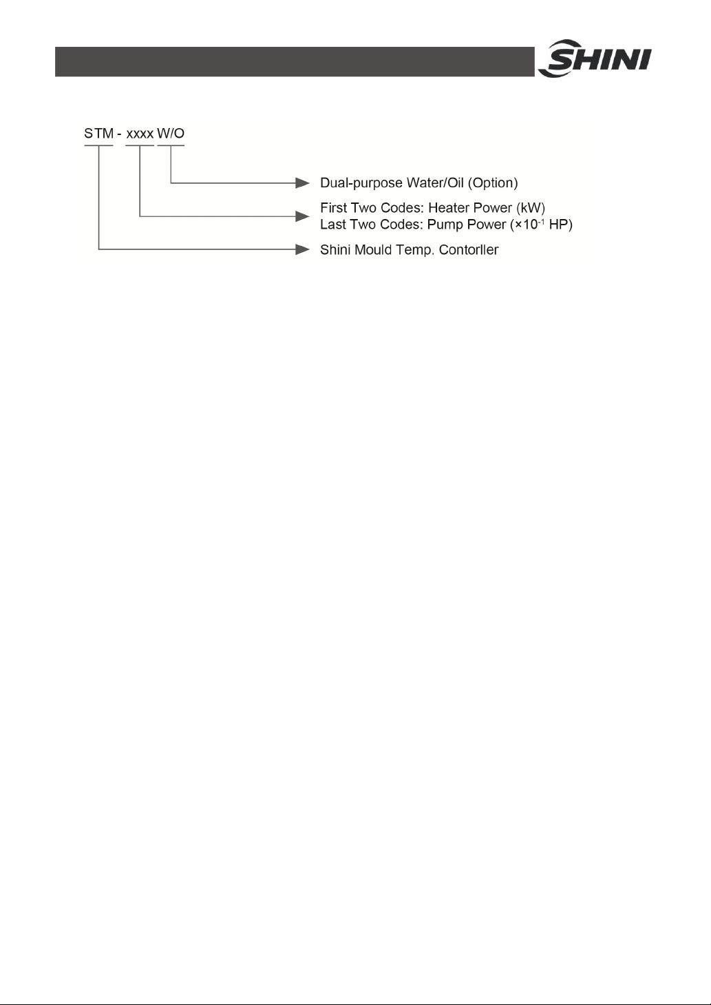
1.1 CodingPrinciple......................................................................................8
1.2 Feature....................................................................................................8
1.3 Accessoryoption.....................................................................................8
1.4 TechnicalSpecifications........................................................................ 10
1.4.1 Specification............................................................................... 10
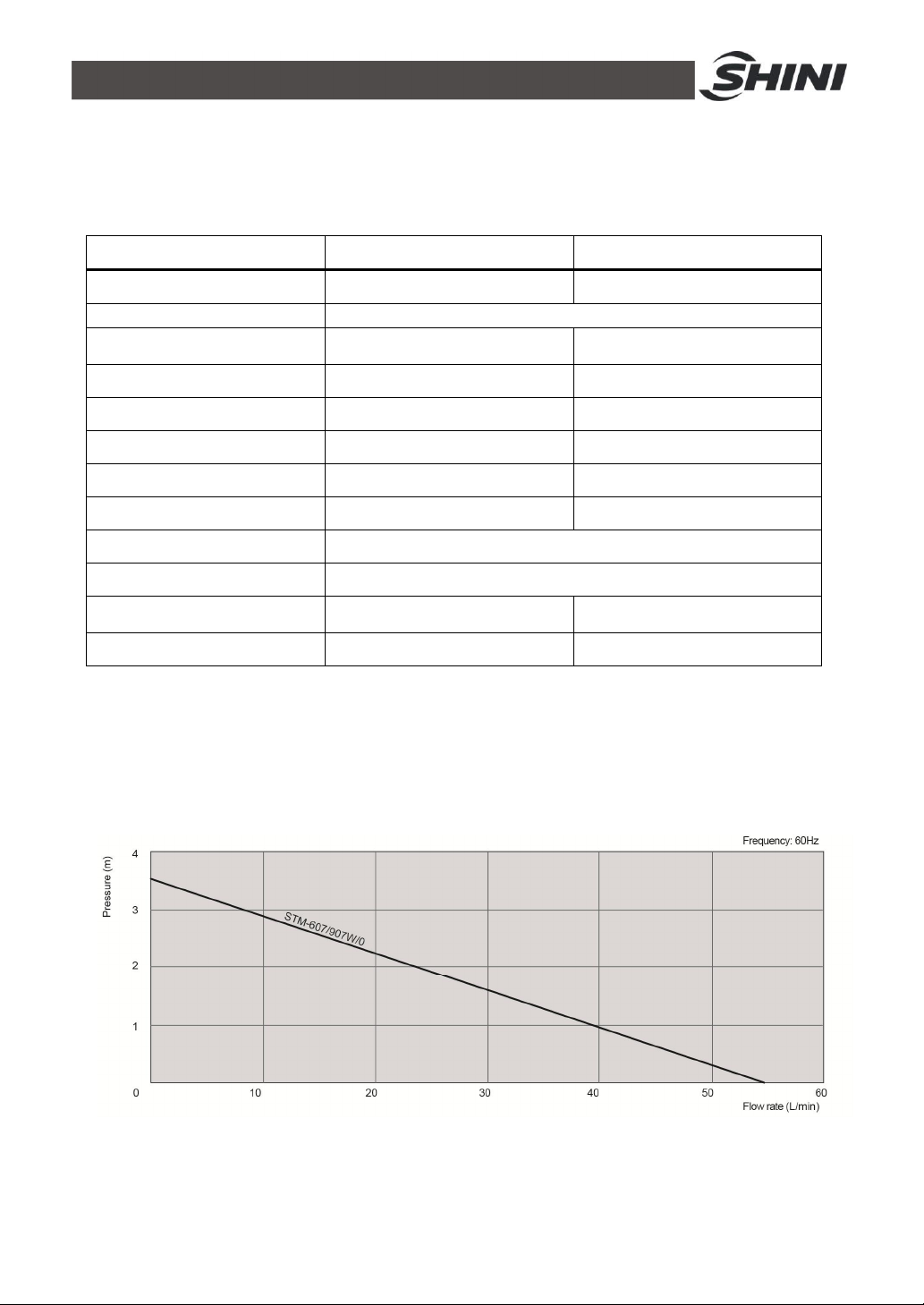
1.4.2 PumpPerformance..................................................................... 10
1.4.3 ReferenceFormulaofMouldControllersModelSelection.......... 11
1.5 SafetyRegulations................................................................................ 11
1.5.1 SafetySignsand Labels............................................................. 11
1.5.2 Signsand Labels........................................................................ 12
1.5.3 OperationRegulations................................................................ 14
1.5.4 Transportation andStorageoftheMachine................................ 14
1.6 ExemptionClause................................................................................. 16
2. StructureCharacteristics and WorkingPrinciple.................................... 17
2.1 MainFunctions...................................................................................... 17
2.1.1 WorkingPrinciple........................................................................ 17
3. Installation and Debugging........................................................................ 19
3.1 Installation Space.................................................................................. 19
3.2 Mouldand WaterCoupling.................................................................... 19
3.3 PowerSupply........................................................................................ 20
3.4 OptionsInstallation................................................................................ 21
3.4.1 Installation stepsforoptionswatermanifold(dewaxing)............. 21
3.4.2 Installation stepsforoptionswatermanifold(welding)................ 21
4. Operation Guide......................................................................................... 23
4.1 ControlPanel........................................................................................ 23
4.2 Menu Introduction................................................................................. 26
4.3 Machine Startup.................................................................................... 27
4.4 Stop theMachine .................................................................................. 37

4(47)
5. Trouble-shooting ........................................................................................ 38
6. Maintenance and Repair............................................................................ 40
6.1 OpentheCovers................................................................................... 41
6.2 YType Strainer..................................................................................... 41
6.3 SolenoidValve...................................................................................... 42
6.4 Printed Circuit Board............................................................................. 43
6.5 DisplayerTerminalConnectingDiagram............................................... 45
6.6 MaintenanceSchedule.......................................................................... 46
6.6.1 About theMachine...................................................................... 46
6.6.2 Installation &Inspection.............................................................. 46
6.6.3 DailyChecking............................................................................ 46
6.6.4 WeeklyChecking........................................................................ 46
6.6.5 TrimonthlyChecking................................................................... 46
6.6.6 Half-yearlyChecking................................................................... 46
6.6.7 YearlyChecking.......................................................................... 47
6.6.8 3yearChecking.......................................................................... 47
TableIndex
Table1-1: Specification.................................................................................... 10
Table4-1: ControlPanel................................................................................... 23
Table4-2: ErrorType........................................................................................ 25
PictureIndex
Picture1-1: PumpPerformance....................................................................... 10
Picture2-1:WorkingPrinciple.......................................................................... 17
Picture3-1: Installation Space.......................................................................... 19
Picture3-2: Mouldand WaterCoupling1......................................................... 19
Picture3-3: Mouldand WaterCoupling2......................................................... 20
Picture3-4: Mouldand WaterCoupling3......................................................... 20
Picture4-1: ControlPanel................................................................................. 23
Pictute4-2: Menu Outline................................................................................. 26

5(47)
Picture4-3: MainPowerSwitch........................................................................ 27
Picture4-4: InitialMenu.................................................................................... 27
Picture4-5: ControlSettingScreen.................................................................. 28
Picture4-6: AlarmSettingScreen..................................................................... 29
Picture4-7: Output SettingScreen................................................................... 30
Picture4-8:TemperatureSettingScreen......................................................... 32
Picture6-1: Open theCovers1........................................................................ 41
Picture6-2: Open theCovers2........................................................................ 41
Picture6-3: YType Strainer............................................................................. 42
Picture6-4: SolenoidValve.............................................................................. 42

6(47)

7(47)
1. General Description
Read thismanualcarefullybeforeoperationtopreventdamageofthe
machine orpersonalinjuries.
STM-W/O seriesofdual-purposeheateraremainlyused toheatupthemould
and maintainitstemperature,althoughtheycan bealsoused inothersimilar
applications.Hightemperaturewateroroil returnfromthemouldiscooledby
indirectcoolingandthen senttothe pipe heaterviahigh-pressurepumpfor
heatingtoaconstanttemperature.Thisunique designallowsusertochoose
between waterand oil asheattransfermedium.Withouroptimized design,the
HANYOUNG temperaturecontrollercanmaintainanaccuracyof 0.5 .
Model: STM-907W/O

8(47)
1.1CodingPrinciple
1.2Feature
lControlleradopts3.2" LCD foreasyoperation.
lEquippedwiththe designof7-dayautomaticstart/stoptimer. LCD screen
can beconverted between ChineseandEnglish.Theunitoftemperature
can beconverted between oFand .
lP.I.Dmulti-stagetemperaturecontrolsystemcan maintainamould
temperaturewithaccuracyof 0.5 .
lAdoptshighefficiency, verticaldual-purposeofwater/oil highpressure
pumptoensurestableperformanceand greatpressure.
lMultiplesafetydevicesincludingpowerreversephaseprotection,pump
overload protection, overheatprotectionandlowlevelprotection thatcan
automaticallydetectabnormalperformanceand indicatethisviavisible
alarm.
lAdoptswateroroil adheatingmedium, themaximumtemperaturecan
reach: wateris95 and oil is160 .
lEquippedwithpumpreversion evacuation,automaticwatersupplyingand
negativepressureoperation.
lAdoptedEthernet communicationfunctiontorealizecentralmonitoring
online.
1.3Accessoryoption
lWatermanifolds, teflonhoseandtransferoil areoptional.
lDisplaysofmoldtemperatureandreturnwatertemperatureofmoldare
optional.
lBuzzerisoptional.Add “B”at themodelbehind.

9(47)
All serviceworkshouldbe carried out byaperson withtechnicaltrainingor
correspondingprofessionalexperience.The manualcontainsinstructionsforboth
handlingand servicing.Chapter6, whichcontainsserviceinstructionsintendedfor
serviceengineers. Otherchapterscontaininstructionsforthedailyoperator.
Anymodificationsofthemachinemustbe approved bySHINI inordertoavoid
personalinjuryand damagetomachine.Weshall not beliableforanydamage
causedbyunauthorized changeof themachine.
Ourcompanyprovidesexcellent after-salesservice. Shouldyou haveanyproblem
duringusingthemachine,pleasecontactthecompanyorthelocalvendor.
HeadquarterandTaipeifactory
Tel:(886)226809119
ShiniPlastics Technologies(Dongguan), Inc
Tel:(86)769 81116600
ShiniPlastics TechnologiesIndiaPvt.Ltd.
Tel:(91)250 3021166

10(47)
1.4Technical Specifications
1.4.1Specification
Table1-1: Specification
Model STM-607W/O STM-907W/O
Ver.` F F
Max. temp. W: 95 O: 160
Pipe heater(kw) 6 W: 9
O: 6
Pumppower (kw) 0.55 0.55
Max. pumpflow(L/min) 55 55
Max. pumppressure(bar) 3.4 3.4
Heatingtank 1 1
Main / sub.oil tank(L) 12 16
Coolingmethod Indirect
Inlet/ Outlet (inch) 3/4"/3/4"
Dimensions(mm)
(H×W×D) 845×325×907 832×353×807
Weight (kg) 75 84
Note: 1) Pumptestingconditions: Power of50 / 60Hz,Wereservethe right tochange
purified water in20℃.( 10 %is tolerable forspecificationswithout prior notice.
eithermax. flowrateor max. Pressure).
2) "*"standsfor options.
3) Power supply: 3Φ,230 /400/ 460/ 575VAC, 50/60Hz.
1.4.2PumpPerformance
Picture1-1: PumpPerformance

11(47)
1.4.3ReferenceFormulaofMouldControllersModelSelection
HeaterPower(kW)=mouldweight (kg) ×mouldspecificheat (kcal/kg) ×
temperaturedifferencebetween mouldandenvironment() ×safetycoefficient
/ heatingduration / 860
Note: safetycoefficientcan selectavalue from1.3to1.5.
FlowRate(L/min)=heaterpower(kw) ×860 / [heatingmediumspecific
(kcal/kg) ×heatingmediumdensity(kg/L) ×in/outlet temperature difference
() ×time(60)]
Note:Waterspecificheat =1kcal/kg
Heatingmediumoil specificheat =0.49kcal/kg
Waterdensity=1kg/L
Heatingmediumoil density=0.842kg/L
1.5SafetyRegulations
Strictlyabide bythe followingsafetyregulationstoprevent damageofthe
machine orpersonalinjuries.
1.5.1SafetySignsand Labels
Danger!
Theunit isdesigned toendurehightemp,andhighpressure. Forsafe
operation,do notremovethe coversorswitches.
Attention!
Theunit shouldbe operated byqualifiedpersonnelonly.
Duringoperation, avoidwearingglovesorclothesthatmaycause
danger.
Turnoff mainswitchwhen powersupplyisoff.
Stoptheunitwhentheremaybepowersupplyproblemscausedbystatic
electricity.
Put onsafetyglovesand shoesduringinstallation orrelocation.
Componentsfromourcompanycan onlybe used forreplacement.

12(47)
Warning!
Donottouchthe switchwithwet object orhands.
Donotusethemachinebeforefullyawareofitsperformance.
Be carefulnot totouchorhit the switchorsensor.
Pleasekeepenoughoperationspace,andkeep awayobstacles.
Toavoidproducingstatics, cleanthefloorfromoil orwatertokeep adry
environment.
Protectthemachineagainst severevibration orcollision.
Donotremovesafetysignsormakeit dirty.
Drunken,medicine-taking, ormen withoutproperjudgement shouldnot
operatethe machine.
Warning!
Hightemperature, takecareof hands! Thislabelisattached on the
surfaceofheatingparts.
1.5.2Signsand Labels
Pleaseaccording toschedule tomakeregular
maintenance.
Oil dischargevalve:oildischarge port when machineis
changingoil.

13(47)
Frommould:connector forcirculating water/oil of
coming frommould
Tomold:connectorforcirculatingwater/ oil togo to
mould.
Oil inlet: Machineoilinlet
High liquidlevel: thehighest oillevel towhichmachine
can reachunder roomtemperature.
1. Tomaintaintemperaturestability,coolingwater
pressuremust behigherthan 2bar at alltime,but
should never exceed 5barin anycase.
2.CleanY-shapeCoolingWaterStrainerperiodicallyto
ensureperfect cooling capacity.
Overflowport
Water outlet: cooling water outlet
Water inlet: cooling water intlet

14(47)
1.5.3OperationRegulations
1)Beforeoperation,makesurethatcoolingwaterisclean soft waterwithout
pollutants.
※Lowqualitywaterbringslimescales, whichmaycauseproblems.
2)If problemsofdrainage orbadtemperaturecontrolarenoted,pleaseclean
solenoidvalveand coolingwaterinlet and outlet.
3)Donotmovethe unit when itisinoperation.
4)When inneedof repairing, wait until oil temperaturefallsbelow30℃.
5)Motoroverload maybecausedbyphaseshortage, pipeobstruction,
broken bearing, etc. Motoroverload relaywill tripofftostop the machine
when thishappens. Fixingthe problems, pressRESETonoverloadrelay
toclearthe alarm.
6)Beforeturnoffthepump, wait until oil temperaturefallsblow50℃. Orthe
lifeofthe unit wouldbeaffected.
1.5.4Transportation andStorageoftheMachine
Transportation
1)STM-W/O seriesarepacked incratesorplywood caseswithwooden
palletat the bottom, suitableforquick positioningbyforklift.
2)Afterunpacked, castorsequipped onthemachine canbeused foreaseof
movement.
3)Donotrotatethe machine and avoidcollision withotherobjectsduring
transportationtoprevent improperfunctioning.
4)Thestructureof themachineiswell-balanced, althoughitshouldalsobe
handled withcarewhenliftingthemachineforfearoffallingdown.
5)Themachineand itsattachedpartscanbekept atatemperaturefrom
-25 to+55 forlong distancetransportation andforashortdistance,it
can betransported withtemperatureunder+70 .
Storage
1)STM-W/O seriesshouldbestoredindoorswithtemperaturekeptfrom5
to40 andhumiditybelow80%.
2)Disconnectall powersupplyand turnoffmainswitchand controlswitch.

15(47)
3)Keepthewholemachine,especiallythe electricalcomponentsawayfrom
watertoavoidpotentialtroublescaused bythe water.
4)Plasticfilmshouldbeused toprotect the machine fromdustandrains.
Workingenvironment
Themachineshouldbeoperated:
1)Indoorsinadryenvironment withmax. temperature+45 andhumidity
no morethan80%.
Donotusethemachine:
1)If it iswithadamaged cord.
2)Onawetfloororwhenit isexposedtoraintoavoidelectricalshock.
3)If ithasbeendroppedordamageduntil it ischeckedorfixed byaqualified
serviceman.
4)Thisequipment works normallyinthe environment withaltitudewithin
3000m.
5)At leastaclearanceof1msurroundingtheequipment isrequiredduring
operation.Keep thisequipment awayfromflammablesourcesat least two
meters.
6)Avoidvibration, magneticdisturbanceat the operationarea.
Rejectedpartsdisposal
When the equipmenthasrun out itslifetimeand can notbe usedanymore,
unplugthepowersupplyand disposeof it properlyaccordingtolocalcode.
FireHazard
Incaseoffire, Co2drypowderfireextinguishershouldbeapplied.
Pleaseabidebythesafetyguide whenyou operatethe machinesoasto
prevent damageofthemachine andpersonalinjuries.
All electricalcomponentsshouldbe installedbyqualified electricians.
Turnoff mainswitchand controlswitchduring repair and maintenance.

16(47)
Warning! Highvoltage!
Thismarkisattachedon the coverof thecontrolbox.
Warning! Becareful!
Be morecarefulwhen thismarkappears.
Warning!
Hightemperature, takecareof hands! Thislabelisattached on the
surfaceofheatingparts.
1.6ExemptionClause
Thefollowingstatementsclarifytheresponsibilitiesandregulationsbornbyany
buyeroruserwho purchasesproductsandaccessoriesfromShini(including
employeesandagents).
Shiniisexempted fromliabilityforanycosts,fees,claimsandlossescausedby
reasonsbelow:
1. Anycarelessorman-madeinstallations,operation andmaintenancesupon
machineswithoutreferringtothe Manualpriortomachineusing.
2. Anyincidentsbeyondhumanreasonablecontrols, whichincludeman-made
viciousordeliberatedamagesorabnormalpower,and machine faultscaused
byirresistiblenaturaldisastersincludingfire,flood,stormand earthquake.
3. Anyoperationalactionsthatarenotauthorized byShiniuponmachine,
includingaddingorreplacingaccessories, dismantling,deliveringorrepairing.
4. Employingconsumablesoroil mediathatarenotappointed byShini.

17(47)
2. Structure Characteristics andWorkingPrinciple
2.1MainFunctions
STM-W/O seriesofdual-purposeheateraremainlyusedtoheatupthemould
and maintainitstemperature,althoughtheycan be alsoused inothersimilar
applications.Hightemperaturewateroroil returnfromthemouldiscooledby
indirectcoolingand then senttothe pipeheaterviahigh-pressurepumpfor
heatingtoaconstanttemperature.Thisunique designallowsusertochoose
between waterandoilasheattransfermedium.Withouroptimiseddesign,the
OMRONtemperaturecontrollercanmaintainan accuracyof 1.
2.1.1WorkingPrinciple
Picture2-1:WorkingPrinciple
Hightemperaturewaterreturnstothemachineandthenbepressured bypumpto
the heater.Afterbeing heated,waterwill be forcedtomouldandcontinuethe
circle.Intheprocess,ifthe temperatureistoo high,the systemwill activatethe
solenoidvalvetoletcoolingwatercooldownthe temp. directlytill thewatertemp.
isdowntothe systemrequirement. Ifthe temp.keep risingand reachtothe set

18(47)
pointof EGO, the systemwill alarmand stopoperation.The systemwillhavelow
pressurealarmand stopworkingifcoolingwaterpressuredoesn’treachset point.

19(47)
3.Installationand Debugging
3.1InstallationSpace
Duringinstallationofthemachine,keepatleast500mminstallationspacearound
the machine asshownbythe picture.Donotinstall the machineinaposition
crowded withotherobjects.Thiswouldcauseinconveniencetooperation,
maintenanceandrepair.
Donotsit onthemachine.
Keepawayflammableand explosivegoods.
Picture3-1: Installation Space
3.2Mouldand Water Coupling
1)When connectmouldcouplingwithpipesfromthe mould. Useaspanner
tosecureone end ofthecoupling,insertmouldconnectingpipe and fasten
it byanotherspanner.
Picture3-2: Mouldand WaterCoupling1

20(47)
2)Unusedmouldcouplingscan beconnected witheachotherbyateflon
pipe,asshownin.
Picture3-3: Mouldand WaterCoupling2
Note:Cooling waterinletand outletasshownbythepicture3-4.
Picture3-4: Mouldand WaterCoupling3
3)Connectcoolingwaterinletwithwatersupplyandcoolingwateroutletwith
adrainagepipe. Afterthat, turnon watersupply.
3.3Power Supply
Makesurethat powersupplyisthe sameasrequired beforeinstallation.
Mouldheateraregenerallysettobe usedwith3Ф400VACpowersupplyorother
specificationsaccording tocustomers' requirement.
Other manuals for STM-W/O Series
1
This manual suits for next models
10
Table of contents
Other Shini Heater manuals
Popular Heater manuals by other brands

Bionaire
Bionaire BCH4130 instruction manual

Hozelock Cyprio
Hozelock Cyprio 3539 manual

BILT HARD
BILT HARD FAH-K80 User's manual and operating instructions

Weber
Weber R272TC operating manual

cecotec
cecotec READY WARM FORCE ROTATE 9890 instruction manual

HeatStar
HeatStar ERXL-40 Operating instructions and owner's manual