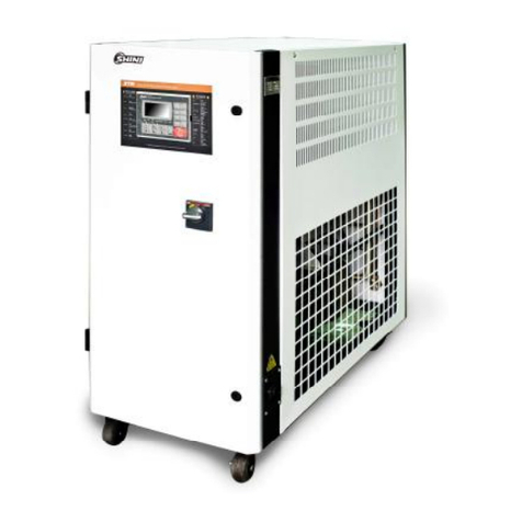
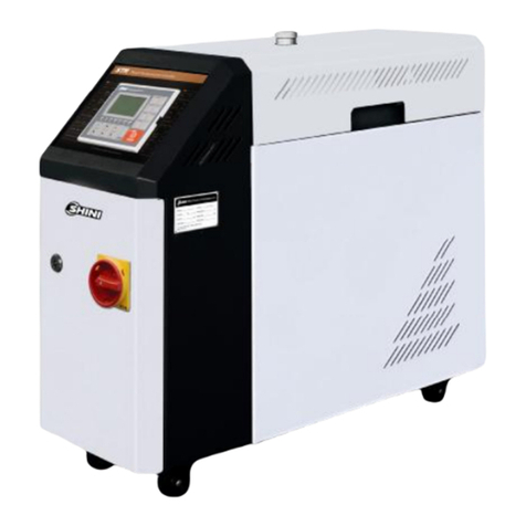
Shini STM-F Series User manual

STM-F
"LargeFlow" Oil Heater
Date:Jul.2014
Version: Ver.B(English)


3(62)
Contents
1. General Description..................................................................................7
1.1 CodingPrinciple...................................................................................8
1.2 Feature.................................................................................................8
1.3 TechnicalSpecifications.....................................................................10
1.3.1 Specification............................................................................10
1.3.2 PumpPerformance..................................................................10
1.3.3 ReferenceFormulaofMouldControllersModelSelection.......11
1.4 SafetyRegulations.............................................................................12
1.4.1 SafetySignsand Labels..........................................................12
1.4.2 Signsand Labels.....................................................................13
1.4.3 OperationRegulations.............................................................14
1.5 ExemptionClause..............................................................................16
2. StructureCharateristics and Working Principle...................................17
2.1 WorkingPrinciple...............................................................................17
2.2 AssemblyDrawing.............................................................................18
2.2.1 AssemblyDrawing(STM-4575F).............................................18
2.2.2 PartsList (STM-4575F)...........................................................19
2.2.3 Heat ExchangerDrawing.........................................................20
2.2.4 WaterInletContectorAssembly..............................................21
2.2.5 Oil pipe frompumpAssembly..................................................22
2.2.6 HeatingHopperAssembly.......................................................23
2.2.7 Oil TankAssembly...................................................................25
2.2.8 Oil DischargeConnectorAssembly.........................................26
2.2.9 WaterDrainageConnector......................................................27
2.3 ElectricalDiagram..............................................................................28
2.3.1 MainCircuit (STM-4575F)(400V)............................................28
2.3.2 ControlCircuit (STM-4575F)(400V)........................................29
2.3.3 ElectricalComponentsLayout (STM-4575F)(400V)...............30
2.3.4 ElectricalComponentsList (STM-4575F)(400V)....................31
2.3.5 MainCircuit (STM-4575F)(230V)............................................32
2.3.6 ControlCircuit (STM-4575F)(230V)........................................33

4(62)
2.3.7 ElectricalComponentsLayout (STM-4575F)(230V)...............34
2.3.8 ElectricalComponentsList (STM-4575F)(230V)....................35
2.4 MainElectricalComponentsDescription............................................36
2.4.1 Overload Relay........................................................................36
3. Installation and Debugging.....................................................................37
3.1 Installation Space...............................................................................37
3.2 Pipeline Connection...........................................................................38
3.3 PowerConnection..............................................................................39
4. Operation Guide......................................................................................40
4.1 ControlPanel.....................................................................................40
4.2 Structureofthe Unit...........................................................................43
4.3 Machine Startup.................................................................................44
4.4 Stop theMachine...............................................................................52
5. Trouble-shooting.....................................................................................53
6. Maintenance and Repair.........................................................................55
6.1 YType StrainerCleaning...................................................................56
6.2 SolenoidValve...................................................................................56
6.3 HeaterPipe Cleaning.........................................................................57
6.4 Printed Circuit Board..........................................................................58
6.5 DisplayTerminalConnectingDiagram...............................................60
6.6 MaintenanceSchedule.......................................................................61
6.6.1 About theMachine...................................................................61
6.6.2 Installation &Inspection...........................................................61
6.6.3 DailyChecking.........................................................................61
6.6.4 WeeklyChecking.....................................................................61
6.6.5 TrimonthlyChecking................................................................61
6.6.6 Half-yearlyChecking................................................................61
6.6.7 YearlyChecking.......................................................................62
6.6.8 3yearChecking.......................................................................62
TableIndex
Table1-1 Specification...................................................................................10

5(62)
Table1-2: StandardWaterQuality...................................................................15
Table2-1 PartsList (STM-4575F)..................................................................19
Table2-3: Heat ExchangerPartsList...............................................................20
Table2-4:WaterInlet ContectorPartsList.......................................................21
Table2-5: Oil pipefrompumppartslist............................................................22
Table2-6: HeatingHopperPartsList................................................................24
Table2-7: Oil tankPartsList............................................................................25
Table2-8: Oil DischargeConnectorPartsList..................................................26
Table2-9:WaterDrainageConnectorPartsList..............................................27
Table2-10:PartsList(STM-4575F)(400V)......................................................31
Table2-11:PartsList(STM-4575F)(230V)......................................................35
Table4-1: ControlPanel...................................................................................40
Table:4-2: ErrorType........................................................................................42
PictureIndex
Picture1-1 PumpPerformance......................................................................10
Picture2-1 WorkingPrinciple.........................................................................17
Picture2-2 AssemblyDrawing(STM-4575F).................................................18
Picture2-3 HeatExchangerDrawing.............................................................20
Picture2-4 WaterInlet ContectorAssembly..................................................21
Picture2-5 Oil pipefrompumpAssembly......................................................22
Picture2-6 HeatingHopperAssembly...........................................................23
Picture2-7 Oil tankdrawing...........................................................................25
Picture2-8 Oil DischargeConnectorAssembly.............................................26
Picture2-9 Waterdrainageconnectordrawing..............................................27
Picture2-10 MainCircuit................................................................................28
Picture2-11 ControlCircuit (STM-4575F)(400V)..........................................29
Picture2-12 ElectricalComponentsLayout (STM-4575F)(400V).................30
Picture2-13 MainCircuit (STM-4575F)(230V)..............................................32
Picture2-14 ControlCircuit (STM-4575F)(230V)...........................................33
Picture2-15 ElectricalComponentsLayout (STM-4575)(230V)...................34
Picture2-16 OverloadRelay..........................................................................36
Picture3-1 InstallationSpace........................................................................37

6(62)
Picture3-2 Ball Valve.....................................................................................38
Picture3-3 PipelineConnection.....................................................................38
Picture4-1 ControlPanel...............................................................................40
Picture4-2 Menu Outline...............................................................................43
Picture4-3 MainPowerSwitch......................................................................44
Picture4-4 InitialMenu..................................................................................44
Picture4-5 ControlSetting.............................................................................45
Picture4-6 AlarmSetting...............................................................................46
Picture4-7 OutputSetting..............................................................................47
Picture4-8 TemperatureSetting....................................................................48
Picture4-9 TimeSetting.................................................................................49
Picture4-10 CommunicationSetting..............................................................50
Picture4-11 Equipment Setting......................................................................51
Picture4-12 OperationScreen.......................................................................52
Picture6-1 Y Type Strainer............................................................................56
Picture6-2 SolenoidValve.............................................................................56
Picture6-3 HeaterPipe 1...............................................................................57
Picture6-4 HeaterPipe 2...............................................................................57

7(62)
1.General Description
Read thismanualcarefullybeforeoperationtopreventdamageofthe
machine orpersonalinjuries.
STM-Fseries''LargeFlow'' oil heatermainlyappliedinextruderand rubber
injection moldingorotheroccasion requireslargeflow, strongcooling capability.
Besides,itsalsoapplicabletothe fieldswithsamerequirements.Thisseriesof
heatersadoptindirectcoolingmethodafterreturnoil fromthe mouldpassed
throughthe cooler.Theoil pressurized bypump,throughheaterpipeit will be
heated,then it returnstothemouldtoreachthe requirementofheatingand
maintainingconstant temperature.AdoptsP.I.Dtemperaturecontrollercan ensure
stabletemperaturecontrol.
Model: STM-4575F

8(62)
1.1CodingPrinciple
STM –xxxx F
Oil “LargeFlow”
First TwoCodes: HeaterPower(kW)
LastTwoCodes: PumpPower(×10-1HP)
ShiniMoldTemp. Controller
1.2Feature
StandardConfiguration
1)It seasyfordismantlement and maintenance.
2)P.I.D.full-digitaltemperaturecontrolsystemcanreachmaximumtemperature
at 200 andmaintainamouldtemperaturewithaccuracyof ±0.5 at any
status.
3)Controlleradopts3.2" LCD foreasyoperation.
4)It equippedwithlarge-flowpumpwhichespeciallysuitableformouldsrequiring
large-flowheatingmediumtomaintainconstant temperatureinplastics
moldingoccasions.
5)Cooleradoptedplateheat exchangerhasoptimalexchangingeffect whichcan
reachthe highest coolingabilityto40kWand lowertemperaturequickly.
6)Powerphasereversealarm,pumpoverload alarm,over-temperaturealarm,
lowlevelsensoralarmandothersafetydevicescan self-detectmachines
abnormalityanddisplaythe abnormalsituations.
Accessoryoption
1)Watermanifolds,TeflonhoseandTransferoil areoptional.
2)RS485communication functionisoptional.
3)Displayofmouldtemperatureandmouldreturnoil temperatureisoptional.
4)Whenmachine stops, returnoil reversefunction isoptional.

9(62)
All serviceworkshouldbe carried out byaperson withtechnicaltrainingor
correspondingprofessionalexperience.The manualcontainsinstructionsforboth
handlingand servicing.Chapter6, whichcontainsserviceinstructionsintendedfor
serviceengineers. Otherchapterscontaininstructionsforthedailyoperator.
Anymodificationsofthemachinemustbe approved bySHINI inordertoavoid
personalinjuryand damagetomachine.Weshall not beliableforanydamage
causedbyunauthorized changeof themachine.
Ourcompanyprovidesexcellent after-salesservice. Shouldyou haveanyproblem
duringusingthemachine,pleasecontactthecompanyorthelocalvendor.
HeadquarterandTaipeifactory China ServiceLine:
Tel:(886)226809119Tel:800999 3222

10(62)
1.3TechnicalSpecifications
1.3.1Specification
Table1-1 Specification
Model
Heater
Power
(kW)
Pump
power
(HP)
Max.
pump
Flow
(L / min)
Max.
pump
pressure
(bar)
Heating
Tank
Number
Main/
Sub.
OilTank
(L)
Cooling
Method
Mould
Coupling*
(inch)
Inlet/Outle
t
(inch)
Cooling
Water
Inlet/Out
let
(inch)
Dimensions
(mm)
(H×W×D)
Weight
(kg)
STM-4575F
45 7.5 424 3.0 3 16 /51
Indirect
17
8”-12(1x2)
1.5”/
1.5”13 /13
1200x500x
1350 270
Note: 1)"*"Standsfor options.Wereservethe right tochange
2) Pumptestingstandard: Power of 50 Hz,specificationswithout prior notice
purified water at20℃. (Thereis ±10%tolerance
for eithermax. flowrateor max. pressure).
3) Power supply: 3Φ,400VAC,50 Hz
1.3.2PumpPerformance
Picture1-1 PumpPerformance

11(62)
1.3.3ReferenceFormulaofMouldControllersModelSelection
HeaterPower(kW)=mouldweight (kg) ×mouldspecificheat (kcal/kg) ×
temperaturedifferencebetween mouldandenvironment() ×safetycoefficient
/ heatingduration / 860
Note: safetycoefficientcan selectavalue from1.3to1.5.
FlowRate(L/min)=heaterpower(kw) ×860 / [heatingmediumspecific
(kcal/kg) ×heatingmediumdensity(kg/L)×in/outlettemperaturedifference
()×time(60)]
Note Waterspecificheat=1kcal/kg
Heatingmediumoil specificheat =0.49kcal/kg
Waterdensity=1kg/L
Heatingmediumoil density=0.842kg/L

12(62)
1.4 SafetyRegulations
Strictlyabide bythe followingsafetyregulationstoprevent damageofthe
machine orpersonalinjuries.
1.4.1SafetySignsand Labels
Danger!
Theunit isdesigned toendurehightemp,andhighpressure. Forsafe
operation,do notremovethe coversorswitches.
Attention!
Theunit shouldbe operated byqualifiedpersonnelonly.
Duringoperation, avoidwearingglovesorclothesthat maycausedanger.
Turnoff mainswitchwhen powersupplyisoff.
Stop the unitwhen theremaybe powersupplyproblemscausedbystatic
electricity.
Put onsafetyglovesand shoesduringinstallation orrelocation.
Componentsfromourcompanycan onlybe used forreplacement.
Warning!
Donottouchthe switchwithwet object orhands.
Donotusethemachinebeforefullyawareofitsperformance.
Becarefulnot totouchorhit the switchorsensor.
Pleaseput spareemergencyswitchinsuitableplaceand rememberthe location.
Pleasekeepenoughoperationspace,andkeep awayobstacles.
Toavoidproducingstatics, cleanthefloorfromoil orwatertokeep adry
environment.
Protectthemachineagainst severevibration orcollision.
Don t takeoffordirtysafetysignsprivately. Drunken,medicine-taking, or
menwithout properjudgementshouldnotoperatethemachine.
Warning!
All screwsofelectriccomponentsincabinet havebeen tightenedand no
needforperiodicalchecking.

13(62)
1.4.2Signsand Labels
Pleaseaccordingtoscheduletomake
regularmaintenance.
(Attached onmotor cover)
Thisistoindicatemotorrotating
direction.
When phasereversalhappens, thealarm
soundsandindicatoroncontrolpanelwill
indicate.Pleaseexchangethe placeof
twooftheelectricalwirestosolvethis
problem.
Highvoltage! Electricalshock may
happen.Carefulness isrequired fromthe
operator.
Attentions!
Thisisgeneralwarningswhichoperators
shouldpayattentionto.
Oil dischargevalve: oildischargeport
when machine ischangingoil.
Highoil level: max. oil levelofmachine in
constant temperature.

14(62)
Frommould: connectorforcirculating
water/oil of comingfrommould
Pumppressuremeter:indicatingactual
pressureofsystem.
Tomold:connectorforcirculatingwater/
oil togotomould.
Oil inlet: Machine oil inlet
1.Tomaintaintemperaturestability,
coolingwaterpressuremustbehigher
than2baratall time,but shouldnever
exceed 5barinanycase.
2.Clean Y-shape CoolingWaterStrainer
periodicallytoensureperfectcooling
capacity.
Wateroutlet: coolingwateroutlet
Waterinlet: coolingwaterintlet
1.4.3OperationRegulations
1)Whencoolingwater: qualifiedstandardcoolerforindustrialuseis
recommented. ReferenceasTable1-2.
2)When inuse,iftherespoorwaterdrainage orpoorcontroleffect,clean up the
solenoidvalveat onceorcheckcoolingwateroutlet hasblockageornot.
3)Donotmovetheunit when it isinoperation.
4)Duringrepairing, wait until oil temperaturefallsbelow30 .
5)STM-Fpossessespumpoverload device.When overloadoccurs,pumpand

15(62)
heaterwill stop working. At thismoment, itneedstocheck overload reasons
(phaseshortage,pipe obstruction,broken bearing,etc.)Afterthe systemruns
normally, press RESETon overloadrelaytorest theoperation.
6)Beforeturnoff thepump, wait until oil temperaturefallsblow50℃.Orthe
servicelifeof theunitwouldbe affected.
Table1-2: StandardWaterQuality
Cooling Water
No.
Control Items Direct Cooling Water
CirculatingCooling
Water
SystemReplenishment
Water
1 pH 6.0-9.0 6.5-8.5
2 SS(mg/L)≤30 -
3 Turbidity(NTU)≤ - 3
4 BOD5(mg/L)≤ 30 10
5 CODcr≤(mg/L)- 50
6 Fe(mg/L)≤ - 0.3
7 Mn(mg/L)≤ - 0.1
8 Cl(mg/L)≤ 250 250
9 GH(CaCO3/mg/L)≤ 450 450
10 Total ALK (CaCO3/mg/L)≤ 500 350
11 Sulfate(mg/L)≤ 600 250
12 NH3-N(mg/L)≤ - 10
13 Total P(Pmg/L)≤ - 1
14 TDS(mg/L)≤ 1000 1000
15 Fecalcoliform(/L)≤ 2000 2000
16 Petroleum(mg/L)≤ - 1
17 Anionicsurfactant(mg/L)≤ - 0.5

16(62)
1.5ExemptionClause
Thefollowingstatementsclarifytheresponsibilitiesandregulationsbornbyany
buyeroruserwho purchasesproductsandaccessoriesfromShini(including
employeesandagents).
Shiniisexempted fromliabilityforanycosts,fees,claimsandlossescausedby
reasonsbelow:
1.Beforeuseofthemachine,carelessorman-madeinstallations,operationand
maintenancesupon machinewithout referringtotheManual.
2. Anyincidentsbeyondhumanreasonablecontrols, whichincludeman-made
viciousordeliberatedamagesorabnormalpower,and machinefaultscaused
byirresistiblenaturaldisastersincludingfire,flood,stormand earthquake.
3. Anyoperationalactionsthatarenotauthorized byShiniuponmachine,
includingaddingorreplacingaccessories, dismantling,deliveringorrepairing.
4. Useconsumablesoroil mediathatarenotappointedbyShini.

17(62)
2. Structure Charateristics andWorkingPrinciple
2.1WorkingPrinciple
Picture2-1 WorkingPrinciple
Thehightemperatureoil returnstothe machine and thenbepressured by
pumptotheheaters. Afterbeingheated, oil will be forcedtothemouldand
continue the circle.Inthe process, iftheoil temperatureistoohigh,systemwill
activatethesolenoidvalvetolet coolingwatercooldownhightemperatureoil
indirectlyuntil thetemperatureisdowntothe systemrequirement. Ifthe
temperaturekeepsincreasingandreachestothe set pointofEGO, the system
will sound alarmandstop operation.The systemwill havelowlevelalarmand
stop workingifoil levelfallsdownbelowthe set point.

18(62)
2.2AssemblyDrawing
2.2.1AssemblyDrawing(STM-4575F)
Remarks: Pleaserefer tomateriallist 2.2.2for specificexplanationofthe Arabicnumbersin
partsdrawing.
Picture2-2 AssemblyDrawing(STM-4575F)

19(62)
2.2.2PartsList (STM-4575F)
Table2-1 PartsList (STM-4575F)
Part No.
No. NameSTM-4575F
1 Movable castor3"*YW03000300200
2 Long doorlockYW00000000100
3 Breakerinterlock*YE41161500000
4 Big hinge-left CL203-1 YW06203100400
5 Controller MT100-01* YE81100010000
6 Oil inlet pipe of plateheat exchangerSTM-4575F-ALL-16
7 Castor withbrake3" YW03000300000
8 Water inlet connectorassembly STM-4575F-F-ALL
9 oil pipe frompumpassemblySTM-4575F-B-ALL
10 Oil outlet pipeof plateheat exchangerSTM-4575F-ALL-15
11 HeatingtankassemblySTM-4575F-A-ALL
12 H transfer toPTconnectorSTM-607-ALL-07/01
13 LOK-fitting6mm*1/4"PT YW05061400000
14 Pressuregauge(0~1.0MPa)* YW85001000100
15 Aluminiumoil cap 3/4"PTBH12030403040
16 Oil tankassemblySTM-4575F-C-ALL
17 EGO assembly** BH90115000050
18 Heat exchangerassemblySTM-4575F-D-ALL
19 PumpYS-35F low(YUANXIN 5.5kw) *YM20153500000
20 Liquid level indicatorassembly*BH12060700210
21 Oil discharge connector assembly*STM-4575F-G-ALL
22 Water drainage connector assembly*STM-4575F-E-ALL
*means possiblebrokenparts.
** means easybroken part. and sparebackup issuggested.
Please confirm the versionofmanual beforeplacingthe purchase ordertoguaranteethat
the itemnumber ofthe sparepart isinaccordancewiththe realobject.

20(62)
2.2.3Heat ExchangerDrawing
Picture2-3 HeatExchangerDrawing
Table2-3: Heat ExchangerPartsList
No. NamePart No.
1 Tonflon tube connector 1/2"PT×1/2"H(L) YW04121200000
2 Plateheatexchanger (BL20-78D) YW87957800000
3 Tonflon tube connector 3/4"PT×3/4"HBH12030400310
4 Copper pipecoupler 3/4"PT×3/4"PTBH12030400010
5 Solenoid valve3/4"(KL5231020S) *YE32312200000
*means possiblebrokenparts.
** means easybroken part. and sparebackup issuggested.
Please confirmthe versionofmanualbeforeplacingthe purchase order toguaranteethat
the itemnumber ofthe sparepart isinaccordancewiththe realobject.
Other manuals for STM-F Series
1
This manual suits for next models
2
Table of contents
Other Shini Heater manuals
Popular Heater manuals by other brands

Thermoscreens
Thermoscreens CS 1000 Installation, operation and maintenance instructions

THERMOFAN
THERMOFAN TF2400S installation guide

Leister
Leister LE 3000 operating instructions

AUROOM
AUROOM Aura 4,5 kW Installation and instruction manual

Klarstein
Klarstein Baltrum manual

Saunum
Saunum Spa Session Instructions for use and installation