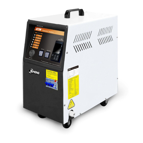
Shini STM-F Series User manual

STM-F
"LargeFlow" Oil Heater
Date:Feb.2019
Version:Ver.D(English)


3(43)
Contents
1. General Description..................................................................................... 7
1.1 CodingPrinciple......................................................................................8
1.2 Feature....................................................................................................8
1.3 Options....................................................................................................8
1.4 TechnicalSpecifications........................................................................ 10
1.4.1 Specification............................................................................... 10
1.4.2 PumpPerformance..................................................................... 11
1.4.3 ReferenceFormulaofMouldControllersModelSelection.......... 11
1.5 SafetyRegulations................................................................................ 12
1.5.1 SafetySignsand Labels............................................................. 12
1.5.2 Signsand Labels........................................................................ 13
1.5.3 OperationRegulations................................................................ 14
1.6 ExemptionClause................................................................................. 15
2. StructureCharateristics and Working Principle...................................... 16
2.1 WorkingPrinciple.................................................................................. 16
3. Installation and Debugging........................................................................ 17
3.1 Installation Space.................................................................................. 17
3.2 Pipeline Connection.............................................................................. 18
3.3 PowerConnection................................................................................. 18
4. Operation Guide......................................................................................... 19
4.1 ControlPanel........................................................................................ 19
4.2 Menu Introduction................................................................................. 22
4.3 Machine Startup.................................................................................... 23
4.4 Howtochangethe temperature............................................................ 23
4.5 Parametersetting.................................................................................. 24
4.6 Stop theMachine .................................................................................. 32
5. Trouble-shooting ........................................................................................ 34
6. Maintenance and Repair............................................................................ 36
6.1 YType StrainerCleaning...................................................................... 37

4(43)
6.2 SolenoidValve...................................................................................... 37
6.3 HeaterPipe Cleaning............................................................................ 38
6.4 Printed Circuit Board............................................................................. 39
6.5 DisplayTerminalConnectingDiagram.................................................. 41
6.6 MaintenanceSchedule.......................................................................... 42
6.6.1 About theMachine...................................................................... 42
6.6.2 Installation &Inspection.............................................................. 42
6.6.3 DailyChecking............................................................................ 42
6.6.4 WeeklyChecking........................................................................ 42
6.6.5 TrimonthlyChecking................................................................... 42
6.6.6 Half-yearlyChecking................................................................... 42
6.6.7 YearlyChecking.......................................................................... 43
6.6.8 3yearChecking.......................................................................... 43
TableIndex
Table1-1: Specification.................................................................................... 10
Table1-2: StandardWaterQuality................................................................... 15
PictureIndex
Picture1-1: PumpPerformance....................................................................... 11
Picture2-1:WorkingPrinciple.......................................................................... 16
Picture3-1: Installation Space.......................................................................... 17
Picture3-2: Ball Valve...................................................................................... 18
Picture3-3: Pipeline Connection...................................................................... 18
Picture4-1: ControlPanel................................................................................. 19
Pictute4-2: Menu Outline................................................................................. 22
Picture4-3: MainPowerSwitch........................................................................ 23
Picture4-4: InitialMenu.................................................................................... 23
Picture4-5: OperationScreen.......................................................................... 24
Picture4-6: ControlSettingScreen.................................................................. 24

5(43)
Picture4-7: AlarmSettingScreen..................................................................... 25
Picture4-8: Output SettingScreen................................................................... 26
Picture4-9:TemperatureSettingScreen......................................................... 28
Picture6-1: YType Strainer............................................................................. 37
Picture6-2: SolenoidValve.............................................................................. 37
Picture6-3: HeaterPipe1................................................................................ 38
Picture6-4: HeaterPipe2................................................................................ 38

6(43)

7(43)
1.General Description
Readthismanualcarefullybeforeoperation topreventdamageofthe
machine orpersonalinjuries.
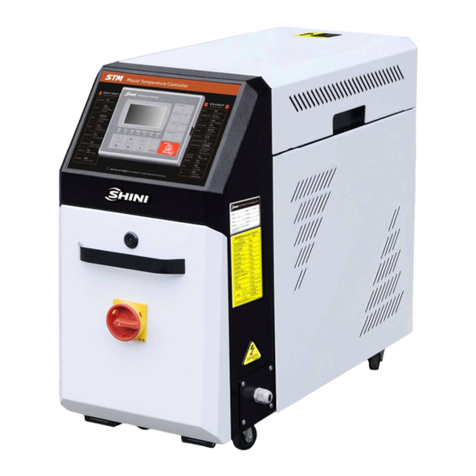
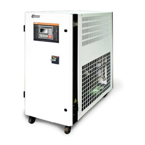
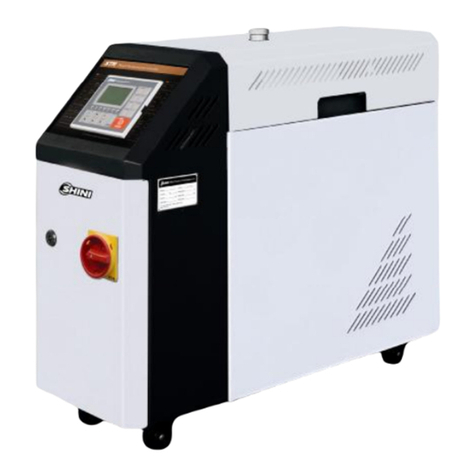
STM-Fseries''Large Flow'' oil heatermainlyappliedinextruderandrubber
injectionmoldingorotheroccasionrequireslargeflow,strongcoolingcapability.
Besides,it salsoapplicabletothefieldswithsamerequirements.Thisseriesof
heatersadoptindirectcoolingmethodafterreturnoil fromthe mouldpassed
throughthecooler.Theoil pressurized bypump,throughheaterpipe itwill be
heated,thenitreturnstothemouldtoreachthe requirementofheatingand
maintainingconstanttemperature.AdoptsP.I.Dtemperaturecontrollercanensure
stabletemperaturecontrol.
Model: STM-4575FModel: STM-3050F

8(43)
1.1CodingPrinciple
STM –xxxx F
Oil “LargeFlow”
First TwoCodes: HeaterPower(kW)
LastTwoCodes: PumpPower(×10-1HP)
ShiniMoldTemp. Controller
1.2Feature
lP.I.D.multi-stagetemperaturecontrolsystemcanmaintainamould
temperature.
lMaximumworkingtemperaturecanreach200 withcontrolaccuracyof
±1.
lControlleradopts3.2" LCD foreasyoperation.
lMultiplesafetydevicesincludingpowerreversephaseprotection,pump
overload protection, overheatprotectionandlowlevelprotection thatcan
automaticallydetectabnormaloperationandindicatethisviavisiblealarm.
lAdoptslarge-flowpumpwithhighstability,whichisnotonlysuitablefor
heatingup mouldsand maintainingtemperature,butalsoforextrusion
moldingand applicationsalike.
lDouble-coolerdesignensuresoptimalcooling effect.
lRS485 communication function isstandard
1.3Options
lWatermanifolds,Teflonhoseand Transferoil areoptional.
lDisplayofmouldtemperatureandmouldreturnoil temperatureisoptional.

9(43)
All serviceworkshouldbe carried out byaperson withtechnicaltrainingor
correspondingprofessionalexperience.The manualcontainsinstructionsforboth
handlingand servicing.Chapter6, whichcontainsserviceinstructionsintendedfor
serviceengineers. Otherchapterscontaininstructionsforthedailyoperator.
Anymodificationsofthemachinemustbe approved bySHINI inordertoavoid
personalinjuryand damagetomachine.Weshall not beliableforanydamage
causedbyunauthorized changeof themachine.
Ourcompanyprovidesexcellent after-salesservice. Shouldyou haveanyproblem
duringusingthemachine,pleasecontactthecompanyorthelocalvendor.
HeadquarterandTaipeifactory China ServiceLine:
Tel:(886)226809119Tel:800999 3222

10(43)
1.4TechnicalSpecifications
1.4.1Specification
Table1-1: Specification
Model STM-3050F STM-4575F
Ver. C D
Maxtemp.(℃) 200 200
Heater Power (kW) 30 45
Pumppower (HP) 5.0 7.5
Max. pumpFlow(L/min) 263 373
Max. pumppressure(bar) 3.0 3.8
HeatingTankNumber 2 33
Main / Sub.Oil Tank(L) 100/18 14/51
CoolingMethod Indirec Indirec
Inlet/Outlet (inch) 1.5”/ 1.5”1.5”/ 1.5”
Dimensions(mm)(H×W×D) 1240×550×1280 1200×500×1350
Weight (kg) 280 270
Note: 1)"*"Standsfor options.Wereservethe right tochange
2) Pumptestingstandard:Power of 50 Hz,specificationswithout prior notice
purified water at20. (Thereis ±10%tolerance
foreithermax. flowrateormax.
pressure).
3) Power supply: 3Φ,400VAC, 50 Hz

11(43)
1.4.2PumpPerformance
Picture1-1: PumpPerformance
1.4.3ReferenceFormulaofMouldControllersModelSelection
HeaterPower(kW)=mouldweight (kg) ×mouldspecificheat (kcal/kg) ×
temperaturedifferencebetween mouldandenvironment() ×safetycoefficient
/ heatingduration / 860
Note: safetycoefficientcan selectavalue from1.3to1.5.
FlowRate(L/min)=heaterpower(kw) ×860 / [heatingmediumspecific
(kcal/kg) ×heatingmediumdensity(kg/L)×in/outlettemperaturedifference
()×time(60)]
Note Waterspecificheat=1kcal/kg
Heatingmediumoil specificheat =0.49kcal/kg
Waterdensity=1kg/L
Heatingmediumoil density=0.842kg/L

12(43)
1.5 SafetyRegulations
Strictlyabide bythe followingsafetyregulationstoprevent damageofthe
machine orpersonalinjuries.
1.5.1SafetySignsand Labels
Danger!
Theunit isdesigned toendurehightemp,andhighpressure. Forsafe
operation,do notremovethe coversorswitches.
Attention!
Theunit shouldbe operated byqualifiedpersonnelonly.
Duringoperation, avoidwearingglovesorclothesthat maycausedanger.
Turnoff mainswitchwhen powersupplyisoff.
Stop the unitwhen theremaybe powersupplyproblemscausedbystatic
electricity.
Put onsafetyglovesand shoesduringinstallation orrelocation.
Componentsfromourcompanycan onlybe used forreplacement.
Warning!
Donottouchthe switchwithwet object orhands.
Donotusethemachinebeforefullyawareofitsperformance.
Be carefulnot totouchorhit the switchorsensor.
Pleaseput spareemergencyswitchinsuitableplaceand rememberthe location.
Pleasekeepenoughoperationspace,andkeep awayobstacles.
Toavoidproducingstatics, cleanthefloorfromoil orwatertokeep adry
environment.
Protectthemachineagainst severevibration orcollision.
Don t takeoffordirtysafetysignsprivately. Drunken,medicine-taking, or
menwithout properjudgementshouldnotoperatethemachine.
Warning!
All screwsofelectriccomponentsincabinet havebeen tightenedand no
needforperiodicalchecking.

13(43)
1.5.2Signsand Labels
Pleaseaccordingtoscheduletomake
regularmaintenance.
Oil dischargevalve: oildischargeport
when machine ischangingoil.
Highoil level: max. oil levelofmachine in
constant temperature.
Frommould: connectorforcirculating
water/oil of comingfrommould
Pumppressuremeter:indicatingactual
pressureofsystem.
Tomold:connectorforcirculatingwater/
oil togotomould.
Oil inlet: Machine oil inlet

14(43)
1.Tomaintaintemperaturestability,
coolingwaterpressuremustbehigher
than2baratall time,but shouldnever
exceed 5barinanycase.
2.Clean Y-shape CoolingWaterStrainer
periodicallytoensureperfectcooling
capacity.
Wateroutlet: coolingwateroutlet
Waterinlet: coolingwaterintlet
1.5.3OperationRegulations
1)When coolingwater: qualified standardcoolerforindustrialuseis
recommented. ReferenceasTable1-2.
2)When inuse, ifthere spoorwaterdrainageorpoorcontroleffect, cleanup
the solenoidvalveat onceorcheck cooling wateroutlet hasblockageornot.
3)Donotmovethe unit when itisinoperation.
4)Duringrepairing, wait until oil temperaturefallsbelow30 .
5)STM-Fpossessespumpoverload device.When overload occurs, pump
and heaterwill stop working.At thismoment,it needstocheck overload
reasons(phaseshortage, pipe obstruction,broken bearing,etc.)Afterthe
systemrunsnormally, press RESETon overload relaytorest the
operation.
6)Beforeturnoffthe pump, wait until oil temperaturefallsblow50 . Orthe
servicelifeof theunitwouldbe affected.

15(43)
Table1-2: StandardWaterQuality
No.
Control Items
Cooling Water
Direct Cooling
Water
Circulating Cooling Water
System Replenishment Water
1 pH 6.0-9.0 6.5-8.5
2 SS(mg/L)≤30 -
3 Turbidity(NTU)≤- 3
4 BOD5(mg/L)≤30 10
5 CODcr≤(mg/L)- 50
6 Fe(mg/L)≤- 0.3
7 Mn(mg/L)≤- 0.1
8 Cl(mg/L)≤250 250
9 GH(CaCO3/mg/L)≤450 450
10 Total ALK (CaCO3/mg/L)≤500 350
11 Sulfate(mg/L)≤600 250
12 NH3-N(mg/L)≤- 10
13 Total P(Pmg/L)≤- 1
14 TDS(mg/L)≤1000 1000
15 Fecalcoliform(/L)≤2000 2000
16 Petroleum(mg/L)≤- 1
17 Anionicsurfactant(mg/L)≤- 0.5
1.6ExemptionClause
Thefollowingstatementsclarifytheresponsibilitiesandregulationsbornbyany
buyeroruserwho purchasesproductsandaccessoriesfromShini(including
employeesandagents).
Shiniisexempted fromliabilityforanycosts,fees,claimsandlossescausedby
reasonsbelow:
1.Beforeuseofthemachine,carelessorman-madeinstallations,operationand
maintenancesupon machinewithout referringtotheManual.
2. Anyincidentsbeyondhumanreasonablecontrols, whichincludeman-made
viciousordeliberatedamagesorabnormalpower,and machinefaultscaused
byirresistiblenaturaldisastersincludingfire,flood,stormand earthquake.
3. Anyoperationalactionsthatarenotauthorized byShiniuponmachine,
includingaddingorreplacingaccessories, dismantling,deliveringorrepairing.
4. Useconsumablesoroil mediathatarenotappointedbyShini.

16(43)
2.Structure Charateristics and Working Principle
2.1WorkingPrinciple
Picture2-1:WorkingPrinciple
Thehightemperatureoil returnstothe machine and thenbepressured bypump
totheheaters.Afterbeingheated, oil will be forced tothe mouldandcontinuethe
circle.Intheprocess,iftheoil temperatureistoohigh,systemwillactivatethe
solenoidvalvetoletcoolingwatercooldownhightemperatureoilindirectlyuntil
thetemperatureisdowntothesystemrequirement.Ifthetemperaturekeeps
increasingandreachestothesetpointofEGO, the systemwill soundalarm and
stop operation.Thesystemwill havelowlevelalarm and stopworkingifoil level
fallsdownbelowtheset point.

17(43)
3.Installationand Debugging
3.1InstallationSpace
Duringinstallation of themachine,keep atleast500mminstallation spacearound
the machineasfollowingpicture. Don t installthemachineinanarroworcrowded
placewithotherobjects.Thiswouldcauseinconveniencetooperation,
maintenanceandrepair.
Keepawayinflammablesandexplosivegoods.
Picture3-1: Installation Space

18(43)
3.2Pipeline Connection
1)Opentheball valvewhen machine isfillingtheoil.Afterthe mouldisfilled
withoil, closethevalveandstart upthemachine.
Picture3-2: Ball Valve
2)Afterconnectthecoolingwateroutlet todrainageport, turnon thewater
sourceswitch.
Attention:Cooling waterdischargeportisshownasbelow.
Reverseconnection isforbidden.
Picture3-3: Pipeline Connection
3.3Power Connection
Makesurethepowermatchthespecification, thenconnect the powersupply.
Pleasecheck thevoltagespecificationsignson machine snameplatecarefully.
Thepowersupplymustmatchthespecificationindicatedonnameplate.Thecable
mustmatchthesectionspecification indicatedincircuit diagram.

19(43)
4.Operation Guide
4.1 Control Panel
Picture4-1: ControlPanel
Table4-1: ControlPanel
No. Name Functions Remarks
Heating(Main) Heatingoutputindicator -
Heating(SUB) Auxiliaryheatingoutputindicator -
Cooling Coolingindicator -
Pumprotating
Displaypumppositive
action indicator
-
Pumprotating
directionreverse
Pumpreverseaction indicator-
Watersupply Water refillingindicator -
Alarm Send alarmindicatorRefer totable4-2for
errorsinstruction.
ON/OFF
ON/OFF Run/stop key-

20(43)
No. Name Functions Remarks
Auto-tuning Autotuningkey-
Reverse/Drain Reverserunning/discharge -
Mandatorycooling Forcedcooling key
Hold thebutton for 2secs
toenableforcecooling.It
stop heating whileenable
100% cooling. It stops
after the temperutredrops
belowCooling Temp.
Buzzer Buzzer off switch
After press”BUZZER”
button, ”BUZZER”LED
on,
Buzzer and alarmrelayin
idle modeeven error
occurs.
Timer Reserved timing key-
Reverse Reversekey-
Backup Backup key-
Power ON/OFF Power on/off key-
Menu Menu keyParameter confirmation
Confirmparameter Confirmkey-
Set valve
modification
Settingkey-
- Upkey-
- Downkey-
- Left key-
- Rightkey-
Other manuals for STM-F Series
1
This manual suits for next models
2
Table of contents
Other Shini Heater manuals
Popular Heater manuals by other brands

Stelpro
Stelpro ARWF1001 user manual

2VV
2VV ESSENSSE NEO VCES2-B...E3 Series installation manual

Polar Electro
Polar Electro Polar Heat C1 user manual

Zibro
Zibro R 421 E operating manual

Pinnacle Climate
Pinnacle Climate MH-150T-DFV-A User's manual and operating instructions

Stelpro
Stelpro AALUX3 Series user guide

Taurus
Taurus ALPATEC TROPICANO S2001 manual

Master
Master CF 75 User and Maintenance Book

Climate King
Climate King HCK-BX5 User's manual and operating instructions

Twin-Star International
Twin-Star International SH-106 manual

Scarlett
Scarlett SC-2158 instruction manual

Black & Decker
Black & Decker BDH-D16 manual