Shop fox M1112 User manual

MODEL M1112 12" X 36"
GUNSMITHING LATHE
Phone: (360) 734-3482 • Online Technical Support: [email protected]
COPYRIGHT © NOVEMBER 2007 BY WOODSTOCK INTERNATIONAL, INC. REVISED APRIL 2008.
WARNING: NO PORTION OF THIS MANUAL MAY BE REPRODUCED IN ANY SHAPE OR FORM WITHOUT
THE WRITTEN APPROVAL OF WOODSTOCK INTERNATIONAL, INC. Printed in China
#10091CR
OWNER'S MANUAL

K_`jdXelXcgifm`[\jZi`k`ZXcjX]\kp`ejkilZk`fejfek_\gifg\ij\klg#
fg\iXk`fe#dX`ek\eXeZ\Xe[j\im`Z\f]k_`jdXZ_`e\&\hl`gd\ek%
=X`cli\kfi\X[#le[\ijkXe[Xe[]fccfnk_\`ejkilZk`fej^`m\e`ek_`j
dXelXcdXpi\jlck`ej\i`fljg\ijfeXc`ealip#`eZcl[`e^XdglkXk`fe#
\c\ZkifZlk`fefi[\Xk_%
K_\fne\if]k_`jdXZ_`e\&\hl`gd\ek`jjfc\cpi\jgfej`Yc\]fi`kjjX]\
lj\%K_`ji\jgfej`Y`c`kp`eZcl[\jYlk`jefkc`d`k\[kfgifg\i`ejkXccX$
k`fe`eXjX]\\em`ifed\ek#g\ijfee\ckiX`e`e^Xe[ljX^\Xlk_fi`qX$
k`fe#gifg\i`ejg\Zk`feXe[dX`ek\eXeZ\#dXelXcXmX`cXY`c`kpXe[
Zfdgi\_\ej`fe#Xggc`ZXk`fef]jX]\kp[\m`Z\j#YcX[\&Zlkk\i`ek\^i`kp#
Xe[k_\ljX^\f]g\ijfeXcgifk\Zk`m\\hl`gd\ek%
K_\dXel]XZkli\in`ccefkY\_\c[c`XYc\]fi`ealipfigifg\ikp
[XdX^\]ifde\^c`^\eZ\#`dgifg\ikiX`e`e^#dXZ_`e\df[`]`ZXk`fejfi
d`jlj\%
Jfd\[ljkZi\Xk\[Ypgfn\ijXe[`e^#jXn`e^#^i`e[`e^#[i`cc`e^#Xe[
fk_\iZfejkilZk`feXZk`m`k`\jZfekX`ejZ_\d`ZXcjbefnekfk_\JkXk\f]
:Xc`]fie`XkfZXlj\ZXeZ\i#Y`ik_[\]\Zkjfifk_\ii\gif[lZk`m\_Xid%
Jfd\\oXdgc\jf]k_\j\Z_\d`ZXcjXi\1
C\X[]ifdc\X[$YXj\[gX`ekj%
:ipjkXcc`e\j`c`ZX]ifdYi`Zbj#Z\d\ekXe[fk_\idXjfeipgif[lZkj%
8ij\e`ZXe[Z_ifd`ld]ifdZ_\d`ZXccp$ki\Xk\[cldY\i%
Pflii`jb]ifdk_\j\\ogfjli\jmXi`\j#[\g\e[`e^fe_fnf]k\epfl
[fk_`jkpg\f]nfib%Kfi\[lZ\pfli\ogfjli\kfk_\j\Z_\d`ZXcj1
Nfib`eXn\ccm\ek`cXk\[Xi\X#Xe[nfibn`k_Xggifm\[jX]\kp\hl`g$
d\ek#jlZ_Xjk_fj\[ljkdXjbjk_XkXi\jg\Z`Xccp[\j`^e\[kf]`ck\i
flkd`ZifjZfg`ZgXik`Zc\j%

SET UPELECTRICAL MAINTENANCE SERVICE PARTS
OPERATIONS
SAFETYINTRODUCTION
USE THE QUICK GUIDE PAGE LABELS TO SEARCH OUT INFORMATION FAST!
Contents
INTRODUCTION ..................................................................................................3
Woodstock Technical Support ............................................................................ 3
Controls and Features ..................................................................................... 6
SAFETY ............................................................................................................7
Standard Safety Instructions ............................................................................. 7
Additional Safety Instructions for Lathes .............................................................. 9
Avoiding Potential Injuries.............................................................................. 10
ELECTRICAL .................................................................................................... 11
220V Operation ........................................................................................... 11
Extension Cords .......................................................................................... 11
Electrical Specifications ................................................................................ 11
SET UP .......................................................................................................... 12
Inventory .................................................................................................. 12
Uncrating and Lifting .................................................................................... 13
Cleaning Machine......................................................................................... 14
Machine Placement ...................................................................................... 14
Mounting to Shop Floor.................................................................................. 15
OPERATIONS ................................................................................................... 20
General .................................................................................................... 20
Spindle Speeds............................................................................................ 20
Swapping Jaws............................................................................................ 24
Four-Jaw Chuck .......................................................................................... 25
Faceplate.................................................................................................. 26
Centers..................................................................................................... 27
Spindle Spider ............................................................................................ 27
Cutting Shallow Tapers with Tailstock ................................................................ 36
Drilling with Tailstock ................................................................................... 36
Gap Piece Removal ...................................................................................... 37
Model M1112 Lathe Accessories........................................................................ 38
MAINTENANCE ................................................................................................. 39
General Maintenance .................................................................................... 39
General Cleaning ......................................................................................... 39
General Lubrication...................................................................................... 39
Coolant System ........................................................................................... 41
Continued on next page

USE THE QUICK GUIDE PAGE LABELS TO SEARCH OUT INFORMATION FAST!
SET UP ELECTRICALMAINTENANCE
SERVICEPARTS OPERATIONS SAFETY INTRODUCTION
SERVICE ......................................................................................................... 42
Half-Nut Adjustment..................................................................................... 45
M1112 Main Electrical Box Wiring Diagram .......................................................... 50
Headstock Shifters and Change Gears ................................................................ 57
PARTS ........................................................................................................... 58
Headstock Gearing and Control Panel ............................................................... 59
Quick Change Gearbox .................................................................................. 61
Apron Assembly........................................................................................... 63
Saddle and Cross Feed .................................................................................. 65
Compound Rest ........................................................................................... 67
Tailstock Assembly ....................................................................................... 68
Bed and Motor Parts ..................................................................................... 69
Cabinet Parts ............................................................................................. 70
Spindle Switch Control Rod Assembly................................................................. 72
Coolant System and Lamp .............................................................................. 73
Lathe Accessories ........................................................................................ 74
Main Electrical Box ...................................................................................... 75
Follow Rest and Steady Rest ........................................................................... 76
Label Placement ......................................................................................... 77

-3-
M1112 12" x 36" Gunsmithing Lathe
INTRODUCTION
Woodstock Technical Support
INTRODUCTION
Your new SHOP FOX®Model M1112 Lathe has been specially designed to provide many years of trouble-
free service. Close attention to detail, ruggedly built parts and a rigid quality control program assure
safe and reliable operation.
Woodstock International, Inc. is committed to customer satisfaction. Our intent with this manual is to
include the basic information for safety, set up, operation, maintenance, and service of this product.
We stand behind our machines! In the event that questions arise about your machine, please contact
Woodstock International Technical Support at (360) 734-3482 or send e-mail to: tech-support@shopfox.
biz. Our knowledgeable staff will help you troubleshoot problems and process warranty claims.
If you need the latest edition of this manual, you can download it from http://www.shopfox.biz.
If you have comments about this manual, please contact us at:
Woodstock International, Inc.
Attn: Technical Documentation Manager
P.O. Box 2309
Bellingham, WA 98227
Email: manuals@woodstockint.com

-4-
M1112 12" x 36" Gunsmithing Lathe
INTRODUCTION
Phone #: (360) 734-3482 • Online Tech Support: tech-support@shopfox.biz • Web: www.shopfox.biz
MACHINE
SPECIFICATIONS
MODEL M1112
12" X 36" GUNSMITHING LATHE
Product Dimensions:
Overall Weight with Stand.............................................................................................. 1213 lbs.
Overall Length/Width/Height with Stand................................................................... 61"x 26"x 541⁄2"
Overall Stand Footprint (Length/Width) .........................................................................141⁄2"x 571⁄2"
Stand Weight.................................................................................................................. 360 lb
Stand Length/Width/Height.............................................................................. 591⁄4"x 193⁄4"x 301⁄2"
Shipping Dimensions:
Crate 1
Type ..................................................................................................................... Wood
Content ..............................................................................................................Machine
Weight................................................................................................................ 959 lbs.
Length/Width/Height...................................................................................... 66"x 30"x 30"
Crate 2
Type ..................................................................................................................... Wood
Content .................................................................................................................. Base
Weight................................................................................................................ 375 lbs.
Length/Width/Height...................................................................................... 31"x 26"x 20"
Electrical:
Switch..............................................................................................................ON/OFF Buttons
Cord Length ..................................................................................................................... 6 ft.
Cord Gauge.................................................................................................................. 14 AWG
Recommended Circuit Size ................................................................................................15 Amp
Plug................................................................................................................................. No
Motors:
Type ..............................................................................................TEFC Capacitor Start Induction
Horsepower ..................................................................................................................... 2 HP
Voltage/Amps............................................................................................................. 220V/10A
Phase........................................................................................................................... Single
Speed ...................................................................................................................... 1725 RPM
Cycle ............................................................................................................................60 Hz
Number Of Speeds ................................................................................................................. 1
Power Transfer ................................................................................................ Belt Drive to Gear
Bearings .................................................................................Shielded and Permanently Lubricated
Main Specifications:
Operation Information
Swing Over Bed ........................................................................................................... 12"
Distance Between Centers .............................................................................................. 36"
Swing Over Cross Slide ................................................................................................... 7"
Swing Over Saddle....................................................................................................1111⁄32"
Swing Over Gap ........................................................................................................... 17"

-5-
M1112 12" x 36" Gunsmithing Lathe
INTRODUCTION
Operation Information (continued)
Maximum Tool Bit Size................................................................................................... 5⁄8"
Compound Travel ........................................................................................................31⁄4"
Carriage Travel............................................................................................................ 29"
Cross Slide Travel........................................................................................................61⁄4"
Headstock Information:
Spindle Bore..............................................................................................................15⁄8"
Spindle Taper.......................................................................................................... MT #5
Number of Spindle Speeds ................................................................................................ 9
Range of Spindle Speeds ...................................... 70, 200, 220, 270, 360, 600, 800, 1000, 1400 RPM
Spindle Type..................................................................................................D1-5 Camlock
Spindle Bearings ........................................................................................... Tapered Roller
Tailstock Information:
Tailstock Travel ............................................................................................................ 4"
Tailstock Taper ........................................................................................................ MT #3
Tailstock Barrel Diameter ............................................................................................. 19⁄16"
Threading Information:
Number of Inch Threads..................................................................................................40
Range of Inch Threads........................................................................................... 4–112 TPI
Number of Metric Threads ...............................................................................................29
Range of Metric Threads ...................................................................................... 0.2–4.5mm
Number of Longitudinal Feeds ..........................................................................................40
Range of Longitudinal Feeds ......................................................................... 0.0011–0.0311 in.
Number of Cross Feeds ...................................................................................................40
Range of Cross Feeds ............................................................................ 0.0004–0.0105 in./rev.
Other Dimensions:
Bed Width.................................................................................................................71⁄4"
Leadscrew TPI.......................................................................................................... 8 TPI
Leadscrew Length ........................................................................................................44"
Leadscrew Diameter ..................................................................................................... 7⁄8"
Feed Rod Diameter..................................................................................................... 25⁄32"
Steady Rest Capacity ................................................................................................ 3⁄16"–2"
Follow Rest Capacity..................................................................................................1⁄4"–1"
Faceplate Size ............................................................................................................10"
Construction Information:
Stand............................................................................................................................................. CastIronandSteel
Headstock......................................................................................................................................................CastIron
HeadstockGears.......................................................................................................... FlameHardenedandGround
Bed............................................................................................................................InductionHardenedandGround
Body...............................................................................................................................................................CastIron
Paint.................................................................................................................................................... PowderCoated
Other Specifications:
Country of Origin..............................................................................................................China
Warranty....................................................................................................................... 2 Year
Serial Number Location ............................................................... Machine ID Label on Front Headstock
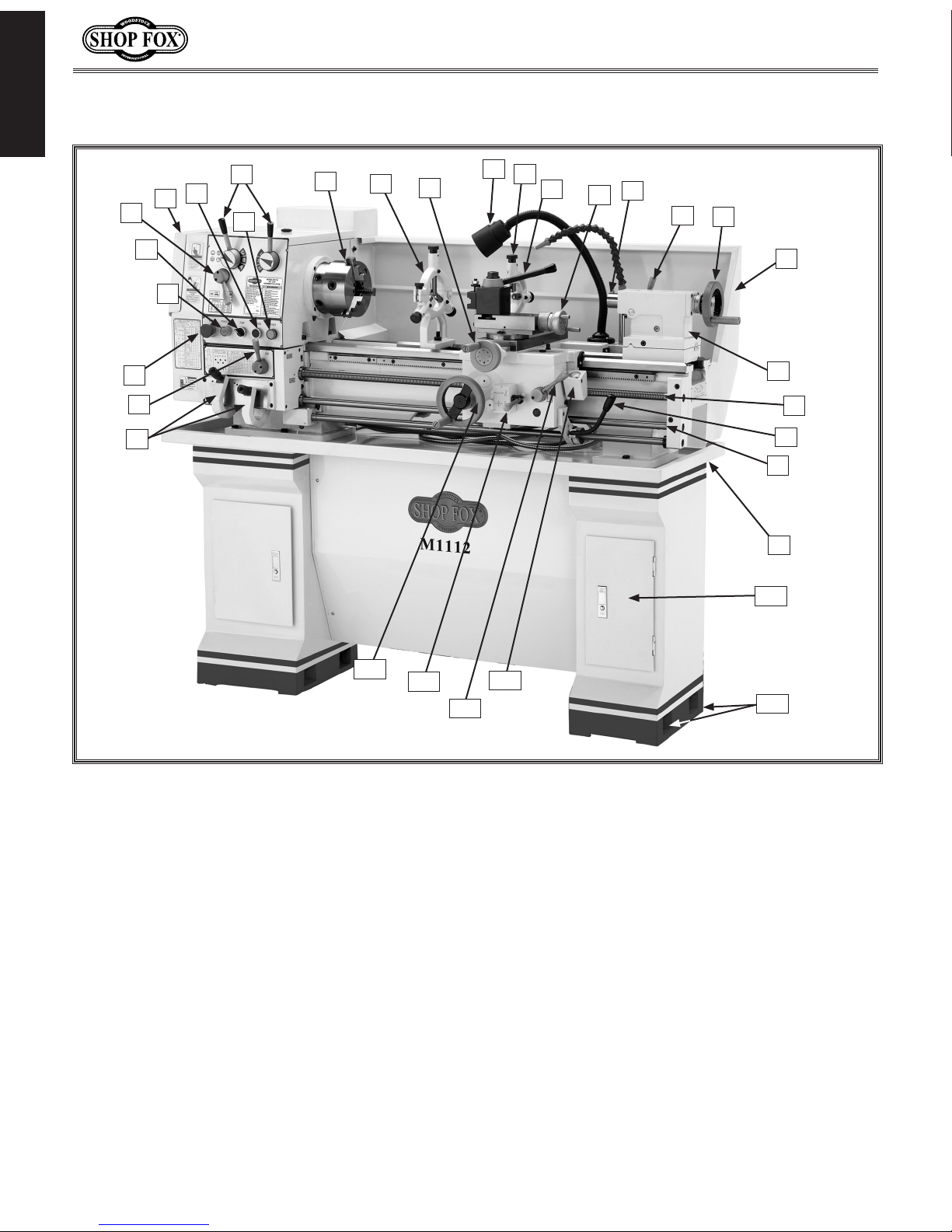
Features:
Easy To Use Lever Controls
Halogen Work Light
Coolant System
Full Length Splash Guard
1
5⁄8"Spindle Bore With 4 Brass Tipped Outboard Screws For Outboard Support
1⁄2"Square Drive Stud Tailstock Lock
Gears Flame Hardened And Ground

-6-
M1112 12" x 36" Gunsmithing Lathe
INTRODUCTION
Model M1112 lathe.
Controls and Features
A. Quick Change Gearbox Levers
B. Feed Rod Lever
C. Emergency Stop/RESET Button
D. POWER START Button
E. Pump Switch
F. Feed Direction Lever
G. Gear and Belt Cover
H. Inching/Jog Button
I. Power Light
J. Spindle Speed Levers
K. 3-Jaw Chuck
L. Steady Rest
M. Cross Feed Handwheel
N. Halogen Work Light
O. Follow Rest
P. Tool Rest
Q. Compound Rest Handwheel
R. Tailstock Spindle and Center
S. Tailstock Spindle Lock Lever
T. Tailstock Spindle Handwheel
U. Back Splash Guard
V. Tailstock
W. Leadscrew
X. Spindle Rotation ON/OFF Lever
Y. Feed Rod
Z. Chip Tray
AA. Storage Cabinet
BB. Stand Mounting Points
CC. Thread Dial
DD. Half-nut Lever
EE. Apron/Cross Feed Lever
FF. Carriage Handwheel
D
E
FG
I
JKLM
NOPQR
ST
U
V
W
X
Y
Z
A
B
C
AA
CC
DD
EE
FF
BB
H

-7-
M1112 12" x 36" Gunsmithing Lathe
SAFETY
SAFETY
READ MANUAL BEFORE OPERATING MACHINE.
FAILURE TO FOLLOW INSTRUCTIONS BELOW WILL
RESULT IN PERSONAL INJURY.
Standard Safety Instructions
1. Thoroughly read the Instruction Manual before operating your machine. Learn the applications,
limitations and potential hazards of this machine. Keep the manual in a safe and convenient place
for future reference.
2. Keep work area clean and well lighted. Clutter and inadequate lighting invite potential hazards.
3. Ground all tools. If a machine is equipped with a three-prong plug, it must be plugged into a
three-hole grounded electrical receptacle or grounded extension cord. If using an adapter to aid in
accommodating a two-hole receptacle, ground using a screw to a known ground.
4. Wear eye protection at all times. Use safety goggles with side shields or safety goggles that meet
the appropriate standards of the American National Standards Institute (ANSI).
5. Avoid dangerous environments. Do not operate this machine in wet or open flame environments.
Airborne dust particles could cause an explosion and severe fire hazard.
6. Ensure all guards are securely in place and in working condition.
7. Make sure switch is in the OFF position before connecting power to machine.
8. Keep work area clean, free of clutter, grease, etc.
9. Keep children and visitors away. Visitors must be kept at a safe distance while operating unit.
10. Childproof your workshop with padlocks, master switches or by removing starter keys.
11. Stop and disconnect the machine when cleaning, adjusting or servicing.
Indicates an imminently hazardous situation which, if not avoided, WILL
result in death or serious injury.
Indicates a potentially hazardous situation which, if not avoided, COULD
result in death or serious injury.
Indicates a potentially hazardous situation which, if not avoided, MAY
result in minor or moderate injury.
This symbol is used to alert the user to useful information about proper
operation of the equipment, and/or a situation that may cause damage
to the machinery.
NOTICE

-8-
M1112 12" x 36" Gunsmithing Lathe
SAFETY
12. Do not force tool. The machine will do a safer and better job at the rate for which it was
designed.
13. Use correct tool. Do not force machine or attachment to do a job for which it was not designed.
14. Wear proper apparel. Do not wear loose clothing, neck ties, gloves, jewelry, and secure long hair
away from moving parts.
15. Remove chuck keys, rags, and tools. Before turning the machine on, make it a habit to check
that all chuck keys and wrenches have been removed.
16. Keep proper footing and balance at all times.
17. Lock the mobile base from moving before feeding the workpiece into the machine.
18. Do not leave machine unattended. Wait until it comes to a complete stop before leaving the
area.
19. Perform machine maintenance and care. Follow lubrication and accessory attachment
instructions in the manual.
20. Keep machine away from open flame. Operating machines near pilot lights or open flames
creates a high risk if dust is dispersed in the area. Dust particles and an ignition source may cause
an explosion. Do not operate the machine in high-risk areas, including but not limited to, those
mentioned above.
21. If at any time you are experiencing difficulties performing the intended operation, stop using the
machine! Then contact our technical support or ask a qualified expert how the operation should be
performed.
22. Be aware that certain materials may cause an allergic reaction in people and animals,
especially when exposed to fine dust. Make sure you know what type of material dust you will be
exposed to and the possibility of an allergic reaction.
23. Habits—good and bad—are hard to break. Develop good habits in your shop and safety will
become second-nature to you.

-9-
M1112 12" x 36" Gunsmithing Lathe
SAFETY
Additional Safety Instructions for Lathes
USE this and other machinery with caution
and respect. Always consider safety first,
as it applies to your individual working
conditions. No list of safety guidelines can
be complete—every shop environment is
different. Failure to follow guidelines could
result in serious personal injury, damage
to equipment or poor work results.
READ and understand this
entire instruction manual
before using this machine.
Serious personal injury
may occur if safety and
operational information is
not understood and fol-
lowed. DO NOT risk your
safety by not reading!
1. AVOIDING INJURY: Read and understand this manual before operating this machine.
2. SAFE CLEANING: Do not clear chips by hand. Use a brush to avoid lacerations, and never clear
chips while the lathe is turning, or entanglement may occur.
3. USING CORRECT TOOLING: Always select the right tool bit for the job, and make sure cutting
edges are sharp. Dull or incorrect bits can break and become a projectile causing severe injury.
4. USING CHUCK KEY CORRECTLY: Never walk away from the lathe with the key in the chuck. An
accidental start can throw the chuck key with great velocity causing severe injury.
5. SECURING A WORKPIECE: Make sure workpiece is properly held in chuck before starting lathe. A
workpiece thrown from the chuck will cause severe injury.
6. CHUCK SAFETY: Get assistance when installing large chucks. Large lathe chucks are very heavy
and awkward to hold and may cause injury from dropping or lifting incorrectly, so protect your
hands and the precision ground ways. Always use a chuck cradle or piece of plywood over the bed
and ways to prevent accidental damage.
7. WORKPIECE SUPPORT: Support a long workpiece if it extends from the headstock so it will not
wobble violently when the lathe is turned on. A workpiece that extends more than 2.5 times its
diameter must be supported by a center or steady rest or it may be thrown from the lathe.
8. AVOIDING STARTUP INJURIES: Make sure workpiece, cutting tool, and tool post have adequate
clearance before starting lathe. Check chuck clearance and saddle clearance before starting the
lathe. Make sure spindle RPM is set correctly for part diameter before starting the lathe. Large
parts can be ejected from the chuck if the chuck speed is set too high.
9. AVOIDING OVERLOADS: Always use the appropriate feed and speed rates. Otherwise you may
break tooling or eject a workpiece causing severe injury.
10. AVOIDING ENTANGLEMENT INJURIES: Never attempt to slow or stop the lathe chuck by hand, and
tie back long hair, ponytails, loose clothing, and sleeves so they do not dangle.
11. MAINTAINING A SAFE WORKPLACE: Never leave lathe unattended while it is running, or coworkers
or passers by may be injured severely.
12. PREVENTING LATHE CRASHES: Disengage the automatic feed levers after completing a job.

-10-
M1112 12" x 36" Gunsmithing Lathe
SAFETY
Avoiding Potential Injuries
Figure 3. Always wear face and eye protection
when using lathes.
Figure 2. Never walk away from the lathe with
the chuck key inserted in the chuck.
Figure 1. Always protect the bed ways, and
unplug the lathe when retooling the lathe.
Figure 4. Never use hands to stop or slow the
chuck when shutting down the lathe.
Figure 5. Never wear loose clothing or gloves
when working with the lathe.

-11-
M1112 12" x 36" Gunsmithing Lathe
ELECTRICAL
ELECTRICAL
DO NOT work on your electrical system
if you are unsure about electrical
codes and wiring! Seek assistance from
a qualified electrician. Ignoring this
warning can cause electrocution, fire,
or machine damage.
220V Operation
The Model M1112 is wired for 220V single-phase operation.
We recommend connecting this machine to a dedicated
circuit with a verified ground, using the circuit size given
below. Never replace a circuit breaker with one of higher
amperage without consulting a qualified electrician to
ensure compliance with wiring codes. This machine must
be connected to a grounded circuit!
A plug is not supplied with this machine. See below for
the recommended plug type for this machine.
If you are unsure about the wiring codes in your area
or you plan to connect your machine to a shared cir-
cuit, you may create a fire or circuit overload hazard—
consult a qualified electrician to reduce this risk.
We do not recommend using an extension cord; however,
if you have no alternative, use the following guidelines:
• Use a cord rated for Standard Service (S).
• Do not use an extension cord longer than 50 feet.
• Ensure that the cord has a ground wire and pin.
• Use the gauge size listed below as a minimum.
Extension Cords
Operating Voltage Amp Draw Min. Circuit Size Recommended Plug Extension Cord
220V Operation 10 Amps 15A NEMA 6-15 (not incl.) 14 Gauge
Figure 6. 6-15 plug and receptacle.
6-15P 6-15R
Electrical Specifications
The machine must be properly set up before it is
safe to operate. DO NOT connect this machine to the
power source until instructed to do so in the "Test
Run" portion of this manual.

-12-
M1112 12" x 36" Gunsmithing Lathe
SET UP
Main Components (Figure 7) Qty
A. 6" Three-Jaw Chuck w/Jaws.............................1
B. Steady Rest .................................................1
C. Follow Rest .................................................1
D. Quick Change Tool Post...................................1
E. Cabinet Base:
—Cabinets (Left & Right).................................2
—Front Panel ...............................................1
—Front Panel Brackets....................................2
Accessory Components (Figure 8)
F. 8" Four-Jaw Universal Chuck ............................1
G. 10" Faceplate...............................................1
H. Oil Bottle ...................................................1
I. Tool Box .....................................................1
J. Three-Jaw Chuck Jaws ...................................3
K. Tailstock Wrench...........................................1
L. 3- and 4-Jaw Chuck Wrenches.......................1 EA
M. Square Socket T-Wrench..................................1
N. Quick Change Tool Holder................................1
O. Change Gears ..............................................1
—Gear 27-Tooth ............................................1
—Gear 26-Tooth ............................................1
—Gear 35-Tooth ............................................1
—Gear 40-Tooth (Installed) ..............................2
—Gear 45-Tooth ............................................1
—Gear 50-Tooth ............................................1
—Gear 60-Tooth ............................................1
—Gear 86/91-Tooth (Installed) ..........................1
P. Hex Wrench Set 2, 4, 5, 6, 8, 10 mm ..............1 EA
Q. Wrenches 9/11, 10/12, 12/14, 17/19mm .........1 EA
R. Handwheel Handles .......................................2
S. Dead Center Spindle Sleeve .............................1
T. Arbor B16 to MT#3 ........................................1
U. Standard Dead Center MT#3 .............................1
V. Carbide Tipped Dead Center MT#3 .....................1
W. Live Center MT#3..........................................1
X. #2 Phillips & Standard Screwdrivers................1 EA
Y. Drill Chuck B16 1.5-13mm ...............................1
Z. Drill Chuck Key.............................................1
AA. Spider Screws ..............................................4
BB. Camlock Stud Kit ..........................................1
CC. Cabinet Base Fasteners:
—Hex Bolts M12-1.75 x 40................................6
—Flat Washers 12mm .....................................6
—Phillips Head Screws M6-1 x 10 ..................... 12
—Hex Nuts M6-1............................................4
—Flat Washers 6mm..................................... 12
Inventory
SET UP
Figure 8. Packaged components.
H
FI
G
L
K
V
W
T
U
S
R
Q
P
O
N
M
J
X
Y
Z
AA CC
If any parts are missing, find the part num-
ber in the back of this manual and contact
Woodstock International, Inc. at (360) 734-
Figure 7. Main contents.
BC
A
E
D
BB

-13-
M1112 12" x 36" Gunsmithing Lathe
SET UP
The Model M1112 lathe has been carefully crated. If
you notice the lathe has been damaged, contact your
authorized SHOP FOX®dealer immediately.
To lift and move the lathe, do these steps:
1. Wrap two lifting straps around the bedway pedestals
and route them behind the feed rod, control rod, and
the lead screw, as shown in Figure 9.
2. Move the apron toward the right to help balance the
load, as shown in Figure 9.
3. Position the chip pan on top of the base assembly so
that the six lathe mounting holes align with top holes
of the cabinets.
4. Un-bolt the lathe from the pallet.
5. Slowly raise the lathe from the pallet, and move it
over the cabinet base to your prepared location.
6. Position the lathe so that the six M12-1.75 x 40
hex bolts and flat washers can be inserted through
the chip pan and partially threaded, but not fully
tightened, into the mounting holes of the cabinets
(see Figure 10).
7. Shim between the lathe and cabinet base as required
to make the ways level at all four corner locations as
indicated with a machinist's level.
8. Fully tighten the six hex bolts to secure the lathe to
the cabinet base.
9. For best results, recheck the ways in 24 hours to
make sure the ways are still level and have not
twisted, and re-shim as required.
10. Install the backsplash with four M6-1 x 10 Phillips
head screws and flat washers.
Uncrating and Lifting
The Model M1112 weighs approximately
1400 lbs. You will need power lifting
equipment and assistance to remove
this machine from the crate and posi-
tion it. Inspect all lifting equipment
and make sure that all is in perfect
working order and is rated for the load
before attempting to lift and move this
lathe. Ignoring this warning may lead to
serious personal injury or death.
Figure 9. Lifting strap locations.
Figure 10. Lathe mounting hex bolts.
NOTICE
If a lathe is not level, the ways can twist out of align-
ment, and cutting operations may be affected. Make
sure that your level is a high-quality machinist's level,
and that all measuring surfaces are perfectly clean.
Recheck the lathe ways in a few weeks to make sure
the floor has not settled. Re-shim as required.

-14-
M1112 12" x 36" Gunsmithing Lathe
SET UP
• Floor Load: Your lathe is a heavy load distributed
in a small footprint, so you must reinforce the floor
if required. The floor MUST be level, or the lathe
frame and ways may twist and distort over time.
• Working Clearances: Consider existing and antici-
pated needs, service panel access, length of rods
to be loaded into the lathe, and space for auxil-
iary stands, work tables or other machinery when
establishing a location for your lathe (see Figure 11
for dimensions).
• Lighting: Lighting should be bright enough to elimi-
nate shadow and prevent eye strain.
• Electrical: Outlets must be located near each
machine, so power cords are clear of high-traffic
areas.
Cleaning Machine
The ways and other unpainted parts of your lathe are
coated with a waxy grease that protects them from
corrosion during shipment. Clean this grease off with a
solvent cleaner or citrus-based degreaser. DO NOT use
chlorine-based solvents such as brake parts cleaner,
lacquer thinner, or acetone—if you happen to splash some
onto a painted surface, you will ruin the finish.
Machine Placement
Figure 11. Minimum wall clearances.
MAKE your shop “child safe.”
Ensure that your workplace
is inaccessible to youngsters
by closing and locking all
entrances when you are
away. NEVER allow untrained
visitors in your shop when
assembling, adjusting or
operating equipment.
ALWAYS work in well-
ventilated areas far from
possible ignition sources
when using solvents to clean
machinery. Many solvents
are toxic when inhaled or
ingested. Use care when
disposing of waste rags
and towels to be sure
they DO NOT create fire
or environmental hazards.
NEVER use gasoline or
petroleum-based solvents
to clean your lathe.
-'
/'
)+
B\\g
Nfibg`\Z\
CfX[`e^8i\X
LefYjkilZk\[
CXk_\
))'M
Jlggcp
*-
:_`gKiXp

-15-
M1112 12" x 36" Gunsmithing Lathe
SET UP
Although not required, we recommend that you
mount your new machine to the floor. Because this is
an optional step and floor materials may vary, floor
mounting hardware is not included. Generally, you can
either bolt your machine to the floor or mount it on
machine mounts. Both options are described below.
Whichever option you choose it will be necessary to use a
precision level to level your machine.
Bolting to Concrete Floors
Anchor studs, lag screw and anchor (Figure 12) are two
popular methods for anchoring an object to a concrete
floor. We suggest you research the many options and
methods for mounting your machine and choose the one
that best fits your specific application.
Mounting to Shop Floor
NOTICE
Anchor studs are stronger and more
permanent alternatives to lag shield
anchors; however, they will stick out
of the floor, which may cause a trip-
ping hazard if you decide to move your
machine at a later point.
Figure 12. Typical fasteners for mounting
to concrete floors.
Lag Screw and Anchor
Anchor Stud

-16-
M1112 12" x 36" Gunsmithing Lathe
SET UP
Test Run & Break-In
The purpose of the test run and break-in is to make sure
the lathe and safety features operate correctly, and
that the lathe can enter service quickly without bearing
damage if heavy work loads are immediately anticipated.
To begin the test run & break-in procedure, do these
steps:
1. Make sure the lathe is lubricated and the headstock
oil level is full. Refer to Lubrication on Page 39.
2. Make sure the chuck is correctly secured to the
spindle. Refer to Mounting Chuck and Faceplate on
Page 21 for details.
3. Disengage the half-nut lever and the feed lever
(Figure 13).
4. Connect power to the machine.
5. Rotate the red stop/RESET button (Figure 14)
clockwise so it pops out.
6. Make sure the spindle rotation ON/OFF lever is in
the central or neutral position (Figure 13).
7. Move the speed levers to Band Iso the spindle will
rotate at 70 RPM (Figure 14).
Make sure all power feed levers and dials are
disengaged before starting the lathe! Thoroughly
familiarize yourself with all the controls and their
functions before using any power feed!
NOTICE
NOTICE
NEVER shift lathe gears when lathe
is operating, and make sure both the
half-nut lever and the feed lever are
disengaged before you start the lathe!
Otherwise the lathe will feed the apron
into the chuck or tailstock causing
severe lathe damage.
Figure 13. Apron controls.
Feed Lever is
Horizontal
(Disengaged)
Half-nut Lever
is Pulled Up
(Disengaged)
Figure 14. Headstock controls.
Speed Levers
Spindle Rotation
ON/OFF Lever

-17-
M1112 12" x 36" Gunsmithing Lathe
SET UP
8. Push the POWER START button, then move
the spindle rotation ON/OFF lever (Figure 13)
down until the chuck turns. The top of the
chuck should turn toward you.
— If you hear squealing or grinding noises,
turn the lathe OFF immediately and correct
any problem before further operation.
— If the problem is not readily apparent,
refer to Troubleshooting on Page 42.
9. Push the emergency stop button.
— If the lathe does not stop, turn the lathe
OFF with the spindle rotation ON/OFF
lever, and disconnect the lathe from power.
Refer to Troubleshooting on Page 42 for
correction.
10. Return the spindle rotation ON/OFF lever
to STOP, reset the emergency stop button,
restart the lathe, and let the lathe run for a
minimum of 10 minutes in both directions.
11. Turn the lathe OFF, and move the speed
levers to Cand Iso the spindle will rotate at
200 RPM. Run the lathe in both directions for
10 minutes.
12. Repeat Step 9 for the remaining RPM ranges,
progressively increasing in RPM. When these
steps are complete, the lathe is broken in.
13. Drain and refill the lubricant in the
headstock with Mobil DTE®Oil or an
equivalent. Refer to Lubrication on Page 39
for steps and apron oil change interval.

-18-
M1112 12" x 36" Gunsmithing Lathe
SET UP
Tailstock
Figure 15. Finished dead center.
Figure 16. Bar stock mounted on centers.
Figure 17. Adjusting for headstock end
taper.
Looking down from above.
The tailstock alignment was set at the factory with the
headstock. However, we recommend that you take the
time to ensure that the tailstock is aligned to your own
desired tolerances.
To align the tailstock, do these steps:
1. Center drill a 6'' long piece of bar stock on both
ends. Set it aside for use in Step 4.
2. Make a dead center by turning a shoulder to make
a shank. Flip the piece over in the chuck and turn a
60° point (see Figure 15). As long as it remains in
the chuck, the point of your center will be accurate
to the spindle axis.
Note: Keep in mind that the point will have to be
refinished whenever it is removed and returned to
the chuck.
3. Place the live center in your tailstock.
4. Attach a lathe dog to the bar stock from Step 1 and
mount it between the centers (as shown in Figure
16).
5. Turn approximately 0.010" off the diameter.
6. Mount a dial indicator so that the plunger is on the
tailstock barrel (Figure 17).
7. Measure the stock with a micrometer. If the stock is
wider at the tailstock end, the tailstock needs to be
moved toward the cutter the amount of the taper
(Figure 17).
— If the stock is thinner at the tailstock end, the
tailstock needs to be moved away from the
operator by at least the amount of the taper
(Figure 18).
Table of contents
Other Shop fox Lathe manuals

Shop fox
Shop fox M1015 User manual

Shop fox
Shop fox W1836 User manual

Shop fox
Shop fox M1117 User manual

Shop fox
Shop fox SHOP FOX M1049 User manual

Shop fox
Shop fox M1099 User manual

Shop fox
Shop fox W1852 User manual

Shop fox
Shop fox SHOP FOX M1049 User manual

Shop fox
Shop fox SHOP FOX M1016 User manual

Shop fox
Shop fox W1807 User manual
Popular Lathe manuals by other brands

Jet
Jet JWL-1221VS operating instructions

Clarke
Clarke WOODWORKER CWL1000CF Operating and maintenance instructions

Sima
Sima STAR 16 Original user guide

tornos
tornos MultiDeco 26/6 installation guide

Van Norman
Van Norman 204 Instruction manual and parts list

CHESTER
CHESTER Crusader Deluxe Lathe Operation manual