Midwest Industries, Inc. Ida Grove, IA 51445 800.859.3028 www.shorestation.com 0003231
Page 2 REV A 1/25/05
Bundles Required
SS1062
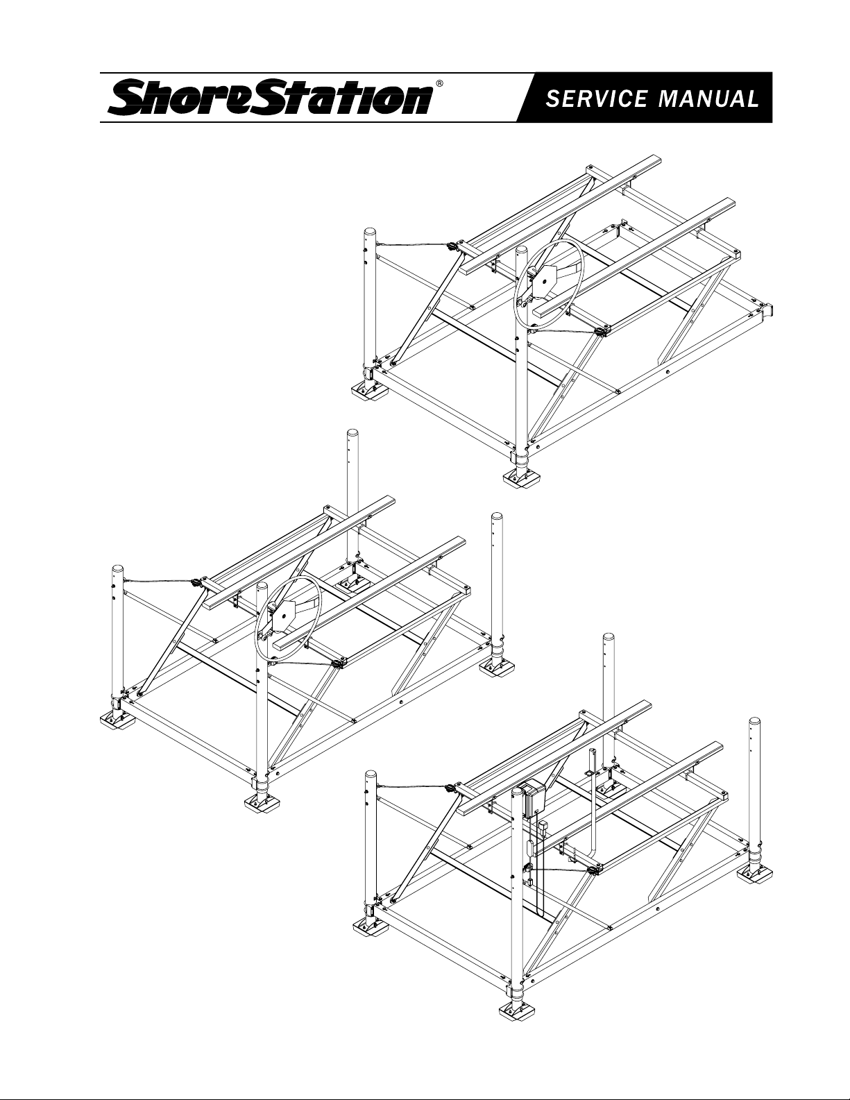
Free Standing Hoist
63701 Platform Bundle
6498901 Wheel Assembly, 30”
68145 Lower Frame
68155 Hardware Box
68154 Leg Bundle
SS10621
Free Standing Hoist for PWC & Fishing Boats
63701 Platform Bundle
6498901 Wheel Assembly, 30”
68145 Lower Frame
68146 Hardware Box
68147 Leg Bundle
SS10621E
Free Standing Hoist for PWC & Fishing Boats
with Electric Drive Winch
63701 Platform Bundle
6498901 Wheel Assembly, 30”
68145 Lower Frame
68146 Hardware Box
68147 Leg Bundle
Accessories / Options
SS8523 Adjustable Leg Bundle
SS8525 Optional Leg Bundle - 80” Legs
SS1226 Electric Winch Kit
CF13-62 Canopy Frame
CC13-62 Vinyl Canopy
SS1062 Assembly Instructions
STEP 1: Open hardware box #68155 and organize
components.
STEP 2: Open lower frame bundle #68145; position
the lower frames on a flat surface (Diagram V,
page 3).
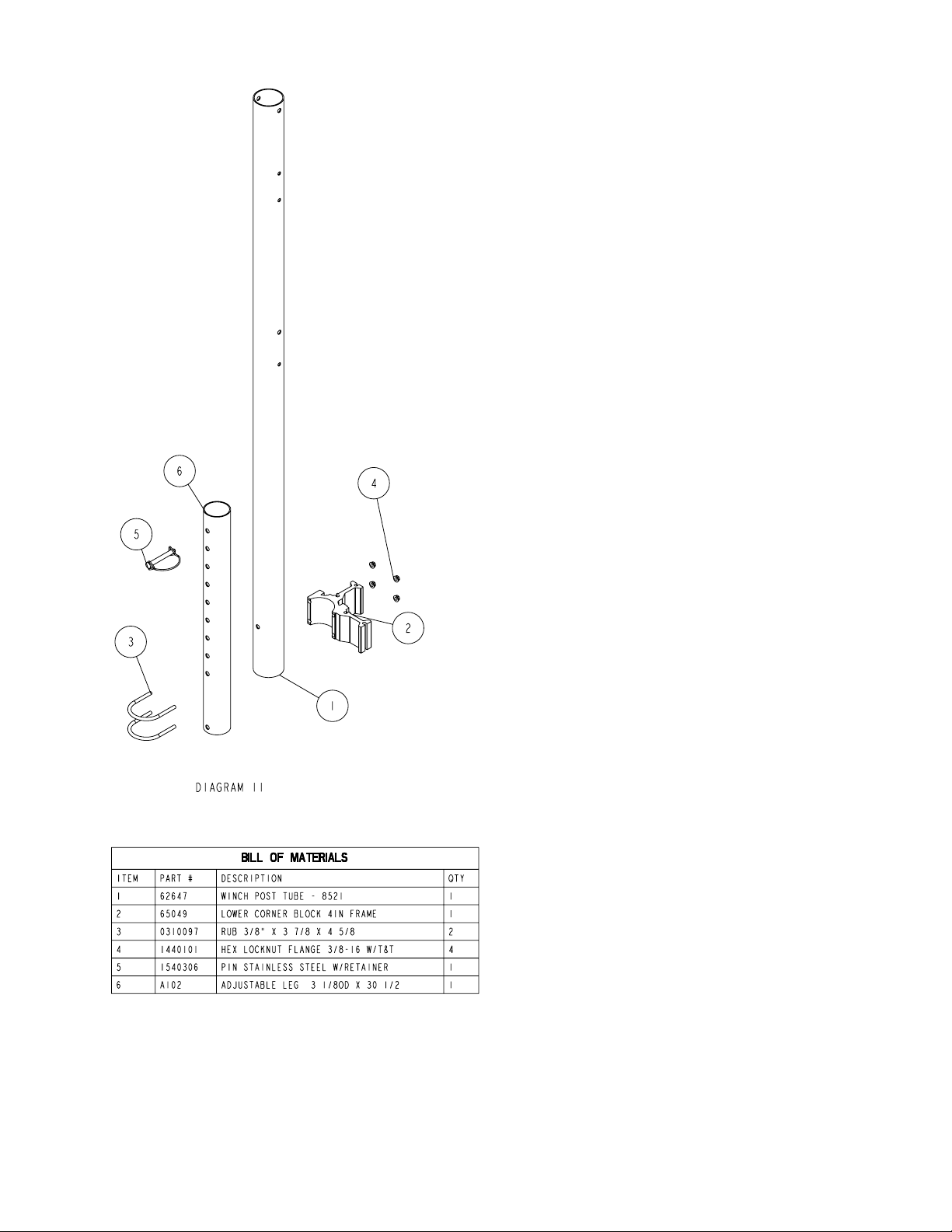
STEP 3: Open leg bundle #68154. Some assembly of the
component parts has been factory assembled.
(Diagram V, Page 3) The two upright posts are
identical except for the orientation when the
corner block was assembled. Separate and
identify their location as shown.
STEP 4: Attach the aluminum base pad channel clamp
(Ref.#10) to the square base pad (Ref.#1) with
two 3/8” X 3/4” carriage bolts and 3/8” hex
flange nuts (Detail A). Tighten. Repeat on
other base pad.
STEP 5: Attach the base pad assembly just assembled
to the bottom of the adjustable leg with a 1/2”
X 4-1/2” hex bolt and 1/2” hex flange lock nut.
Tighten. Repeat on other leg.
STEP 6: Position the two corner post legs as shown
in Diagram V. Slide the lower corner blocks
into the lower frames. Secure by placing a
3/8” flat washer on a 3/8” X 4-1/2” hex bolt.
Place the bolt down through the lower frame
and casting (Detail B, page 4). Secure with
a 3/8” hex flange nut. Do not tighten. Repeat
procedure with the other two corner blocks (De-
tail M, page 3).
LOWER FRAME AND UPRIGHT POST ASSEMBLY
INSTRUCTIONS: