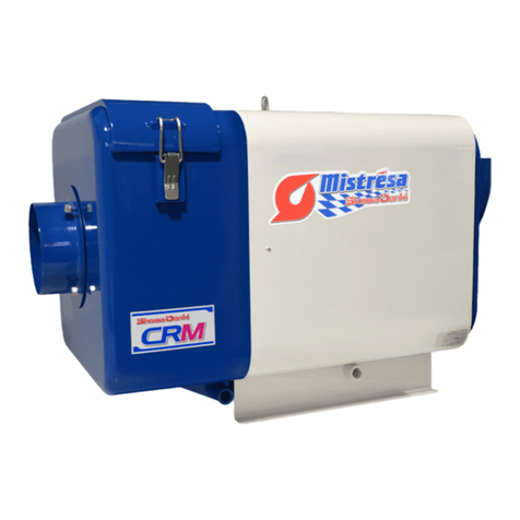
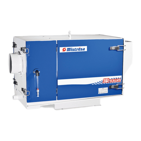
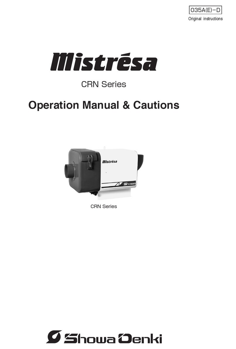
Showa Denki Mistresa CRG Series User manual

取扱説明書・注意書
Operation Manual & Cautions
Original instructions

【目 次】
このたびは、昭和電機のミストレーサをお買い上げいただきありがとうございます。
この取扱説明書・注意書は【CRGシリーズ】の仕様について説明しています。
ミストレーサを『安全』に『効率よく』ご使用いただくために、この取扱説明書・
注意書【特に
マーク部】をよくお読みください。
この取扱説明書・注意書は、大切に保存してご活用ください。

警 告 火災・感電事故を避けるために
警告・指示項目は、必ず守ってください。
警 告 火災・爆発を避けるために
必ずアース線
を接続してく
ださい。
感電注意禁止事項を表
します。
(対象は不特定)
指示の通りに
し てくだ さい 。
取り扱いを誤
ると事故につ
ながる可能性
があります。
分解禁止
警 告 危険場所への設置厳禁
1 .取扱説明書・注意書の見方について
2 .図記号の意味について
3 .
ミストレーサを【安全】にご使用いただくために
本文中の【 警告】マークの部分は、取り扱いを誤ると【死亡や
重傷に結びつく事故】【火災発生】の可能性があるもの。
また、本文中の【 注意】マークの部分は、取り扱いを誤ると【傷
害に結びつく事故】【製品損傷】に結びつくもの。
このミストレーサは耐圧防爆構造品ではありません。爆発性雰囲気とな
る可能性のある場所で運転すると、モータ(電動機)が焼損(焼け
て壊れる)した時、周囲のガスが『爆発』して危険です。
ミストレーサの配線は、必ず電気工事の有資格者が
電気設備技術基準や内線規程に従い施工してください。
は絶対に吸引しないでください。
爆発性ガス 有機溶剤 火気
−1−
本製品は、工作機械等から発生するオイルミストを捕集し、快適な作業
環境を確保するための商品です。本来の目的以外では使用しないでくだ
さい。

警 告 回転中の保守・点検禁止
本体内部の確認や点検は、羽根車の回転が停止してから
行ってください。
注 意 ご使用される際のご注意
CRGシリーズで使用している省エネモータは、標準(IE1またはそれに
準ずる)モータに比べ、損失を低減するために、モータの抵抗が低くな
るように設計されております。それにより、製品によっては始動電流が
増加する場合もあります。弊社標準モータ製品との置き換えを
される場合にはブレーカなどの変更が必要になる場合があります。
入念に検査・点検を行った上で出荷しておりますが、念のためお手元の
ミストレーサについて、次のことをご確認ください。
ミストレーサを保管される場合は下記の環境で保管してください。
屋内で直射日光の当たらない場所
温度0℃〜40℃
湿度10%〜90%(結露なきこと)
長期間(3ヵ月以上)保管・休止する場合は次のことに注意ください。
(1)梱包した状態で保管の場合
屋内の温度変化の少ない、乾燥した場所で保管してください。
(2)据え付けた状態で休止の場合
他の装置からの【大きな振動】や【熱】を受けないようにしてください。
水や油、ほこりなどからミストレーサを守るため、ビニールなどで覆っ
ていただくことをおすすめします。
●
ご注文どおりの製品ですか。
●
輸送中の【破損・変形】など異常はありませんか。
●
付属部品に欠品はありませんか。
4 .納品時のご確認と保管について
取扱説明書・注意書
パッキン
圧着端子(1個予備)
標準付属品 数量
1通
1枚
7個
−2−

CRGシリーズの内部構造と各部の名称
5 .内部構造
(1)製品銘板…………………………本体部
製品形式・定格電圧・定格周波数・定格電流・絶縁クラス・最大静圧・
最大風量・製造番号などの内容を表示しています。
注1:定格とは、使用限度をいいます。
(2)接地(アース)…………端子箱内
マークで表示しています。この部分より必ずアース線を接続して
ください。
6 .各種表示ラベルについて
−3−

屋内に設置してください
製品質量を考慮して十分な設置面強度を確保してください。
強い振動や衝撃を受けないところに設置してください。
傾きのない水平な場所に設置してください。
(1)設置環境
注意
① 必ず【屋内】に設置してください。
② 爆発性雰囲気となる可能性のある場所への設置はできません。
9 .設置について
7 .設置環境条件について
注意
警告
8 .吸引物質について
モータの焼損や部品の劣化などにつながります。
必ず、下記の範囲でご使用ください。
爆発性ガス・有機溶剤・火花、火のついたタバコなどは絶対に吸引させない
でください。爆発・火災・製品の損傷の原因となります。
−4−
周囲温度
吸込温度
相対湿度
高 度
過電圧カテゴリ
材料グループ
汚染度
CRGシリーズ
0℃〜50℃
50℃以下
10%〜90%
1,000m以下
Ⅲ
Ⅲ
3

(2)電源接続
警告
① 電源は、定格電圧・定格周波数でご使用ください。
●
インバータを使用した運転は、モータ焼損防止端子A・Bをインバ
ータ制御回路に組込む等、電動機を保護すれば可能です。
また、異電圧(380V以上)でインバータ運転される場合は、モータ
絶縁強化が必要になります。
●
電圧変動の許容範囲
連 続……定格電圧の±5%以内
一時的……定格電圧の±10%以内
② 必ず【アース線】を接続してください。
③ 羽根車の回転方向は、吸込側より見て右回転となります。回転方向を
確認した上で運転してください。
④ 端子台の端子A・B(白のリード線付)はモータの焼損防止用の端子
です。使用方法は⑶のとおりです。
⑤ 圧着端子を使用の場合には、圧着端子のカシメ部分に必ず絶縁チュー
ブをかぶせるか、絶縁タイプの圧着端子をご使用ください。
⑥ 電源配線を行う際は必ず端子箱についているコードロックを使用し電
源配線してください。
手順
1.付属のブッシュから
コードに適合するサ
イズを選択する。
2.コードロックにコードを通す。
3.締付バンドを締めてコードを固定し、コードが固定されている
ことを確認する。
ネジサイズ
M3.5
締付トルク
0.87N・m(max0.96N・m)
−5−
ブッシュ記号
S
M
なし
適合コード径(mm)
6.0〜8.0
8.0〜10.0
10.0〜12.0

(3)焼損防止用端子の使用方法
モータの巻線に、熱反応式のサーマルプロテクタを取り付けています。
(巻線温度が異常に上昇すると接点が開き、一定の温度まで下がると接
点が閉じる自動復帰式です)このサーマルプロテクタにつながる端子が
焼損防止用端子A、Bです。
この端子を電磁開閉器(サーマルリレー付)の操作回路に直列に接続す
ることにより、モータ焼損を防止します。
注意
① A、B端子は必ず操作回路に使用し、モータを保護してください。
② 接点定格(AC115V 18A/AC230V 13A/DC24V 18A)以下でご使用
ください。
③ サーマルリレーがトリップした場合は、その原因を取除き、リセット
ボタンを押してください。
a 焼損防止用端子A、Bを用いての配線例
電磁開閉器(サーマルリレー付)をご用意ください。
b 別売のスイッチ(3SWサーマル内蔵、コード3m付)を用いての配線例
−6−
}

10 .ご使用上の注意について
(1)火災防止のため、爆発性ガス・有機溶剤・火花、火のついたタバコなど
を吸引しないでください。
(2)ミストが【油性】(非水溶性)で、吸い込む量が多い場合や、粒子径が小
さい場合など、使用条件により捕集効率が変わり、吹き漏れや、再飛散
を生じることがありますので、オプション部品の【汎用アフターフィル
タ】をご使用ください。なおアフターフィルタの取付けにはアダプタが
必要です。
(3)吸込口の詰まりなどで閉そく状態(空気が流れない状態)にならないよ
うに注意してください。空気の流れにより、内蔵モータを冷却(空冷式)
していますので閉そく状態になるとモータの冷却が悪くなりモータ焼損
の原因となります。
11 .保守点検について
定期点検
3ヵ月を目安に、振動・異常音発生の有無、1年毎に絶縁を点検してく
ださい。
12 .保証について
(1)保証の範囲
取扱説明書、本体貼付ラベル等の注意書きに従った使用状態で保証期間
内に故障した場合には、無料修理をさせていただきます。
ただし、本製品がお客様の他の装置に組み込まれている場合において、
その装置等からの取り外しおよび装置等への取り付け、その他これらに
付帯する工事費用、輸送等に要する費用ならびにお客様に生じた機会損
失、操業損失、その他の間接的な損害については保証範囲外となります。
−7−

(2)保証期間
製品納入日から12ヶ月といたします。
(3)保証期間内でも次の場合には原則として有料修理にさせていただきます。
①取扱説明書、本体貼付ラベル等の注意書によらない使用上の誤り及び
不当な修理や改造による故障及び損傷
②お買上後の輸送、落下等による故障及び損傷
③火災、地震、風水害、落雷、その他天災地変、異常電圧、指定外の使
用電源(電圧、周波数)等による故障及び損傷
④弊社以外での修理、改造(製品への穴あけなどを含む)による故障及
び損傷
⑤弊社指定品以外の部品をご使用の場合の故障及び損傷
⑥異物混入による故障及び損傷
⑦経年変化または使用に伴う変色、傷、消耗部品の自然消耗等の不具合
(4)この製品のご使用中に発生した不具合に起因する損害は補償いたしませ
ん。
13 .お問い合わせについて
(1)本機のお問い合わせは裏面に記載の海外グループへご連絡下さい。
(2)本機の不具合又は修理などのご依頼は裏表紙に記載の海外グループ迄
ご連絡ください。その際は銘板に記載してある品名(TYPE)と製造番号
(№)をご連絡ください。
−8−

14 .仕様一覧
CRGシリーズ
−9−
形 式
電 源
出 力
kW
周波数
Hz
電 流
A
騒 音
機側1m
dB(A)
質 量
㎏
CRG
−
H02
0.2
50/60
1.6/1.3/1.3
67/70
20
CRG
−
H04
0.4
50/60
1.5/1.9/1.9
65/68
30
CRG
−
H10
1.0
50/60
2.9/3.7/3.7
71/77
41
CRG
−
H15
1.5
50/60
4.8/5.0/5.0
71/75
56
三相 50Hz 200V
60Hz 200V
/
220V
※1上記電圧以外の仕様は納入仕様書をご確認ください。
※1
※2
※2動作条件:全負荷
測定方法:機械指令2006/42/ECの1.7.4.2項による

1.
2.
3.
4.
5.
6.
7.
8.
9.
10.
11.
12.
13.
14.
11
11
11
13
14
14
15
15
15
18
18
19
20
20
Cautionary information indications used in this manual .................
Meanings of symbol marks used in this manual .............................
Using the Mistresa in a safe manner ..............................................
Items to check upon product delivery and storage .........................
Internal configuration ......................................................................
Product labels .................................................................................
Ambient conditions in the area of installation .................................
Suction port cautions ......................................................................
Product installation .........................................................................
Operating cautions .........................................................................
Maintenance and inspections .........................................................
Warranty .........................................................................................
Inquiries ..........................................................................................
Specifications .................................................................................
[Contents]
Thank you for purchasing the Mistresa from Showa Denki. This manual explains the
specifications for the CRG Series.
Please read the operating instructions and cautionary information carefully to ensure that the
Mistresa is used in a safe and efficient manner. Special attention should be given to
cautionary information which bears the [ ] mark.
Keep this manual in a secure location
where it can be easily accessed.
−10−

All warnings and instructions
must be strictly observed.
A prohibited action
(Target is unspecified)
Failing to heed the
instructions could
result in accidents
Follow instructions
carefully
Disassembly prohibited
Electrical shock hazardElectrical ground required
WARNING Do not install in hazardous locations
1.
Cautionary information indications used in
this manual
2.
Meanings of symbol marks used in this manual
3.
Using the Mistresa in a safe manner
"[ ] WARNING" mark indicates cautionary information that, if not
heeded, could result in serious injury or death, and could also
pose a fire hazard.
A "[ ] CAUTION" mark indicates cautionary information that, if not
heeded, could result in injury and/or equipment damage.
The Mistresa does not have a pressure and explosion-proof construction.
Operating the Mistresa in areas where explosive gases, etc., are present
could result in an explosion in the event of an electric motor burnout.
−11−
This product collects oil mist generated by equipment such as machine tools
to ensure and maintain a comfortable working environment. Do not use the
product for any purpose other than the originally intended.

WARNING Fire and explosion prevention
Never allow explosive gases, organic solvents, or flames to be sucked
into the suction port.
CAUTION Operating cautions
WARNING Fire and electrical shock prevention
WARNING Maintenance and inspections prohibited
during impeller rotation
The Mistresa wiring work must be performed by a qualified electrician, and must
conform to the relevant electrical engineering standards and
internal wiring standards.
Be sure that impeller rotation has completely stopped before performing
internal maintenance and inspections.
WARNING Fire and explosion prevention
WARNING Do not install in hazardous locations
The Mistresa does not have a pressure and explosion-proof construction.
Operating the Mistresa in areas where explosive gases, etc., are present
could result in an explosion in the event of an electric motor burnout.
Never allow explosive gases , organic solvents , or flames to be sucked
into the suction port.
The CRG series is equipped with an energy-saving motor which reduces energy
loss (as compared to the standard IE1 or equivalent motor), thereby lowering the
motor's resistance. Because this may increase the starting current depending on
the product being used, it may be necessary to change the breaker, etc., when a
product which has a standard Showa Denki motor is replaced with
a CRG series product.
−12−

4.
Items to check upon product delivery and storage
Although all our products are thoroughly tested and inspected prior to
shipment, the customer should nonetheless check the following items when
taking delivery of the Mistresa.
If necessary, store the Mistresa in ambient conditions below.
・Indoor avoiding direct sun beams
・Temperature between 0°C to 40°C
・Humidity between 10% to 90% (No condensation)
Follow the instructions below if it is necessary to stop the operation or store
the Mistresa for 3 months or longer.
(1) Storing Mistresa in the original packaging
Store the Mistresa in a dry area indoor where the temperature does not
change much.
(2) Not operating the Mistresa after installation
Keep the Mistresa free from "significant vibration" and "heat" from
other machines and equipment.
It is recommended that the Mistresa be covered with a plastic sheet or the
like to keep it free from water, oil and dust.
• Verify that the delivered product (model, etc.) is the same as
that which was ordered.
• Verify that the product has not been damaged or deformed,
etc., during shipment.
• Verify that all the product accessories are present.
Operation Manual & Cautions
Packing
Crimp terminal (1 spare)
Standard Accessories Quantity
1 copy
1 piece
7 pieces
−13−

5.
Internal configuration
The CRG series internal configuration and part names are shown below.
Suspension eye-bolt
Discharge port
Wire screen
Demister
Motor
Impeller
Wire screen
Ceiling plate
Main body
Terminal box
Bottom plate
Drain port
Packing
Suction port
6.
Product labels
(1) Product nameplate………On main body
The nameplate label contains the following information: product model,
rated voltage, rated frequency, rated current, insulation class, max. static
pressure, max. airflow rate, manufacture No., etc.
Note 1: The "ratings" are the operating limit values.
(2) Ground connection………Inside the terminal box
The " " mark indicates a ground connection.
Be sure that the mark-indicated part is securely grounded.
−14−

Never allow explosive gases, organic solvents, sparks, or burning cigarettes
to be sucked into the suction port. These materials could cause explosions,
fires, and product damage.
WARNING
8.
Suction port cautions
9.
Product installation
(1) Installation environment
CAUTION
①This product must be installed indoors only.
②Do not install in an environment where explosive gases, etc., may be
present.
−15−
7.
Ambient conditions in the area of installation
CAUTION
Ambient temperature
Intake temperature
Relative humidity
Altitude
Overvoltage category
Material group
Level of contamination
CRG Series
0°C to 50°C
50°C or lower
10% to 90%
1,000 meters or lower
III
III
3
・Install the Mistresa indoor.
・Make sure that the installation floor has a sufficient bearing
strength commensurate with the machine weight.
・Install the Mistresa where it stays away from strong vibration
or impact.
・Install the Mistresa on a level, flat surface.
Resulting in motor burnout and deterioration of the components.
Be sure to use within the range described following.

Installation nut Main body
Bush S Bush M
Fastener band
Screw size
M3.5
Tightening torque
0.87N·m (max0.96N·m)
(2) Power supply connection
WARNING
①Be sure that the power supply conforms to the rated voltage and rated
frequency requirements.
• When using inverter controlled operation, protect the motor by
incorporating the motor burnout prevention terminals "A" and "B"
in the inverter's control circuit.
In addition, if it is inverter operation at different voltage (more
than 380V), you will need a motor insulation strengthening.
• Permissible voltage fluctuation range:
Continuous…Rated voltage within ±5%
Momentary…Rated voltage within ±10%
②Please connect the ground wire sure.
③The impeller should be rotating in the clockwise direction as viewed
from the suction port side. Verify that the rotation direction is correct
before beginning operation.
④The terminal block's "A" and "B" terminals (with white leads) are for
motor burnout prevention. The method for using these terminals is
described in item 3) below.
⑤ When using crimp terminals, either cover the crimp area with an
insulation tube, or use insulated type crimp terminals.
⑥For the electrical installation and wiring, be sure to use the cord lock
installed on the terminal box.
Procedure
:
1. Select the bush commensurate
with the cord from the
attached bushes.
2. Put the cord through the cord lock.
3. Tighten the fastener band to secure the cord in place. Check that
the cord is securely tightened.
−16−
Bush symbol
S
M
None
Applicable cord diameter
(
mm
)
6.0 to 8.0
8.0 to 10.0
10.0 to 12.0

(3) Using the burnout prevention terminals
The motor winding is equipped with a heat reactive type thermal
protector (the contact automatically opens when the winding
temperature becomes abnormally high, and closes when the temperature
drops to a constant level). The "A" and "B" burnout prevention terminals
are connected to this thermal protector.
By connecting this terminal in series with the operating circuit of the
electromagnetic switch (withthermal relay), to prevent motor burnout.
CAUTION
①Be sure to connect the "A" and "B" terminals to the operation circuit
in order to protect the motor.
② Use the prescribed or lower contact rating (115V AC, 18A / 230V
AC, 13A / 24V DC, 18A).
③ When the thermal relay is tripped, correct the cause, then press the
[RESET] button.
a) Connection example for burnout prevention terminals "A" and "B"
Electromagnetic switch device (with thermal relay) Please prepare.
−17−
Power supply
When using
an electromagnetic
switch
Terminal box
Thermal protector

b) Connection example when using the optional switch with built-in
3SW thermal and a 3m cable)
Power supply
Terminal box
Thermal protector
Switch
10.
Operating cautions
(1) In order to prevent fires, never allow explosive gases, organic solvents,
sparks, or burning cigarettes to be sucked into the suction port.
(2) The collecting efficiency may vary according to the operating conditions
(e.g., when 1sucking in large amounts of an oily mist (non-water-soluble),
or when the particle size is small, etc.), possibly resulting in blow leakage
or re-scattering. To prevent this, the optional general-purpose after
filter should be used. Note that an adapter is required when installing
the after filter.
(3) Use care to prevent the suction port from becoming closed due to
clogging (no air flow). The internal motor is cooled by this air, and a
clogged port could prevent proper motor cooling, possibly resulting in a
motor burnout.
11.
Maintenance and inspections
Periodic inspections
An inspection should be performed every 3 months to check for
abnormal vibration and sounds. The insulation condition should be
checked once per year.
−18−
(cable 3m)
}
Table of contents
Other Showa Denki Industrial Equipment manuals


