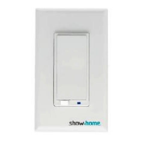
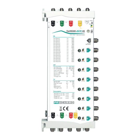
showhome ZW661 User manual

Show HomeProductswarrantsthisproduct tobe free frommanufacturing defectsfor
aperiod of two years fromthe original dateof consumerpurchase. Thiswarrantyislimited
tothe repairorreplacement of thisproduct onlyand doesnot extend toconsequential or
incidental damage tootherproductsthat maybe used withthisproduct.
Thiswarrantyisin lieu of all otherwarranties, expressed orimplied. Somestatesdo not
allow limitationson how long an implied warrantylastsorpermit the exclusion orlimitation
of incidental orconsequential damage, sothe abovelimitationsmaynot applytoyou.
Thiswarrantygivesyou speci
crights, and you mayalsohaveotherrightswhichvaryfrom
statetostate. if the unit should provedefectivewithin the warrantyperiod.
RISK OF FIRE
RISK OF ELECTRICALSHOCK
RISK OF BURNS
CONTROLLING APPLIANCES:
Model:ZW661 EXERCISE EXTREMECAUTIONWHENUSING Z-WAVE
Powersupply: 220 VAC, 50Hz. DEVICES TO CONTROLAPPLIANCES. OPERATION
Signal (Frequency): 868.42 MHz.
OF THEZ-WAVE DEVICEMAY BE INADIFFERENT
Operating Range: Range: Up to100 feet line
ROOMTHANTHECONTROLLEDAPPLIANCE, ALSO AN
Dimension(L*W*H):86*86*39(mm) UNINTENTIONALACTIVATIONMAY OCCUR IF THEWRONG
MaximumLoads: 3200W(15A) Resistive BUTTONONTHEREMOTEISPRESSED. Z-WAVE DEVICES
Wireless Controllerand the closest Z-Wave MAY AUTOMATICALLYBE POWEREDONDUETO TIMED
receivermodule. EVENTPROGRAMMING. DEPENDING UPONTHEAPPLI-
Speci cationssubject tochange without notice ANCE, THESE UNATTENDEDORUNINTENTIONALOP-
due tocontinuing product improvement
ERATIONSCOULD POSSIBLYRESULTINAHAZARDOUS
In-Wall Smart Switch
ZW661 In-Wall Smart Switch
WARRANTY
SPECIFICATIONS
WARNING
due tocontinuing product improvement
ERATIONSCOULD POSSIBLYRESULTINAHAZARDOUS
CONDITION. FORTHESE REASONS, WERECOMMEND
ebsite www.ishowlights.com
DO NOTRETURN THISPRODUCTTO THESTORE
THEFOLLOWING:
DO NOTUSE Z-WAVE DEVICES TO CONTROLELECTRIC
HEATERSORANYOTHERAPPLIANCES WHICH MAY PRES-
ENTAHAZARDOUSCONDITIONDUETO UNATTENDEDOR
UNINTENTIONALORAUTOMATICPOWERONCONTROL.
Safetyand maintenance instruction
1. Make sure that all electric connections and connection cables meet the pertaining regulations and are in
conformity with the operating instruction.
2. Do not overload electrical outlets or extension cords, fire or electric shocks can be the result.
3. Please contact an expert in case you have any doubts about the mode of operation, the safety or connecting
the appliances.
4. Keep all parts away from young children s reach.
5. Do not store this item on wet, very cold or warm places, this can damage the electronic circuit boards.
6. Avoid dropping or shocks, this can damage the electronic boards.
7. Never replace damaged power cables yourself! In such case, remove them from the net and take the devices to
a workshop.
1. Getting To KnowYour NewZ-Wave Device
Turn ON/OFF manually or remotely via the Z-Wave controller
•Can be Included in multiple Groups and Scenes
•Compatible with all incandescent and CFL/ LED bulbs
•Blue LED indicates switch location in a dark room

•Z-Wave Certified for simple pairing and integrated home automation
•Screw Terminal Installation —requires wiring connections for Line (Hot), Load, Neutral.
WARNING SHOCK HAZARD
Turn OFF the power to the branch circuit for the switch and lighting fixture at the service panel. All wiring connections must be
made with the power OFF to avoid personal injury and/or damage to the switch.
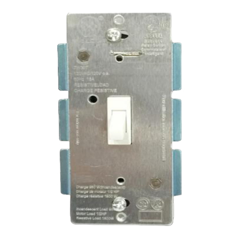
A. Push button
B. Load (Black)
C. Lin (Black) - Line in
D. Nin (White) - Nutral in
Single switch wiring
1. Shut off power to the circuit at circuit breaker or fuse box.
IMPORTANT! Verify power is OFF to switch box before continuing.
2. Remove wall plate.
3. Remove the switch mounting screws.
4. There are up to three screw terminals on the switch; these are marked
B. Load —Black (connected to lighting)
C. Lin —Black (connected to power)
D. Nin —White(Nutral)
5. Observe Important Wiring Information
IMPORTANT!: This switch is rated for and intended to only be used with copper wire. Wire Gauge Requirements
Use larger wires suitable for at least 80°C for supplying Line (HOT), Load, Neutral connections.
Wire strip length:
For attachment to screw terminals: Strip insulation 1", For attachment using the enclosures holes: Strip insulation 5/8"
6. Connect the black wire that goes to the light to the terminal marked Load.
7. Connect the black wire that comes from the electrical service panel (Hot) to the terminal marked Lin.
8. Connect the white wire to the neutral terminal marked Nin (use jumper wire if needed).
9. Insert Switch into the switch box being careful not to pinch or crush wires.
10. Secure the Switch to the box using the supplied screws.
10. Secure the Switch to the box using the supplied screws.
11. Mount the wall plate.
12. Reapply power to the circuit at fuse box or circuit breaker and test the system.
Basic Operation
The connected light can be turned ON/OFF in two ways,
1. Manually from the front button of the In-wall Switch
2. Remotely with a Z-Wave Controller
Manual Control
The Front button allows the user to:
Turn ON/OFF the connected fixture.
To turn the connected fixture ON: Press the button.
To turn the connected fixture OFF: Press the button again.
2. Linking your Z-Wave device
TO return your switch to factory default:
Use controller to remove device fromnetnorwwill reset it to factorydefault
Please use this procedure onlyin the event that the network primarycontroller is missing or otherwise inoperable.
Adding device to e network:
1. Followthe instructions ofcertified controller to include a device fromdifferent manufactures to the Z-Wave network.
2. Once the controller is readyto include your device, press the button to include it in the network.
3. Once your controller has confirmed that the device has been included, refresh
the Z-Wave network to optimize performance.
4. The device is associated in the same group when it included in setting process.Nowyou can control your
Z-Wave device according to groups, scenes, schedules and automation programmed. Ifyour controller features remote access,
you can nowcontrol all devices in Z-Wave network frommobile devices.
To exclude and reset the device

1. Followthe instructions for your Z-Wave certified controller to exclude a device fromthe Z-Wave network.
2. Once the controller is readyto Exclude your device, press the button to exclude it fromthe network.
Note
:
1. Your controller mayneed to be within 10 feet ofthe device to be included.
2. The association group supports five nodes and life line function.
3. This product can be operated in anyZ-Wave network with other Z-Wave certified devices from
other manufacturers. All non-batteryoperated nodes within the network will act as repeaters
regardless ofvendor to increase reliabilityofthe network.
Package content
In-wall Smart Switch-1pcs
Screw-3 pcs
Installation Operation manual-1pcs
Other showhome Switch manuals
Popular Switch manuals by other brands
Digitus
Digitus DN-50012-1 user manual
Hytronik
Hytronik HE2050-A instruction manual
Schmalz
Schmalz VSi Series operating instructions

Gewiss
Gewiss RESTART RD 90 Series manual
Coherent Solutions
Coherent Solutions SwitchPXIe 1000 Series user manual
SMC Networks
SMC Networks SMC EZ Switch 10/100/1000 SMCGS8P-Smart Specifications
