SHS HT7 Series User manual

S.H.S. s.r.l. Via F.lli Rosselli, 29 20027 Rescaldina (MI) – ITALY Tel. +39 0331 466918 Fax. +39 0331 466147 www.shsitalia.it
User Guide
STEPPING MOTOR DRIVE
Series
HT7
Models
HT7_X

www.shsitalia.it info:shsbox@shsitalia.it
2
The SHS automation products should be handled, installed and maintained by qualified personnel trained on
installation of automation components, and only for the purposes described in the user manual.
Installers must pay particular attention to the potential risks caused by mechanical and electrical equipment.
It is very important that applications and installations meet all applicable safety requirements.
Each installer has an obligation to take responsibility to verify their knowledge and understanding of
all applicable safety standards.
Any use which does not meet the safety requirements can damage equipment and injure the user.
SHS s.r.l. does not consider itself responsible for, and assumes no liability for damage caused by handling
products and / or improperly installed, or in cases where the customer has allowed, or executed,
modifications and / or repairs not authorized by SHS s.r.l.
The SHS drives are devices for automation high performance capable of generating rapid movements and high forces.
Pay high attention, especially during installation and application development.
Only use equipment properly sized for the application..
The SHS devices are considered components for automation and are sold as finished products to be installed only by
qualified personnel and in accordance with all local safety regulations.
The technicians must be able to recognize possible dangers that may result from programming, by changing parameter
values and generally by the mechanical, electrical and electronic.
SHS s.r.l recommends to always follow basic safety rules. Failure to heed them can result in injury to persons
and / or property.
General precautions:
•This manual is subject to change due to product improvement, specification changes or improvements
of the manual
•SHS s.r.l. He is not responsible for damage to property and / or persons caused by faulty installation
and / or unauthorized modifications of the product.
The damaged drive sys- tems must not be installed or put into operation in order to avoid injury
persons and damage to property. Changes or modifications made to the drive systems is prohibited and
It involves the extinction of any right to warranty or of any obligation of responsibility.
Safety notes

www.shsitalia.it info:[email protected]
3
Index
1 TECHNICAL DATA 4
1,1
Powe supply / Moto Connecto
4
1,2
FIELDBUS Connecto
4
1,3
Input/Output Connecto s
5
1,4
DIP-SWITCH and Ethe net Connecto s
6
1,5
Status LEDS
6
1,5
P otection / Display messages
7
1,6
Pa amete s setting
8
1,7
Mechanical dimension
9
2 CONNECTION 10
2,1
Installation note
10
2,2
AC Powe Supply
10
2,3
DC Powe Supply
12
2,4
Input / Outputs
12
2,5
Digital Inputs
14
2,6
Digital Outputs
14
2,7
Encode Inputs
15
2,8 16
2,9
FIELDBUS Inte face
16
3 OPERATING MODE 17
3,1
Step/Di ection Mode
17
4 HT7 MODELS CODE 19
Analog Inputs/ Outputs

www.shsitalia.it info:[email protected]
4
1. TECHNICAL DATA
1.2 FIELDBUS Connector
1.1 Power supply / Motor connector
J1A ( Left )
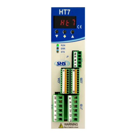
SIGNAL FUNCTION
B2 Phas B2 of th motor
B1 Phas B1 of th motor
A2 Phas A2 of th motor
A1 Phas A1 of th motor
HVI
GND 0V pow r supply
Pow r supply input DC
( conn ct to HV0 or us as input DC pow r )
J1B ( Right )
SIGNAL FUNCTION
AC1
AC2
HV0 R ctifi d output
AUX
SHIELD
0S 0V pow r supply AUX
Pow r supply Vac
Pow r supply Vac
Logic pow r supply input
( conn ct to HV0 or us an pow r
supply xt rnal from +24 to 140Vdc )
Schi ld
J3 SIGNAL FUNCTION
1 0V S rial GND ( isolat d )
2 CL CAN BUS L
3 RS- RS485 - ( Half dupl x )
4 CH CAN BUS H
5 RS+ RS485 + ( Half dupl x )

www.shsitalia.it info:[email protected]
5
1.3 Input / Output Connectors
J2A (Left) SIGNAL FUNCTION
1 ENC_AH Encod r A+
2 ENC_AL Encod r A-
3 ENC_BH Encod r B+
4 ENC_BL Encod r B-
5 ENC_ZH Encod r Z+
6 ENC_ZL Encod r Z-
7 ENC_COM Encod r common (don’t us in diff r ntial mod )
8 ENA/DIS Input ENABLE/DISABLE
9 IN3 Input IN3 - (CURRENT REDUCTION)
10 IN2 Input IN2 - (DIRECTION)
11 IN1 Input IN1 - (STEP IN)
J2B (Right) SIGNAL FUNCTION
12 OUT_COM Output common (OUT1, OUT2, OUT3)
13 OUT1 Output OUT1 - (d fault motor St p Out)
14 OUT2 Output OUT2 - (d fault Driv R ady)
15 OUT3 Output OUT3 - (d fault unus d)
16 IN_COM Input common (IN1, IN2, IN3, ENA/DIS)
17 AN_IN0
18 AN_IN1
19 AN_IN2
20 AN_OUT
21 GND_SIGNAL 0V (r lativ at EXT_12V, AN_IN, AN_OUT)
22 EXT_12V Output +12V
Analog Input IN0
Analog Input IN1
Analog Input IN2
Analog Output

www.shsitalia.it info:[email protected]
6
1.4 DIP SWITCH
1.5 Status LEDS
DIP1 ON OFF
1 Ins rt t rmination CAN Not Ins rt t rmination CAN
2 Ins rt t rmination RS485 Not Ins rt t rmination RS485
3 Not us d Not us d
4 Input function En / Dis = ENABLE Input function En / Dis = DISABLE
LED FUNCTION
RUN Driv OK Light ON st ady
Driv Error Light OFF
ERR Driv OK Light ON st ady
Driv Error Light OFF
STS Driv OK Light slow blinking
Driv Error Light fast blinking
Speed
El ctrical RJ45 Conn ctor 100 mt
Phi ical
Feature
Connection
Type
Cable /
tra mi ion type
Max Cable
Lenght
100bas -TX
Shi ld cabl
CAT 5
IEEE 802.3
100MBit/s
full dupl x
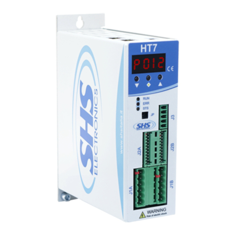
Only HT7xx_PN model is supplied of PROFINET inte face ( uppe ight pictu es )
The p ofiNET connections can be used inte changeably.

www.shsitalia.it info:[email protected]
7
1.6 Protection / Display messages
D ive is p ovided with p otections against ove tempe atu e, ove voltage, unde voltage, sho t-ci cuits among
outputs and among outputs and the positive powe pole, no-phase moto connection.
If one of the mentioned conditions occu s, d ive disables the powe b idge and shows an e o condition on the
display.
To esto e the d ive in the case of the following e o s:
- Ove cu ent
- A Phase moto E o
- B Phase moto E o
You must eset the unit.
The decimal point to the left indicates the status RX, while the one on the ight indicates the status of the
communication inte face TX.
DISPLAY DESCRIPTION
Driv OK at STOP motor
Motor in mov m nt
Driv DISABLE
Ph1o A Phas motor Error
Ph2o B Phas motor Error
R s t phas
rdY
run
dIS
ocur Ov rcurr nt Error
tenP Ov rt mp ratur Error
uuoL Und rvoltag Error
ouoL Ov rvoltag Error
rSt

www.shsitalia.it info:[email protected]
8
1.7 Parameters setting
By using the buttons below the display (he einafte efe ed to as [\/] , [<>], [/\] ) you can pa amete ize the d ive:
●To access to main menù, p ess [\/] + [<>] , it will visualized “menu” fo 1 sec , afte the pa amete “p001”
●F om the main menu to select the pa amete to be changed p ess the button [\/] o [/\].
●F om main menù to visualize the actual value of pa amete p ess [<>].
●F om the pa amete to change the value p ess [\/] o [/\]
●F om the pa amete to sto e the value p ess the button [<>] fo 1 sec and it will appea “memo”
●F om the pa amete to come back at main menù without modify any conditions, p ess [<>] less than 1 sec
(don’t will appea “memo”).
●F om the main menù to go out p ess [<>] + [/\].
NOTE: Fo settings PROFINET pa amete s efe to attach
Legend MODE:
ST = Step/Di ection
WS = RS485 SHS P otocol
MB = Modbus
CO = CanOpen
PARAMETER MODE FUNCTION
p001 ST+WS+MB+CO
p002 ST+WS+MB+CO
p003 ST+WS+MB Curr nt s tting [A]
p004 WS+MB+CO S tting s rial Baud Rat
p005 WS+MB+CO S tting s rial addr ss
p006 ST+WS+MB
p007 ST+WS+MB S tting stand-by curr nt ( 0, 25, 50, 100% )
p008 ST+WS+MB
p009 ST+WS+MB
p010 ST+WS+MB S tting wav mod ( wav0, wav1 )
p011 ST+WS+MB S tting to op rat high fr qu ncy
p012 R s rv d R s rv d param t r for diagnostic
p013 MB
0par : wh n this param t r is stor d, all
param t rs will b s t to d fault valu and it
will app ar “rst” th n r start th driv r.
S t th s rial mod “ser” or st p/Dir ction
“step”, if th mod is chang d, aft r “memo”
will app ar “rst” and th driv will r start
S tting st p r solution ( 1/2, ..., 1/20 )
S tting param t r r sonanc 1 r duction
( fd0, ..., fd4 )
S tting param t r r sonanc 2 r duction
( small, big )
S tting s rial parity ( n, , o )

www.shsitalia.it info:[email protected]
9
1.8 Mechanical dimension
Mod l HT7xx- W ight [ gr ]
WS-MB-CO-PB 655
PN-EC 720

www.shsitalia.it info:[email protected]
10
2. CONNECTIONS
2.1 INSTALLATION NOTES
ATTENTION
DANGER OF ELECTRICAL SHOCK
ONLY QUALIFIED PERSONNEL SHOULD WORK ON THIS EQUIPMENT. DISCONNECT ALL
POWER BEFORE WORKING ON EQUIPMENT. DANGEROUS VOLTAGES MAY EXIST AFTER
POWER IS REMOVED! BEFORE WORKING ON EQUIPMENT CHECK DC BUS VOLTAGE OF
DRIVES EACH TIME POWER IS REMOVED.
The t ansfo me powe is =Vac*(Inf(tot) + 1)
Whe e is VA powe , Vac is seconda y voltage in Volts and Inf(tot) is the sum of all nominal cu ents set in all
the d ive to be supplied.
NOTE: use tr nsformer with n isol ted second ry, don’t connect the second ry t ground.
2.2 AC Power Supply
V c nom, : Range value of voltage by which the d ive can be powe ed.
V c m x: Ope tative Maximum voltage. Ove this limit, the p otection of maximum voltage inhibits the d ive.
V c min: Ope ative Minimum voltage. Unde this limit, the p otection of minimum voltage inhibits the d ive.
I m x: Maximum value of phase cu ent.
I min: Minimum value of phase cu ent.
Oper ting temper ture: Fo any tempe atu e ove 45°C and any cu ent ove 6A a fo ced ventilation is
necessa y.
Vdc ux: Logic powe supply.
(*) Not apply to models PN and EC that equi e only 24Vdc
HT710 HT720 HT730 HT740
[V]
[V] 75 75 75 110
[V] 15 15 15 15
[A] 4 7 12 12
[A] 1 1 1 1
[°C] 0 - 45 0 - 45 0 - 45 0 - 45
[V]
Unit
V c nom
F om 18 to 60 F om 18 to 60 F om 18 to 60 F om 18 to 90
V c m x
V c min
I
m x
I
min
Oper tion
temper ture
Vdc ux(*)
F om 24 to 90 F om 24 to 90 F om 24 to 90 F om 24 to 125

www.shsitalia.it info:[email protected]
11
In AC powe mode do not connect GND signals between two o mo e HT7 d ives:

www.shsitalia.it info:[email protected]
12
2.3 DC POWER SUPPLY
HT710 HT720 HT730 HT740
[V]
[V] 110 110 110 160
[V] 20 20 20 20
[A] 4 7 12 12
[A] 1 1 1 1
[°C] 0 - 45 0 - 45 0 - 45 0 - 45
[V]
Unit
Vdc nom
F om 24 to 90 F om 24 to 90 F om 24 to 90 F om 24 to 125
Vdc m x
Vdc min
I
m x
I
min
Oper ting
temper ture
Vdc ux (*)
F om 24 to 90 F om 24 to 90 F om 24 to 90 F om 24 to 125
Vdc nom, : Range value of voltage by which the d ive can be powe ed.
Vdc m x: Ope ating Maximum voltage. Ove this limit, the p otection of maximum voltage inhibits the d ive.
Vdc min: Ope ating Minimum voltage. Unde this limit, the p otection of minimum voltage inhibits the d ive.
I m x: Maximum value of phase cu ent.
I min: Minimum value of phase cu ent.
Oper ting temper ture: Fo any tempe atu e ove 45°C and any cu ent ove 6A a fo ced ventilation is
necessa y.
Vdc ux: Logic powe supply.
(*) Not apply to models PN and EC that equi e only 24Vdc

www.shsitalia.it info:[email protected]
13
2.4 Inputs / Outputs
(IN1, IN2, IN3, ENABLE) VOLTAGE LEVEL
LOW LEVEL FROM 0 TO 7V
HIGH LEVEL FROM 10 TO 24V
MAX CURRENT 13 mA
TTL SINGLE ENDED 24V
LOW LEVEL FROM 0 TO 2V FROM 0 TO 6V
HIGH LEVEL FROM 4 TO 5V FROM 9 TO 24V
MAX CURRENT
DIFFERENTIAL INPUTS
(ENCAx, ENCBx, ENCZx)
5 mA 13 mA
OUTPUTS VOLTAGE LEVEL
PNP OUT OUT ON COM_OUT VOLTAGE - 2V
OUT OFF 0V
NPN OUT OUT ON 2V
OUT OFF COM_OUT VOLTAGE
ANALOG INPUTS VOLTAGE LEVEL
INPUT FROM 0 TO 10V
OUTPUT FROM 0 TO 10V
Digital inputs and outputs pins a e isolated f om powe .
●Single Ended inputs a e NPN/PNP type selectable th ough COM-IN pin.
●Diffe ential input a e TTL compatible, and can be 24V compatible PNP th ough COM-ENC pin.
●Outputs a e NPN/PNP type selectable th ough COM-OUT (10mA max fo OUT1, 100mA max fo OUT2 and
OUT3). On equest the outputs can be equipped with OptoMOS devices (maximum cu ent 400mA, 60V).
Analog inputs and outputs pins a e not isolated f om powe , they have ange 0 to 10V.
INPUTS FEATURES:

www.shsitalia.it info:[email protected]
16
2.8 Analog Inputs / Outputs
Note: we suggest to use isol ted inputs scheme, no electric l
connections between control nd drives.
2.9 FIELDBUS Interface
The d ives a e supplied with half duplex RS485 and CAN inte face.
The FIELDBUS is isolated f om the powe stage.
To enable diffe ent p otocols must be loaded diffe ent fi mwa e.

www.shsitalia.it info:[email protected]
17
3. OPERATING MODE
3.1 Step/Direction Mode
The d ive can be ope ated in the follwing modes:
●SHS PROTOCOL
●MODBUS
●CANOPEN
To change the use mode use the keyboa d and change the p002 pa amete .
When the ope ating mode is changed, esta t the d ive.
Note: In SHS PROTOCOL and MODBUS mode, the d ive can be use in Step/Di ection mode.
The Inputs and the outputs a e the following
Inputs:
SIGNAL FUNCTION
IN1
(J2A.11)
STEP-IN
Ex cut th st p on th LOW/HIGH transition of this signal.
Us a squar wav with duty-cycl of 50%.
Signal abs nc for 0.5 s conds d t rmin s th automatic curr nt
r duction (stand-by condition).
P rc ntag of r duction in stand-by can b s t to 25% or to 50% of
th r gulat d curr nt through P007.
Max Fr qu ncy 70KHz at Half St p (incr as r solution and
proportionally incr as th max st p in fr qu ncy)
IN2
(J2A-10)
DIRECTION
S l ct th motor rotation wis
Signals must b stabl for at l ast 50 micros conds b for and
50 micros conds aft r th low/high transition of th STEP-IN signal.
IN3
(J2A-9)
CURRENT REDUCTION
It r duc s th motor curr nt.
Th p rc ntag of curr nt r duction can b s t from 0%
to 100% (p007).
ENA/DIS
(J2A-8)
This input can b us d as ENABLE or DISABLE using th DIP1.4
DIP1.4 ON DISABLE: Wh n th input is activat d th motor
will b stopp d.
DIP1.4 OFF ENABLE: Wh n th input is d activat d th motor
will b stopp d.

www.shsitalia.it info:[email protected]
18
Outputs:
SIGNAL FUNCTION
OUT1
(J2B-2)
STEP OUT
Toggl v ry st p-in
OUT2
(J2B-3)
DRIVER-READY
Driv in prot ction: OUT2 OFF
Driv r ady : OUT2 ON
OUT3
(J2B-4)
Unus d

www.shsitalia.it info:[email protected]
19
4. HT7 MODELS CODE
HT7xxKK - yyyyy / Zzz
SPECIAL VERSION:
Dzz = Dedicate Softwa e
Szz = Modify Ha dwa e (*)
OPTION:
View the following table
FIELDBUS:
WS = RS485 SHS P otocol
MB = Modbus
CO = CanOpen
PB = P ofibus
PN = P ofiNet
EC = Ethe Cat
SIZE:
10 = 4A 18..60Vac o 24..90Vdc
20 = 7A 18..60Vac o 24..90Vdc
30 = 12A 18..60Vac o 24..90Vdc
40 = 12A 18..90Vac o 24..125Vdc
The defaul configu ation it:
●Input and encode f om 12 to 24V
●Opto Outputs ( not static elè )
Code
1 (*)
2 (*)
4 Input TTL
8 (*)
16
32 (*)
64
128
256
512 (*)
1024 (*)
2048 (*)
yyyyy OPTION
Diffe ential Encode
Encode TTL
OUT1 PNP OptoRelay
OUT1 NPN/PNP Opto elay
OUT2 PNP OptoRelay
OUT2 NPN/PNP OptoRelay
EEp om special Fi mwa e
Analog Input
Fieldbus c imp connecto
Fieldbus DB9 connecto
IO c imp connecto
(*) not available fo this d ive
EXAMPLE 1: the default configu ation will become option 0 ( 00000 )
EXAMPLE 2: TTL Input + OUT1 NPN/PNP elay + EEp om Fi mwa e, will become option 4+16+128 = 148 ( 00148 )

S.H.S. s.r.l. Via F.lli Rosselli, 29 20027 Rescaldina (MI) – ITALY Tel. +39 0331 466918 Fax. +39 0331 466147 www.shsitalia.it
Other manuals for HT7 Series
2
This manual suits for next models
1
Table of contents
Other SHS DC Drive manuals
Popular DC Drive manuals by other brands
ZF
ZF Duoplan 2K800 operating instructions

Inovance
Inovance MD330H user manual
Hakko Electronics
Hakko Electronics 152B instruction manual
Selve
Selve MAN Rescue Installation and operating instructions
Festo
Festo EMCA-EC-67 CO Series operating instructions
Anaheim Automation
Anaheim Automation MBC25SI1TB user guide


