SHS HT7 Series User manual

S.H.S. s.r.l. Via F.lli Rosselli, 29 20027 Rescaldina (MI) – ITALY Tel. +39 0331 466918 Fax. +39 0331 466147 www.shsitalia.it
User Guide
STEPPING MOTOR DRIVE
Series
HT7
HW MANUAL
HT7_HW_MANUAL_re 9_eng

Safety notes
The SHS automation products should be handled, installed and maintained by qualified personnel trained
on installation of automation components, and only for the purposes described in the user manual
Installers must pay particular attention to the potential risks caused by mechanical and electrical
equipment
It is very important that applications and installations meet all applicable safety requirements.
Each installer has an obligation to take responsibility to verify their knowledge and understanding of all applicable
safety standards.
Any use which does not meet the safety requirements can damage equipment and injure the user
SHS s r l does not consider itself responsible for, and assumes no liability for damage caused by handling
products and / or improperly installed, or in cases where the customer has allowed, or executed,
modifications and / or repairs not authorized by SHS s r l
The SHS drives are devices for automation high performance capable of generating rapid movements and high
forces.
Pay high attention especially during installation and application development.
Only use equipment properly sized for the application..
The SHS devices are considered components for automation and are sold as finished products to be installed only
by qualified personnel and in accordance with all local safety regulations.
The technicians must be able to recognize possible dangers that may result from programming by changing
parameter values and generally by the mechanical electrical and electronic.
SHS s.r.l. recommends to always follow basic safety rules. Failure to heed them can result in injury to persons and /
or property.
General precautions:
This manual is subject to change due to product improvement specification changes or improvements of the
manual
SHS s.r.l. is not responsible for damage to property and/or persons caused by faulty installation and / or
unauthorized modifications of the product.
The damaged drive systems must not be installed or put into operation in order to avoid injury persons
and damage to property. Changes or modifications made to the drive systems is prohibited and It
involves the extinction of any right to warranty or of any obligation of responsibility.
2
www.shsitalia.it info:[email protected]

www.shsitalia.it info:[email protected]
Index
TECHNICAL DATA 4
1.1 Power supply / Motor Connector 4
1.2 FIELDBUS Connector 4
1.3 Input/Output Connectors 5
1.4 DIP-SWITCH and Ethernet Connectors 6
1.5 Status LEDS 6
1.6 Protection / Display messages 7
1.7 Parameters setting 8
1.8 Mechanical dimension 9
CONNECTION 10
2.1 Installation note 10
2.2 AC Power Supply 10
2.3 DC Power Supply 12
2.4 Input / Outputs 13
2.5 Digital Inputs 14
2.6 Digital Outputs 14
2.7 Encoder Inputs 15
2.8 16
OPERATING MODE 16
HT7 MODELS CODE 17
Analog Inputs/ Outputs
3

www.shsitalia.it info:[email protected]
1. TECHNICAL DATA
1.2 FIELDBUS Conne tor
1.1 Power supply / Motor onne tor
J1A ( Left )
SIGNAL FUNCTION
B2 Phase B2 of the motor
B1 Phase B1 of the motor
A2 Phase A2 of the motor
A1 Phase A1 of the motor
HVI Power supply input DC
(connect to HV0 or use as input DC power)
GND 0V power supply
J1B ( Right )
SIGNAL FUNCTION
AC1 Power supply Vac
AC2 Power supply Vac
HV0 Rectified output
AUX Logic power supply input 24Vdc
SHIELD Shield
0S 0V power supply Aux
J3 SIGNAL FUNCTION
1 0V
2 CL (CANL)
3 RS- (RS485-) Used only upgrade firmware
4 CH (CANH)
5 RS+ (RS485+)
4

www.shsitalia.it info:[email protected]
1.3 Input / Output Conne tors
J2A (Left) SIGNAL FUNCTION
1 ENC_AH Encoder A+
2 ENC_AL Encoder A-
3 ENC_BH Encoder B+
4 ENC_BL Encoder B-
5 ENC_ZH Encoder Z+
6 ENC_ZL Encoder Z-
7 ENC_COM Encoder common (don't use in differential
mode)
8 ENA/DIS Input ENABLE/DISABLE
9 IN3 Input IN3 – (CURRENT REDUCTION)
10 IN2 Input IN2 - (DIRECTION)
11 IN1 Input IN1 – (STEP IN)
J2B (Right) SIGNAL FUNCTION
12 OUT_COM Output common (OUT1 OUT2 OUT3)
13 OUT1 Output OUT1 - (default motor run)
14 OUT2 Output OUT2 - (default Drive Ready)
15 OUT3 Output OUT3 - (default unused)
16 IN_COM Input common (IN1 IN2 IN3 ENA/DIS)
17 AN_IN0 Analog Input IN0 (*1)
18 AN_IN1 Analog Input IN1 (*1)
19 AN_IN2 Analog Input IN2 (*1)
20 AN_OUT Analog Output (*1)
21 GND_SIGNAL 0V (relative at EXT_12V AN_IN AN_OUT)
(*1)
22 EXT_12V Output +12V (relative at GND_:SIGNAL)
5
*1: IF YOU NEED TO USE THE ANALOG INPUTS AND OUTPUTS WITH MORE THAN ONE DRIVE POWERED BY THE SAME
TRANSFORMER (ON TERMINALS J1B-AC1 AND J1B-AC2) YOU MUST SWITCH TO DC POWER (ON TERMINALS J1A-HVI AND
J1A_GND) AVOIDING THE USE OF THE INTERNAL RECTIFIER (TERMINALS J1B-AC1, J1B-AC2 AND J1B-HVO DISCONNECTED)

www.shsitalia.it info:[email protected]
1.4 DIP SWITCH
1.5 Status LEDS
DIP1 ON OFF
1 Insert termination CAN Not used
2 Insert termination RS485 Not used
3 Not used Not used
4 Input function En / Dis = ENABLE Input function En / Dis = DISABLE
Phisical
Features Connection Type Cable /
Transmission type Speed Max Cable
Lenght
Electrical RJ45 Connector
100base-TX Shield
cable CAT5 IEEE
802.3
100Mbit/s full
duplex 100 mt
LED FUNCTION
RUN
Drive OK Light ON
Drive Error Light OFF
ERR
Drive Error Light ON
Drive OK Light OFF
STS
Drive OK Light fast blinking
Drive Error Light slow blinking
Only HT7xx PN, EC, EI model is supplied of double RJ45 interface ( upper pictures ).
The RJ45 connections can be used interchangeably in PN and EI model, in the EC model RJ45s ha e IN
and OUT
6

www.shsitalia.it info:[email protected]
1.6 Prote tion / Display messages
DISPLAY DESCRIPTION
rdY Drive OK at STOP motor
run Motor in movement
dIS Drive DISABLE fieldbus
HdIS Drive DISABLE Hardware (1) (2)
ocur Overcurrent Error
tenP Overtemperature Error
uuoL Undervoltage Error
ouoL Overvoltage Error
rSt Reset phase
0net Fieldbus not connected
enc Encoder Fault
Dri e is pro ided with protections against o ertemperature, o er oltage, under oltage, short-circuits among
outputs and among outputs and the positi e power pole, no-phase motor connection.
If one of the mentioned conditions occurs, dri e disables the power bridge and shows an error condition on
the display.
To restore the protection use the fault reset bit in the control word, or restart the dri e.
The decimal point to the left indicates the status RX, while the one on the right indicates the status of the
communication interface TX.
The leds near the RJ45 connectors indicate the fieldbus state (1)
(1) A ailable only in EC, EI, PN release.
(2) If not a ailable “Dri e Disable Hardware” is “DIS” on the display.
7

www.shsitalia.it info:[email protected]
1.7 Parameters setting
PARAMETER FUNCTION MODE
p001
0par: when this parameter is stored all parameters
will be set to default value and it will appear “rst” then
restart the driver
WS MB CO PN EC EI MT
p002 Step-Dir/Fieldbus WS MB CO
p003 Current setting [A] WS MB PN EI MT
p00 BaudRate WS MB CO
p005 Address-ID WS MB CO EC
p006 Setting step resolution ( 1/2 ... 1/20 ) WS MB PN EI MT
p007 Setting stand-by current ( 0 25 50 100% ) WS MB
p008 Setting parameter resonance1 reduction ( fd0...fd4 ) WS MB
p009 Setting parameter resonance2 reduction ( small big ) WS MB
p010 Setting wave mode ( wav0 wav1 ) WS MB
p011 Setting to operate high frequency WS MB
p013 Setting toggle bit ( 0 - 1 ) PN EC EI MT
p01 Enable refresh for the last polled parameter PN EC EI MT
p015 FieldBus Type and Firmware Release WS MB CO PN EC EI MT
By using the buttons below the display (hereinafter referred to as [\/] , [<>], [/\] ) you can parameterize the dri e:
To access to main menù, press [\/] + [<>] , it will isualized “ menu ” for 1 sec, after the parameter “ p001 ”
From the main menu to select the parameter to be changed press the button [\/] or [/\].
From main menù to isualize the actual alue of parameter press [<>].
From the parameter to change the alue press [\/] or [/\]
From the parameter to store the alue press the button [<>] for 1 sec and it will appear “ memo ”
From the parameter to come back at main menù without modify any conditions, press [<>] less than 1 sec (don’t will
appear “ memo”).
From the main menù to go out press [<>] + [/\].
8
WS = RS485 SHS Protocol
MB = Modbus
CO = CanOpen
PB = Profibus
PN = ProfiNet
EC = EtherCat
EI = Ethernet/IP
MT=Modbus/TCP

www.shsitalia.it info:[email protected]
1.8 Me hani al dimension
MODEL HT7 xx- WEIGHT [ gr ]
WS-MB-CO-PB 655
PN-EC-EI 720
9

www.shsitalia.it info:[email protected]
2. CONNECTIONS
2.1 INSTALLATION NOTES
ATTENTION
2.2 AC Power Supply
Unit HT71H HT72H HT73H HT74H
Vac nom [V] From 18 to 60 From 18 to 60 From 18 to 60 From 18 to
100
Vac max [V] 75 75 75 110
Vac min [V] 15 15 15 15
I max [A] 4 7 12 12
I min [A] 1 1 1 1
Operation
Temperature [°C] 0 - 45 0 - 45 0 - 45 0 - 45
Vdc aux [V] 24 24 24 24
Idc aux [A] 0.1 0.1 0.1 0.1
DANGER OF ELECTRICAL SHOCK
ONLY Q ALIFIED PERSONNEL SHO LD WORK ON THIS EQ IPMENT. DISCONNECT ALL POWER
BEFORE WORKING ON EQ IPMENT. DANGERO S VOLTAGES MAY EXIST AFTER POWER IS
REMOVED! BEFORE WORKING ON EQ IPMENT CHECK DC B S VOLTAGE OF
DRIVES EACH TIME POWER IS REMOVED.
The transformer power is =Vac*(Inf(tot) + 1)
Where is VA power, Vac is secondary voltage in Volts and Inf(tot) is the sum of all nominal currents set
in all the dri e to be supplied.
NOTE: use a transformer with an isolated secondary, don’t connect the secondary at ground.
Vac nom : Range alue of oltage by which the dri e can be powered.
Vac max: Opertati e Maximum oltage. O er this limit, the protection of maximum oltage inhibits the dri e.
Vac min: Operati e Minimum oltage. Under this limit, the protection of minimum oltage inhibits the dri e.
I max: Maximum alue of phase current.
I min: Minimum alue of phase current.
Operating temperature: For any temperature o er 45°C and any current o er 6A a forced entilation is
necessary.
Vdc aux: Logic power supply.
Idc aux: Logic power supply maximum current.
10

www.shsitalia.it info:[email protected]
In AC power mode do not connect GND signals between two or more HT7 dri es:
WIRING DIAGRAM:
11

www.shsitalia.it info:[email protected]
2.3 DC POWER SUPPLY
WIRING DIAGRAM:
Unit HT71H HT72H HT73H HT74H
Vdc nom [V] From 24 to 90 From 24 to 90 From 24 to 90 From 24 to 140
Vdc max [V] 110 110 110 160
Vdc min [V] 20 20 20 20
I max [A] 4 7 12 12
I min [A] 1 1 1 1
Operation
Temperature [°C] 0 - 45 0 - 45 0 - 45 0 - 45
Vdc aux [V] 24 24 24 24
Idc aux [A] 0.1 0.1 0.1 0.1
Vdc nom : Range alue of oltage by which the dri e can be powered.
Vdc max: Operating Maximum oltage. O er this limit, the protection of maximum oltage inhibits the dri e.
Vdc min: Operating Minimum oltage. Under this limit, the protection of minimum oltage inhibits the dri e.
I max: Maximum alue of phase current.
I min: Minimum alue of phase current.
Operating temperature: For any temperature o er 45°C and any current o er 6A a forced entilation is
necessary.
Vdc aux: Logic power supply.
Idc aux: Logic power supply maximum current.
12

www.shsitalia.it info:[email protected]
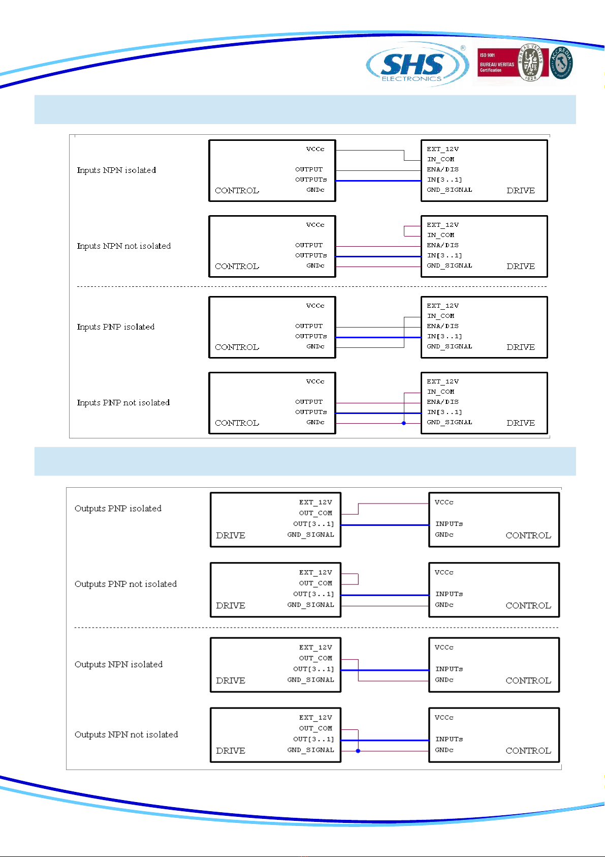
2.4 Inputs / Outputs
INPUTS FEATURES:
ANALOG INPUTS VOLTAGE LEVEL
INPUT FROM 0 TO 10V
OUTPUT FROM 0 TO 10V
(IN1, IN2, IN3, ENABLE) VOLTAGE LEVEL
LOW LEVEL FROM 0 TO 7V
HIGH LEVEL FROM 10 TO 24V
MAX CURRENT 13mA
DIFFERENTIAL INPUTS
(ENCAx, ENCBx, ENCZx) TTL SINGLE ENDED 24V
LOW LEVEL FROM 0 TO 2V FROM 0 TO 6V
HIGH LEVEL FROM 4 TO 5V FROM 9 TO 24V
MAX CURRENT 5mA 13mA
OUTPUTS VOLTAGE LEVEL
PNP OUT
OUT ON COM_OUT VOLTAGE -2V
OUT OFF 0V
NPN OUT
OUT ON 2V
OUT OFF COM_OUT VOLTAGE
Digital inputs and outputs pins are isolated from power.
●Single Ended inputs are NPN/PNP type selectable through COM-IN pin.
●Differential input are TTL compatible, and can be 24V compatible PNP through COM-ENC pin.
●Outputs are NPN/PNP type selectable through COM-OUT (10mA max for OUT1, 100mA max for OUT2 and
OUT3). On request the outputs can be equipped with OptoMOS de ices (maximum current 400mA, 60V).
Analog inputs and outputs pins are not isolated from power, they ha e range 0 to 10V.
13


www.shsitalia.it info:[email protected]
2.8 Analog Inputs / Outputs
Note: we suggest to use isolated inputs scheme, no electrical
connections between control and drives.
3. OPERATING MODE
The dri er can be operated in one of the follwing modes:
●SHS RS485 PROTOCOL (WS)
●MODBUS RTU (MB)
●CAN OPEN (CO)
●PROFIBUS (PB)
●PROFINET (PN)
●ETHERCAT (EC)
●ETHERNET/IP (EI)
●MODBUS/TCP (MT)
16
Refer to the appropriate Fieldbus manual

www.shsitalia.it info:[email protected]
4. HT7 MODELS CODE
HT7XHKKj - yyyyy / zzz
FIELDB S:
WS = RS485 SHS Protocol
MB = Modbus
CO = CanOpen
PB = Profibus
PN = ProfiNet
EC = EtherCat
EI = Ethernet/IP
MT=Modbus/TCP
j= Hardware Fieldbus Release
CODE yyyyOPTION
1 Differential Encoder
2 Encoder TTL
4 Input TTL
8 OUT1 PNP OptoRelay (*)
16 OUT1 NPN/PNP
32 OUT2 PNP OptoRelay (*)
64 OUT2 NPN/PNP
128 EEprom special Firmware
256 Analog Input
512 Fieldbus crimp connector (*)
1024 Fieldbus DB9 connector (*)
2048 IO crimp connector (*)
The defaul configuration it:
●Input from 12 to 24V
(*) not a ailable for this dri e
EXAMPLE 1: the default configuration will become option 0 ( 00000 )
EXAMPLE 2: TTL Input + OUT1 NPN/PNP relay + EEprom Firmware, will become option 4+16+128 = 148 ( 00148 )
OPTION:
View the following table
SIZE:
1 = 4A 18..60Vac or 24..90Vdc
2 = 7A 18..60Vac or 24..90Vdc
3 = 12A 18..60Vac or 24..90Vdc
4 = 12A 18..90Vac or 24..140Vdc
H= MAINBOARD RELEASE
SPECIAL VERSION:
Dzz = Dedicate Software
Szz = Modify Hardware (*)
17
- Lower case coding are optional
- (*) not a ailable for this dri e

www.shsitalia.it info:[email protected]
18

S.H.S. s.r.l. Via F.lli Rosselli, 29 20027 Rescaldina (MI) – ITALY Tel. +39 0331 466918 Fax. +39 0331 466147 www.shsitalia.it
Other manuals for HT7 Series
2
Table of contents
Other SHS DC Drive manuals


Popular DC Drive manuals by other brands

Rockwell Automation
Rockwell Automation Allen-Bradley PowerFlex 7000 user manual

Danfoss
Danfoss VLT Midi Drive FC 280 Programming guide

Phoenix Mecano
Phoenix Mecano Dewert Okin DUOMAT 3 CARE EASY installation instructions

Masterflex
Masterflex 75211-12 operating manual

Toshiba
Toshiba GX7R ASD quick start guide

DEMAG
DEMAG Dedrive Pro ACS880-DEMAG Series Quick start up guide


