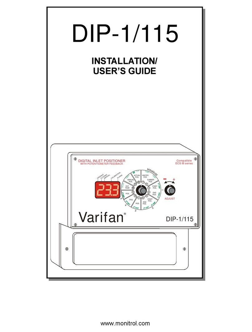
Varifan DIP-1C Operation manual

MANUAL
DIP-1C
Installation / User’s Guide
ATTENTION ELECTRICIAN
SEE WIRING DETAILS ON PAGES A-3 TO A-6 AND
ADDITIONAL INFORMATION IN SECTION B
DIGITAL INLET POSITIONER
with potentiometer feedback
®
Varifan
5
5
DIP-1C
OPENING CLOSING MANUAL
T
E
M
P
.
T
E
MP
.
M
I
N
I
M
U
M
SUMMER
POS.
WINTER
POS.
ACTUAL
POS.
MANUAL
OVERRIDE
VARIABL E
POS.
STAGE
POS.
OUT.
TEMP.
CALIB.
LOW
LIMIT
INLET
PRECI-
SION
ALARM
CODE
11 12 12
3
4
5
7 6
10
9
8
U
N
I
T
2
V
A
R
.
P
O
S
.
S
T
G
.
P
O
S
.
VARI ABLE
POS.
STAGE
POS.
73
USER’S GUIDE INSTALLATION GUIDE
INDEX / WARRANTY WIRING DIAGRAM
www.monitrol.com

DIP-1C WIRING DIAGRAM
Section A-2 DIP-1C
WARNINGS AND PRECAUTIONS
Although the manufacturer has made every effort to ensure the accuracy of the
information contained herein, this document is subject to change without notice due to
ongoing product development.
WARNINGS AND PRECAUTIONS
Equipment, probe failure, blown fuses and/or tripped breakers may prove harmful to the
contents of the building. Therefore it is strongly recommended to install backup devices
and alarm or warning devices. Spare equipment should also be available at the owner’s
site. Equipment manufactured by the manufacturer is protected against normal line
surges. High surges caused by thunderstorms or power supply equipment may damage
this equipment. For added security against line voltage surges it is recommended that
surge and noise suppression devices be installed at the electrical distribution panel. Use
of shielded cable for probes is recommended for protection against lightning. These
devices are available from most electrical supply distributors.
RECOMMENDATIONS
The manufacturer recommends that all installation procedures described herein be
performed by a qualified electrician or installation technician. Furthermore the
manufacturer recommends testing all the functions and equipment connected to the DIP-
1C, including the alarm system and backup devices, after installation, after changes to
the installation and every month after that.
Fuse verification and replacement, as well as the proper setting of control values shall
be the responsibility of the owner of this equipment.
www.monitrol.com

DIP-1C WIRING DIAGRAM
DIP-1C Section A-3
WIRING DIAGRAM
DIP-1C
SECTION A
www.monitrol.com

DIP-1C WIRING DIAGRAM
Section A-4 DIP-1C
Wiring Diagram (115/230VAC inlet)
6
DIP-1C30/05/11 WIR
REV
0
Varifan
R
GND
MGCB
CTL2 ALARM
LINE 115/230V
L2/N
30V/1A
MAX
7
4 5
CLO
COM
OPN
ACTUATOR
GND
MGCB
CTL1
A1
C1
B1
ACT
L1
FEEDBACK
POTENTIOMETER
CLOSE
OPEN
COM
INLET
INLET
115/230 VAC
C
-
+
L1
L2/N
8
8VAC
MGCB
GND
PLS
MODULES
8
8VAC
MGCB
GND
PLS
MODULES
LINE VOLTAGE
SELECTOR
230V
SEE NOTES ON PAGE A-6
WIRING DIAGRAM
WARNING!!!
SET LINE VOLTAGE
TO CORRECT VALUE BEFORE
ATTEMPTING TO OPERATE
THE MODULE.
ECS-xC CONTROLECS-xC CONTROL
WIRING DIAGRAM DIP-1C (115/230VAC )INLET
8
www.monitrol.com

DIP-1C WIRING DIAGRAM
DIP-1C Section A-5
Wiring Diagram (24VDC inlet)
6
DIP-1C30/05/11 WIR
REV
0
Varifan
R
GND
MGCB
CTL2 ALARM
LINE 115/230V
L2/N
30V/1A
MAX
7
4 5
CLO
COM
OPN
ACTUATOR
GND
MGCB
CTL1
A1
C1
B1
ACT
L1
FEEDBACK
POTENTIOMETER
(-)
(+)
INLET
INLET
24 VDC
C
-
+
ECS-xC CONTROL
8
8VAC
MGCB
GND
PLS
MODULES
ECS-xC CONTROL
8
8VAC
MGCB
GND
PLS
MODULES
LINE VOLTAGE
SELECTOR
230V
TRANSFORMER
+24V
GND
-24V
SEE NOTES ON PAGE A-6
EXTERNAL
±24 VOLTS
POWER
SUPPLY
WIRING DIAGRAM
WIRING DIAGRAM DIP-1C (24VDC )INLET
WARNING!!!
SET LINE VOLTAGE
TO CORRECT VALUE BEFORE
ATTEMPTING TO OPERATE
THE MODULE.
8
www.monitrol.com

DIP-1C WIRING DIAGRAM
Section A-6 DIP-1C
DIP-1C
Electrician’s notes
(COMMUNICATION WIRING) SHIELDED LOW CAPACITANCE WIRE,
(Capacitance between conductors @ 1Khz = 24pF/ft), TWISTED PAIR (8
twist/ft), AWG #22, 820ft (250m) MAX LENGTH. (Ex.: BELDEN 8761)
HIGH VOLTAGE WIRE INSTALLED ACCORDING TO LOCAL WIRING
CODE.
INSTALL LOW VOLTAGE WIRES (POTENTIOMETER OR COMPUTER LINK
WIRES) AT LEAST 12in. (30cm) AWAY FROM HIGH VOLTAGE WIRES
(120/230VAC, 24VDC). ALWAYS CROSS HIGH AND LOW VOLTAGE WIRES
AT A 90-DEGREE ANGLE.
RELAYS: 10A @ 240VAC RESISTIVE, MOTOR 1HP @ 240VAC, 1/2HP @
120VAC AT EACH OUTPUT.
MAXIMUM 2 WIRES OF SAME SIZE PER BLACK TERMINAL, NO BIGGER
THAN AWG #12, NO SMALLER THAN AWG #22.
1 WIRE ONLY PER GREEN TERMINAL. USE WIRE CONNECTOR IF YOU
WANT TO CONNECT MORE THAN 1 WIRE, NO BIGGER THAN AWG #12,
NO SMALLER THAN AWG #28.
CHECK INSTALLATION GUIDE FOR ALARM WIRING.
USE SHIELD FOR SHIELDING PURPOSE ONLY. CONNECT THE SHIELD TO
GROUND PLATE . NEVER LEAVE THE SHIELD UNCONNECTED AT BOTH
ENDS. NEVER CONNECT BOTH ENDS OF THE SHIELD TO GROUND
PLATE . THE USE OF A SHIELD FOR POTENTIOMETER AND ALL
COMMUNICATION WIRE IS MANDATORY.
1
5
7
8
4
1
2
3
6
www.monitrol.com

DIP-1C INSTALLATION
DIP-1C Section B-7
INSTALLATION
DIP-1C
SECTION B
www.monitrol.com

DIP-1C INSTALLATION
Section B-8 DIP-1C
This section will inform the electrician on proper wiring and installation
procedures for the DIP-1C.
The manufacturer recommends that the following installation instructions to be
followed as closely as possible, and that all work be performed by a certified
electrician. Failure to do so may void the warranty.
Unpacking
Unpack the DIP-1C and inspect contents for damage. Should the contents
appear to be damaged, contact your local distributor to return the equipment.
The package should contain the following standard items:
1 DIP-1C Module
4 Brackets / 4 Screws
1 Installation / User’s Guide
Mounting Hardware Required
This is the list of the mounting hardware needed, which is not included with the
product:
Shielded two-wire twisted pair cable, AWG #22 (used for communication) see
electrician note for capacitance selection.
4 screws (to hang the unit onto the wall).
Screwdrivers.
Soldering iron kit or approved sealed connectors.
Drill and hole saw kit
www.monitrol.com

DIP-1C INSTALLATION
DIP-1C Section B-9
General installation guidelines
DIP-1C Module
-It is recommended to install the unit in a hallway to limit the DIP-1C exposure
to noxious gases.
-In order to avoid condensation problems inside the module, it is
recommended to install the DIP-1C on an inside wall. If it is not possible, use
spacers to have an air gap between the wall and the DIP-1C.
-It is required to install the DIP-1C side up with the cable entry holes facing
down.
-The enclosure is watertight, but do not spray water or immerse the DIP-1C in
water. Cover it carefully with plastic when cleaning the room.
-The DIP-1C should be installed in easy access location but away from
damaging elements (heat, cold, water, direct sunlight, …).
-Do not drill the face, the side, the top or the rear of the module.
-Do not install the DIP-1C near high voltage equipment, power supply or
transformer.
Electrical Cables
-All electrical cables must be installed according to local wiring codes.
-All cable shields must be connected to the DIP-1C power ground only, except
for the cable connected to the optional PC interface and to the ventilation
controllers. The shield is needed to protect the DIP-1C and the modules
against any electromagnetic interference generated by lightning or nearby
operating machinery.
-Never use the shield as a conductor.
-Connect only one end of the shield to the ground of the DIP-1C.
-Use separate conduit for the low voltage cables (communication) and the high
voltage cables. There must be at least 1 foot (30 cm) between low voltage
and high voltage conduits.
-If a low-voltage cable has to cross over a high voltage cable, make this
crossing at 90°.
-All cable connections must be soldered or done with approved sealed
connectors.
-Communication cables must be 820’ (250m) or less.
-It is prohibited to use overhead cables outside the building.
www.monitrol.com

DIP-1C INSTALLATION
Section B-10 DIP-1C
Electrical Power
-Protection from electrical surge should be included in the planning of each
installation.
-It is strongly recommended to have a backup power source to ensure life-
sustaining conditions in case of power failure (see figure 2).
-The backup system and alarm must be thoroughly tested and verified as
working properly before using the ventilation system.
Mounting
-The enclosure must be mounted in a location that will allow the cover to be
completely opened right up against the wall.
-Fasten the four brackets to the four mounting holes on the back of the
enclosure, using the four screws provided with the brackets.
-Then mount the enclosure on the wall by inserting screws through the
brackets’ adjustment slots, into the wall. Make sure to position the enclosure
so that all wires extend out of the bottom section of the enclosure.
-The bracket slots also serve to adjust the position of the module.
-Once you have adjusted the module position, tighten the four mounting
screws.
FIGURE NO. 1 Mounting Position and Devices
www.monitrol.com

DIP-1C INSTALLATION
DIP-1C Section B-11
Connection Procedure
Detailed Wiring Diagrams
Typical Power Backup Wiring
A backup relay (DPDT) connects to the power source 1 in normal operation but
will switch to the power source 2 if source 1 is disabled. The backup relay should
be selected to ensure it is able to support the required power load.
FIGURE NO. 2 Typical Power Backup Wiring
8 PIN RELAY DPDT
(OMRON model MK2EP-UA-AC120)
3
4
5
6
2
1
8
7
NO 2
NO 1
NC 1
NC 2
COM 2
COM 1
L2 GND
L1
3
4
5
6
2
1
8
7
L2 L1 GND
source 1
DISTRIBUTION
PANEL
L2 L1
N
LINE
230 VAC
source 2
DISTRIBUTION
PANEL
LINE
230 VAC
www.monitrol.com

DIP-1C INSTALLATION
Section B-12 DIP-1C
Typical Alarm Connection Wiring
The DIP-1C provides a normally closed dry contact to set off an alarm
(potentiometer problem, power loss or other malfunctions). It may be connected
to an alarm system or directly to a siren and /or auto-dialer.
The relay will activate 6-8 seconds after an alarm is triggered.
FIGURE NO. 3 Typical Alarm Connection Wiring
ALARM SYSTEM /
AUTO DIALER
GND
MGCB
GND
MGCB
CTL2 ALARM
30V/1A
MAX
X1340
DIP-1C
C1
B1
A1
ACT CTL1
www.monitrol.com

DIP-1C INSTALLATION
DIP-1C Section B-13
Powering Up Procedure
Once the DIP-1C is properly mounted on the wall and all controllers connected to
the terminal block, perform the following step:
Verify all Connections
Seal all cable entry holes.
Hermetically Close the DIP-1C
Close the front panel.
Put the power on
Secure the front panel with a lock
Downloading the Configuration
When upgrading your system with a new configuration, you will have to download
the configuration.
There are two ways to download a configuration in the DIP-1C.
1) Downloading by powering down.
A. Ensure the power source of the DIP-1C is OFF (flip the circuit breaker on
the distribution panel).
B. Remove the faceplate screws and lift up the cover.
C. Insert the configuration chip (MMX) into the socket of the main board.
D. Switch on the power source. The display on the front panel should indicate
dNLD for approximately 15 seconds. If dNLD is not displayed, try one
more time. If dNLD is still not displayed, remove and replace the
configuration chip (MMX).
E. When the downloading procedure is complete, remove the configuration
chip (MMX) and place it in the bottom part of the enclosure or in another
safe location. Once the MMX Chip is removed, the DIP-1C starts up and
executes the configuration.
2) Downloading while the DIP-1C is powered up.
A. Remove the faceplate screws and lift up the cover.
B. Place the MMX chip into the socket of the main board. At this moment, the
MMX Detected parameter will appear.
C. Adjust the MMX Detected parameter to dNLD and press the SET/CLR
button. The display on the front panel should indicate dNLD for
www.monitrol.com

DIP-1C INSTALLATION
Section B-14 DIP-1C
approximately 15 seconds. If dNLD is not displayed, try one more time. If
dNLD is still not displayed, remove and replace the configuration chip
(MMX).
D. When the downloading procedure is complete, remove the configuration
chip (MMX) and place it in the bottom part of the enclosure or in another
safe location. Once the MMX Chip is removed, the DIP-1C starts up and
executes the configuration.
Note: During this procedure, some components are live and can be
dangerous if touched.
Uploading the Configuration
It is possible to upload a configuration into a configuration chip (MMX) in order to
save parameters and setup or to backup the configuration.
Here’s the procedure to upload a configuration.
A. Make sure that the DIP-1C is powered up.
B. Remove the faceplate screws and lift up the cover.
C. Place the MMX chip into the socket of the main board. At this moment, the
MMX Detected parameter will appear.
D. Adjust the MMX Detected parameter to upLD and press the SET/CLR
button. The display on the front panel should indicate upLD for
approximately 15 seconds. If upLD is not displayed, try one more time. If
upLD is still not displayed, remove and replace the configuration chip
(MMX).
E. When the uploading procedure is complete, remove the configuration chip
(MMX) and place it in the bottom part of the enclosure or in another safe
location. Once the MMX Chip is removed, the DIP-1C will continue to
execute the configuration.
WARNING: During this procedure, some components are live and can
be dangerous if touched.
www.monitrol.com

DIP-1C INSTALLATION
DIP-1C Section B-15
DIP-1C Compatible Modules
This is the list of all compatible modules that can be connected with DIP-1C with
a short description of their function.
Computer interface
NET-IN2 Communication Module (Module inserted into the DIP-1C to
communicate with the computer interface)
RF-IN Communication Module (Module inserted into the DIP-1C for a
wireless communication with the computer interface)
www.monitrol.com

DIP-1C INSTALLATION
Section B-16 DIP-1C
Specifications
Storage temperature -4°F to 131°F (-20°C to 55°C)
Operating temperature 32°F to 113°F (0°C to 45°C)
Humidity 90% maximum Non-condensing
Weight 2,4 lb (1,1 kg)
Size 9” x 7” x 4 3/4” (22.8 cm x 17.7 cm x 11.5 cm)
Protection index IP 66
Warranty 2 years
POWER SUPPLY (LINE 230V)
Operational voltage range 184 to 250VAC
Operational frequency range 45 to 65 Hz
Power supply circuit consumption (CPU
Board) 12 VA
ACT INPUT (Inlet Potentiometer)
Maximum wire length 500 feet (150 m)
Recommended wires 2 conductors, stranded, AWG #22
Potentiometer 0-10K ohms
ALARM RELAY
Maximum current 1 A at 30VDC
Delay before activation Between 6 and 8 seconds
OUTPUT RELAYS
Maximum Current 1HP @ 240VAC, 1/2HP @ 120VAC, 10A @
240VAC
Caution Notice These relays are rated by UL and CSA at 1HP
@ 240VAC, 1/2HP @ 120VAC. However, it is
recommended not to use more than 1/2HP @
240VAC, 1/4HP @ 120VAC per relay.
COMMUNICATIONS PORT (MGCB)
Maximum wire length (19200 bps) 6.5 feet (2 m)
Recommended wire 2 strands, twisted pair, low capacity, shielded,
AWG #22
Important Notice:
-It is important to have a backup system in case of a system failure.
-Low-voltage and high-voltage wire must be passed through different
conducts at least 1 foot (30 cm) apart. If low-voltage and high-voltage
conduits must be crossed, the crossing must be at a 90-degree angle.
- All wiring must be made by a certified electrician and conform to local
electrical regulations.
www.monitrol.com

DIP-1C INSTALLATION
DIP-1C Section B-17
Troubleshooting
SYMPTOM CAUSE REMEDY
Display is blank DIP-1C is not powered.
Flat cable between the
main and top boards of the
DIP-1Cis disconnected.
Make sure the control is
powered.
Make sure the fuse is
correct.
Make sure the flat cable is
connected.
www.monitrol.com

DIP-1C USER’S GUIDE
Section C-18 DIP-1C
USER’S GUIDE
DIP-1C
SECTION C
www.monitrol.com

DIP-1C USER’S GUIDE
DIP-1C Section C-19
DIGITAL INLET POSITIONER
with potentiometer feedback
®
Varifan
5
5
DIP-1C
OPENING CLOSING MANUAL
T
E
M
P
.
T
E
MP
.
M
I
N
I
M
U
M
SUMMER
POS.
WINTER
POS.
ACTUAL
POS.
MANUAL
OVERRIDE
VARIABL E
POS.
STAGE
POS.
OUT.
TEMP.
CALIB.
LOW
LIMIT
INLET
PRECI-
SION
ALARM
CODE
11 12 12
3
4
5
7 6
10
9
8
U
N
I
T
2
V
A
R
.
P
O
S
.
S
T
G
.
P
O
S
.
VARI ABLE
POS.
STAGE
POS.
73
Module Description
[
5
]
[
1
]
[
3
]
[
4
]
[
6
]
[
2
]
www.monitrol.com

DIP-1C USER’S GUIDE
Section C-20 DIP-1C
1. Output LED
Those LED indicate the status of an output. A LED comes ON whenever the
respective output is active.
2. LED Status Windows
The LED status window features a 5 digit LED readout display. After a setting is
selected, its value appears on the LED display. If the value is flashing, it can be
changed with the value setting buttons ( and ).
3. Parameter Dial
This button is used to select parameters or parameter groups.
4. Value Setting Button
This button is used to increase or decrease the value on the LED window. Turn it
clockwise to increase the value. Turn it counter clockwise to decrease the value.
5. F2 Button
This button is used to access to secondary function of a parameter group
(appears in green around the parameter dial).
6. SET/CLR Button
This button is used to acknowledge a function, set a value (high and low inlet
limits).
www.monitrol.com
Table of contents
Other Varifan Control System manuals

Varifan
Varifan VPM-1 User manual

Varifan
Varifan MVS-1C User manual

Varifan
Varifan CPS-3M User manual

Varifan
Varifan ECS-2M User manual

Varifan
Varifan CM10-2 User manual

Varifan
Varifan MST-2B User manual

Varifan
Varifan ECS 5M User manual

Varifan
Varifan IC-68ND User manual

Varifan
Varifan CPS-2C Operation manual

Varifan
Varifan SVIM-1LE User manual