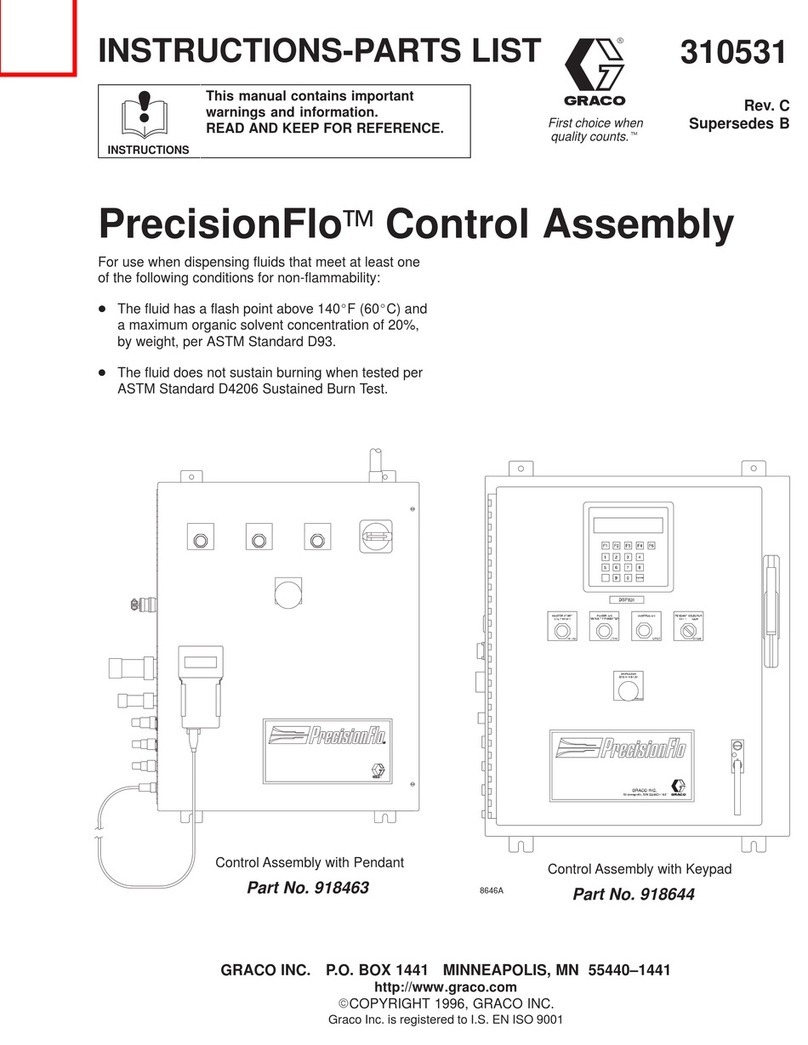
Graco ProMix 239735 Operation manual

308783
Rev. C
Supersedes B
First choice when
quality counts.
Certified to CAN/CSA
22.2 No. E79–11–95
Conforms to ANSI/UL
standard 2279
Recognized Component
EExia II A T4
98D.123384
Intrinsically Safe for Hazardous Locations
Class I; Division 1; Group D*
*If an external power supply is connected to the control, the control
is no longer intrinsically safe and the control, as well as the power
supply, must not be operated in hazardous locations.
If a printer is connected to the control, Printer Barrier Kit 240652
must be installed to maintain intrinsic safety. If the printer is
installed without the Printer Barrier Kit, the control is no longer
intrinsically safe and the control and printer must not be installed
or operated in hazardous locations.
D
7486A
INSTRUCTIONS-PARTS LIST
INSTRUCTIONS
This manual contains important
warnings and information.
READ AND KEEP FOR REFERENCE.
ProMixControl Assembly
For proportional mixing of plural component coatings
3000 psi (21 MPa, 207 bar) Maximum Working Fluid Pressure
4000 psi (28 MPa, 276 bar) Maximum Fluid Working Pressure with Part No. 239954 High Pressure Spring Kit
3000 psi (21 MPa, 207 bar) Maximum Solvent Supply Pressure
100 psi (0.7 MPa, 7 bar) Maximum Working Air Pressure
Part No. 239735
GRACO INC. P.O. BOX 1441 MINNEAPOLIS, MN 55440–1441
COPYRIGHT 1997, GRACO INC.
Graco Inc. is registered to I.S. EN ISO 9001
Parts
Contents

2 308783
Symbols
Warning Symbol
WARNING
This symbol alerts you to the possibility of serious
injury or death if you do not follow the instructions.
Caution Symbol
CAUTION
This symbol alerts you to the possibility of damage to
or destruction of equipment if you do not follow the
instructions.
Table of Contents
Symbols 2. . . . . . . . . . . . . . . . . . . . . . . . . . . . . . . . . . . . . .
Warnings 3. . . . . . . . . . . . . . . . . . . . . . . . . . . . . . . . . . . . .
Icons 5. . . . . . . . . . . . . . . . . . . . . . . . . . . . . . . . . . . . . . . . .
Product Icons 5. . . . . . . . . . . . . . . . . . . . . . . . . . . . . . . . . .
Operation Mode Icons 6. . . . . . . . . . . . . . . . . . . . . . . . . .
Setup Mode Icons 6. . . . . . . . . . . . . . . . . . . . . . . . . . . . . .
ProMix Proportioner Overview 8. . . . . . . . . . . . . . . . .
Installation 9. . . . . . . . . . . . . . . . . . . . . . . . . . . . . . . . . . .
Location 9. . . . . . . . . . . . . . . . . . . . . . . . . . . . . . . . . . . . . . .
Fluid Supply 9. . . . . . . . . . . . . . . . . . . . . . . . . . . . . . . . . . .
Setup 10. . . . . . . . . . . . . . . . . . . . . . . . . . . . . . . . . . . . . . . .
Operator Controls 14. . . . . . . . . . . . . . . . . . . . . . . . . . . .
Operator Station 14. . . . . . . . . . . . . . . . . . . . . . . . . . . . . .
Keypad 14. . . . . . . . . . . . . . . . . . . . . . . . . . . . . . . . . . . . . .
Operation Mode 14. . . . . . . . . . . . . . . . . . . . . . . . . . . . . . .
Setup Mode 15. . . . . . . . . . . . . . . . . . . . . . . . . . . . . . . . . .
Reference Card 15. . . . . . . . . . . . . . . . . . . . . . . . . . . . . . .
Adjusting Setup Values 16. . . . . . . . . . . . . . . . . . . . . . . . .
Pressure Relief Procedure 17. . . . . . . . . . . . . . . . . . . .
Startup 18. . . . . . . . . . . . . . . . . . . . . . . . . . . . . . . . . . . . . .
Reporting 21. . . . . . . . . . . . . . . . . . . . . . . . . . . . . . . . . . . .
Shutdown 21. . . . . . . . . . . . . . . . . . . . . . . . . . . . . . . . . . .
Purging 22. . . . . . . . . . . . . . . . . . . . . . . . . . . . . . . . . . . . .
Purging the ProMix of Mixed Material 22. . . . . . . . . . . .
Purging the Fluid Supply 23. . . . . . . . . . . . . . . . . . . . . . .
Ratio Check 25. . . . . . . . . . . . . . . . . . . . . . . . . . . . . . . . .
Alarm Troubleshooting 28. . . . . . . . . . . . . . . . . . . . . . .
To Clear the Alarm and Restart the System 28. . . . . . .
Off Ratio Alarm 28. . . . . . . . . . . . . . . . . . . . . . . . . . . . . . .
Dose Time of Component A or B Exceeded 29. . . . . . .
Overdose A or Overdose B 29. . . . . . . . . . . . . . . . . . . . .
Idle Time Exceeded 30. . . . . . . . . . . . . . . . . . . . . . . . . . . .
Pot Life Exceeded 30. . . . . . . . . . . . . . . . . . . . . . . . . . . . .
Service 31. . . . . . . . . . . . . . . . . . . . . . . . . . . . . . . . . . . . . .
Instruction Manuals 31. . . . . . . . . . . . . . . . . . . . . . . . . . . .
Hardware or Software Updates 31. . . . . . . . . . . . . . . . . .
Blinking Display 32. . . . . . . . . . . . . . . . . . . . . . . . . . . . . . .
Replacing the Circuit Board or Keypad 32. . . . . . . . . . .
Replacing the Solenoids 33. . . . . . . . . . . . . . . . . . . . . . . .
Removing and Installing the Meters 34. . . . . . . . . . . . . .
Removing and Installing the Mix Manifold 35. . . . . . . . .
Power Supply Turbine Alternator Service 36. . . . . . . . .
Accessories 37. . . . . . . . . . . . . . . . . . . . . . . . . . . . . . . . .
Parts 38. . . . . . . . . . . . . . . . . . . . . . . . . . . . . . . . . . . . . . . .
Dimensions 42. . . . . . . . . . . . . . . . . . . . . . . . . . . . . . . . . .
Technical Data 43. . . . . . . . . . . . . . . . . . . . . . . . . . . . . . .
Graco Standard Warranty 44. . . . . . . . . . . . . . . . . . . . .
Graco Phone Number 44. . . . . . . . . . . . . . . . . . . . . . . .

308783 3
WARNING
INJECTION HAZARD
Spray from the gun, hose leaks, or ruptured components can inject fluid into your body and cause
extremely serious injury, including the need for amputation. Splashing fluid in the eyes or on the skin
can also cause serious injury.
Fluid injected into the skin might look like just a cut, but it is a serious injury. Get immediate medi-
cal attention.
Do not point the spray gun at anyone or at any part of the body.
Do not put hand or fingers over the spray tip.
Do not stop or deflect fluid leaks with your hand, body, glove, or rag.
Follow the Pressure Relief Procedure on page 17 whenever you: are instructed to relieve pres-
sure; stop spraying; clean, check, or service the equipment; or install or clean the spray tip.
Tighten all the fluid connections before operating the equipment.
Check the hoses, tubes, and couplings daily. Replace worn, damaged, or loose parts immediately.
Permanently coupled hoses cannot be repaired; replace the entire hose.
FIRE, EXPLOSION, AND ELECTRIC SHOCK HAZARD
Improper grounding, poor air ventilation, open flames, or sparks can cause a hazardous condition and
result in fire or explosion and serious injury.
Ground the equipment and the object being sprayed. See “Ground the System”on page 13.
The ProMix control is intrinsically safe when used without any external electrical components
connected to it. If an external power supply or printer is connected to the control, the control is no
longer intrinsically safe and the control, as well as the power supply and printer, must not be oper-
ated in hazardous locations, as defined in article 500 of the National Electrical Code (USA) or your
local electrical code.
If using an external power supply, do not exceed the +24 volts maximum applied voltage. Discon-
nect electrical power at the main switch before servicing the equipment.
Turn off the air to the air driven power supply before servicing the equipment.
Provide fresh air ventilation to avoid the buildup of flammable vapors from solvent or the fluid being
sprayed.
Extinguish all the open flames or pilot lights in the spray area.
Keep the spray area free of debris, including solvent, rags, and gasoline.
Do not turn on or off any light switch in the spray area while operating or if fumes are present.
Do not smoke in the spray area.
Do not operate a gasoline engine in the spray area.
If there is any static sparking while using the equipment, stop spraying immediately. Identify and
correct the problem.
Keep liquids away from the electrical components.
Continued on the next page.

4 308783
WARNING
INSTRUCTIONS
EQUIPMENT MISUSE HAZARD
Equipment misuse can cause the equipment to rupture, malfunction, or start unexpectedly and result
in serious injury.
This equipment is for professional use only.
Read all instruction manuals, tags, and labels before operating the equipment.
Use the equipment only for its intended purpose. If you are uncertain about usage, call your Graco
distributor.
Do not alter or modify this equipment. Use only genuine Graco parts and accessories.
Check the equipment daily. Repair or replace worn or damaged parts immediately.
Do not exceed the maximum working pressure of the system components. See the instruction
manuals of the individual system components for their maximum working pressures. The ProMix
control has a 3000 psi (21 MPa, 207 bar) maximum working fluid pressure or 4000 psi (28
MPa, 276 bar) maximum working fluid pressure with kit 239954 installed and 100 psi (0.7
MPa, 7 bar) maximum working air pressure.
The solvent supply line inside the control has a 3000 psi (21 MPa, 207 bar) maximum working
fluid pressure. The fluid supply for solvent purging must not exceed this maximum working pres-
sure.
Route the hoses away from the traffic areas, sharp edges, moving parts, and hot surfaces. Do not
expose Graco hoses to temperatures above 180F (82C) or below –40F (–40C).
Use only Graco approved hoses. Do not remove hose spring guards, which help protect the hose
from rupture caused by kinks or bends near the couplings.
Do not use the hoses to pull the equipment.
Use fluids or solvents that are compatible with the equipment wetted parts. See the Technical
Data section of all the equipment manuals. Read the fluid and solvent manufacturer’s warnings.
Comply with all applicable local, state and national fire, electrical and other safety regulations.
TOXIC FLUID HAZARD
Hazardous fluids or toxic fumes can cause serious injury or death if splashed in the eyes or on the
skin, swallowed, or inhaled.
Know the specific hazards of the fluid you are using. Read the fluid manufacturer’s warnings.
Store hazardous fluid in an approved container. Dispose of hazardous fluid according to all local,
state and national guidelines.
Wear the appropriate protective clothing, gloves, eyewear, and respirator.

308783 5
Icons
Product Icons
Control Assembly
The following icons are on the outside of the control
case. They indicate air, fluid, and cable connections.
See the Installation section for more information.
Component A fluid line connection
Component B fluid line connection
Solvent fluid line connection
Ground wire connection
Air line connection
Gun air outlet
Air signal outlet
Alarm air outlet
External power connector
Printer cable connector
Operator station connector
Operator Station
The following icons are on the front of the operator
station. They indicate the three operation modes (mix
standby, and purge) and the report function. See page
14 for more information.
Mix
Standby
Purge
Report

6 308783
Icons
Operation Mode Icons
The system is in Operation Mode when it is powered
up. The operations that are commonly used in every-
day operation appear as icons on the keypad. These
icons include:
TARGET RATIO: Press to display the
ratio that the ProMix Proportioner has
been setup to produce.
ACTUAL RATIO: Press to display the
actual ratio the ProMix is producing.
TOLERANCE: Press to display the ratio
tolerance that the ProMix Proportioner is
currently producing.
COMPONENT A: Press to display the
amount of component A that has been
dispensed since the last time the report
button on the operator station was
pressed. Amount will be in gallons or
liters, depending on how system was
setup.
COMPONENT B: Press to display the
amount of component B that has been
dispensed since the last time the report
button on the operator station was
pressed. Amount will be in gallons or
liters, depending on how system was
setup.
POT LIFE TIME: Press to display the pot
life time remaining in minutes.
Note: Pot life is the approximate length of
time mixed fluid can remain in the system
and stay at its normal viscosity. The time
length is entered during setup.
FLOW RATE: Press to display the cur-
rent flow rate the system is producing in
cc per minute.
Setup Mode Icons
Read page 15 for information on the Reference Card
and how to use it to select setup functions, which are
represented by the following icons.
When a key for a function is pressed, the light below
that function will turn green and the last known value
for that function will display.
Adjust the displayed values using the up and down
arrow keys (no) .
RETURN: The system enters setup at
level 1. Press the return arrow to direct
the control to the next level of setup,
which is level 2; then level 3; then back to
level 1.
Level 1 Icons
SOLVENT VALVE: Hold down the key to
open the solvent valve to clean the ratio
check valves after a ratio check. The
valve closes when the key is released.
TARGET RATIO: Press to adjust the
desired ratio. Can be set from 0.6:1 to
20.0:1.
LITER/GALLON: Press to set value to
liters or gallons for totalizer display val-
ues.

308783 7
Icons
Setup Mode Icons
Level 1 Icons (continued)
TOLERANCE: Press to adjust the ratio
tolerance. If the system operates outside
the tolerance, an alarm will occur.
FLOW METER A CALIBRATION: Hold
down the key for two seconds to initiate a
flow meter ratio check/calibration proce-
dure, which enables the user to see and
adjust the amount of component A dis-
pensed during that procedure. Amount is
displayed in cc.
FLOW METER B CALIBRATION: Hold
down the key for two seconds to initiate a
flow meter ratio check/calibration proce-
dure, which enables the user to see and
adjust the amount of component B dis-
pensed during that procedure. Amount is
displayed in cc.
POT LIFE TIME: Press to adjust the pot
life time in minutes.
Level 2 Icons
HOUR: Press to adjust the hour setting of
the clock.
MINUTE: Press to adjust the minute
setting of the clock.
DAY: Press to adjust the day setting of
the clock.
MONTH: Press to adjust the month set-
ting of the clock.
YEAR: Press to adjust the year setting of
the clock.
PURGE TIME: Press to adjust the purge
time in seconds. The default purge time is
62 seconds. Shots of air and solvent
alternate during the purge time.
Level 3 Icons
OPEN COMPONENT A VALVE: Hold
down the key to open the component A
valve. The valve closes when the key is
released. Used for manual purging and
color change.
OPEN COMPONENT B VALVE: Hold
down the key to open the component B
valve. The valve closes when the key is
released. Used for manual purging and
color change.
POT LIFE VOLUME: Press to adjust the
volume of mixed fluid that must pass
through the system before the pot life
timer resets. The value should represent
the amount of mixed fluid in cubic centi-
meters (cc) that could be in the integrator
(50 cc), static mixer, hoses, and gun.
IDLE TIME: Press to adjust the idle time
in minutes. The idle time sets how long
the operator switch can be set to mix
without any meter pulses before the
dispense valves will close.
OPERATE/SIMULATE: Press to change
to OPERATE or SIMULATE function.
OPERATE is the default setting and
should be selected for normal operation.
SIMULATE is only used for demonstration
or training purposes.
SOFTWARE REVISION: Press to display
the current software revision installed in
the control.

8 308783
ProMix Proportioner Overview
Fig. 1
C
E
67
63d
D
77
F
G
H
J
51
A
B
S
K
L
M
N
O
7487A
I
KEY
A Component A Line
B Component B Line
C ProMix Control
D LED Display
E Component A Supply
F Component B Supply
G Solvent Supply
H Air Regulator
I Fluid Filter , 100 mesh minimum
J Shut-off Valve
K Gun Air Line
L Operator Station Cable
M Gun Fluid Line
N Main Air Line
O Spray Gun
S Solvent Line
51 Air Filter
63d Keypad
67 Mix Manifold
77 Operator Station

308783 9
Installation
NOTE:
Reference numbers and letters in parentheses in
this text refer to the numbers and letters in the
illustrations.
Icons in the text refer to the icons on the equip-
ment, keypad, or reference card.
Fig. 1 shows a typical installation. It is not an actual
system design. To design your system, contact
your Graco representative.
Be sure all accessories are adequately sized and
pressure-rated to meet the system requirements.
For maintenance and safety, you must have a ball
valve between each fluid supply line and the ProMix
system.
A 100 mesh fluid minimum fluid filter (I) must be
installed on the component A and component B
fluid supply lines. See Fig. 1.
See page 42 for dimensions.
CAUTION
The ProMix pot life timer will not function properly
when used with multiple guns that are operating
simultaneously. To avoid having mixed material set in
the equipment, carefully monitor the pot life by some
other means.
Location
WARNING
FIRE AND EXPLOSION HAZARD
The ProMix control is intrinsically safe
when used without any external electri-
cal components connected to it. If an
external power supply or printer is
connected to the control, the control is
no longer intrinsically safe and the
control, as well as the power supply and printer,
must not be operated in hazardous locations, as
defined in article 500 of the National Electrical
Code (USA) or your local electrical code.
The Typical Installation shown in Fig. 1 is only a guide-
line for selecting and installing system components
and accessories, and is not an actual system design.
Follow the installation schematic in the system binder
provided by Graco or contact your Graco representa-
tive for assistance.
Fluid Supply
The following installation and operation instructions
generally presume the system is using pressure tanks
to supply the paint components and solvent. The
Optional Fluid Supplies listed below are two possible
variations and their effect on the instructions.
Optional Fluid Supplies
The fluid supply must be free of pressure spikes, which
are commonly caused by a pump stroke changeover.
If necessary, install pressure regulators or a surge tank
on the fluid inlets to the ProMix, to reduce the fluid
supply pulsation. Contact your Graco representative
for information on fluid pressure regulators.
Supplying Fluid Through Circulating Lines
If there is a central paint recirculating line in your shop,
the ProMix can be connected to it instead of to pres-
sure tanks. Other than references to the pressure
tanks, operation is the same as described in this
manual.
Supplying Fluid Through Pail or Drum Pumps
Instead of pressure tanks, the ProMix can be supplied
by pail or drum pumps. Operation is the same, other
than references to the pressure tanks.

10 308783
Installation
Setup
1. Tighten the fluid line connections between the flow
meter, mix manifold, and other system compo-
nents as they may have loosened during shipment.
2. Mount the ProMix control (C). See Fig. 2. Make
sure the mounting surface can support the weight
of the control and any hoses and accessories
connected to it and any stress that may be applied
during operation.
3. Install the beaker tray (58) with the two screws,
and place the beakers (61) in the tray.
C
KEY
C ProMix Control
58 Beaker Tray
61 Beaker 61
A
F
D
E
C
B
58
Dimensions, inches (mm)
A B C D E F
14.6
(370.8)
24
(609.6)
16
(406.4)
16
(406.4)
10
(254)
4.5
(114.3)
Fig. 2 7488A
4. Screw the air filter (51) into the purge air inlet .
See Fig. 3.
5. Install a shut-off valve (J-1) into the air filter (51) to
shut off the air to the mix manifold.
6. Install a shut-off valve (J-2) into the control air
inlet to shut off the air to the control.
7. Connect two separate air lines to the two control
air inlets.
a. Connect an air line to the shut-off valve (J-1).
NOTE: This line supplies the air for the mix man-
ifold solvent/air purge sequence.
Fig. 3
KEY
A Component A Inlet
B Component B Inlet
S Solvent Inlet
Control Air Inlet (top)
Purge Air Inlet (bottom)
J-1 Shut-off Valve for
Purge Air
J-2 Shut-off Valve for Con-
trol Air
51 Air Filter
J-2
J-1
51
7489A

308783 11
Installation
b. Connect an air line to the shut-off valve (J-2).
NOTE: This line supplies the air to the control
solenoids and air driven power supply and to the
spray gun.
WARNING
COMPONENT RUPTURE HAZARD
To avoid component rupture and serious
injury, including injection, do not exceed
the maximum working pressure of the
system components.
The ProMix control has a 3000 psi (21 MPa,
207 bar) maximum working fluid pressure or
4000 psi (28 MPa, 276 bar) maximum working
fluid pressure with kit 239954 installed and 100
psi (0.7 MPa, 7 bar) maximum working air
pressure.
The solvent supply line inside the control has a
3000 psi (21 MPa, 207 bar) maximum working
fluid pressure. The fluid supply for solvent
purging must not exceed this maximum working
pressure.
8. Connect the fluid supply lines to the ProMix control
connectors. See Fig. 1 and 3.
a. Connect the component A (resin) line from the
fluid supply to control connector A.
b. Connect the component B (catalyst) line from
the fluid supply to control connector B.
c. Connect the solvent line from the fluid supply
to control connector S.
9. Connect fluid and air supply lines to the spray gun.
See Fig. 1 and 4.
a. Connect the gun fluid supply line (M) between
the manifold’s static mixer outlet (P) and the
gun fluid inlet.
Fig. 4
KEY
Gun Air Outlet
Air Signal Outlet (optional)
Alarm Air Outlet (optional)
Operator Station Connec-
tor
Printer Cable Connector
External Power Connector
P Manifold Static Mixer Out-
let
7472A
P

12 308783
Installation
b. Connect the gun air supply line (K) between
the ProMix gun air outlet and the gun air
inlet.
NOTE: Install an air shut off valve in the gun air
supply line or at the gun air inlet.
WARNING
FIRE AND EXPLOSION HAZARD
To reduce the risk of fire and explosion,
an automatic shutoff valve must be
properly installed in the gun air line if using a Graco
electrostatic PROGun.
Contact your Graco representative for information
on air shutoff valves for electrostatic applications.
10. Plug the operator station (77) into the connec-
tor on the ProMix control, using the 50 ft. cable
supplied. See Fig. 1 and 4.
Mount the operator station in an area where the
operator can easily access it.
WARNING
FIRE AND EXPLOSION HAZARD
The ProMix control is intrinsically safe
when used without any external electri-
cal components connected to it. If an
external power supply or printer is
connected to the control, the control is
no longer intrinsically safe and the
control, as well as the power supply and printer,
must not be operated in hazardous locations, as
defined in article 500 of the National Electrical
Code (USA) or your local electrical code.
11. If using a printer, plug the printer cable into the
printer cable connector on the ProMix control.
See Fig. 4.
12. If the external power option is used instead of the
air driven power supply (74) inside the control,
disconnect the wire harness from the power supply
connector (74b). See Fig. 5.
Plug the power cable into the external power
connector . See Fig. 4, page 11. Use a 12–18
Vdc, 0.3 amp power supply. Do not exceed the
+24 volts maximum applied voltage.
13. If the alarm option is used, connect an air line
between the alarm air outlet on the control and
the air inlet on the alarm. See Fig. 4.
Fig. 5
74
74b
7682A

308783 13
Installation
14. Ground the system. See Fig. 6.
WARNING
FIRE, EXPLOSION, AND ELECTRIC
SHOCK HAZARD
To reduce the risk of fire, explosion, or
electric shock, the system must be
properly grounded. Follow the Fire,
Explosion, and Electric Shock Hazard
warnings on page 3 and follow the
instructions below.
a. Connect the ground wire (R) supplied to the
ProMix control ground lug (Q). See Fig. 6.
Connect the ground wire clamp to a true earth
ground as defined in your local code.
b. Ground the other system components (includ-
ing fluid supply units and spray gun) as
instructed in their separate instruction manu-
als.
c. Use only grounded air and fluid hoses.
d. Ground the fluid supply container according to
your local code.
e. Ground the object being sprayed according to
your local code.
f. Ground the solvent pails according to your
local code. Use only metal pails, which are
conductive, placed on a grounded surface. Do
not place the pail on a nonconductive surface,
such as paper or cardboard, which interrupts
the grounding continuity.
g. Maintain grounding continuity when purging or
relieving pressure. Follow the instructions in
your separate gun manual for safely grounding
your gun while purging.
15. Check grounding continuity.
Have a qualified electrician check the resistance
between each ProMix component and the true
earth ground. The resistance must be less than 25
ohms. If the resistance is greater than 25 ohms, a
different ground site may be required. Do not
operate the system until the problem is corrected.
Fig. 6
KEY
Q Ground Lug
R Ground Wire
Q
R
7491A

14 308783
Operator Controls
Two devices provide operator interface; they are the
Operator Station, located in the spray booth, and the
Keypad, located on the control.
Operator Station
The Operator Station consists of an Operator Switch
and a Report Button.See Fig. 7.
Operator Switch
There are three operator switch input settings: mix,
standby, and purge.
Mix
Set the operator switch to mix to start normal operation
(mixing and dispensing) of the system.
Standby
Set the operator switch to standby to stop the system.
Purge
Set the operator switch to purge the system. The
solenoid outputs signal the system to cycle between
the air and solvent purge valves.
NOTE: Purge will not start until two seconds after the
operator switch has been moved to the purge position.
This two second delay allows time to turn the switch to
clear an alarm; see Clearing Alarms, below.
Clearing Alarms
All alarms, except the Pot Life Alarm, can be cleared
by moving the operator switch from mix to standby to
purge to standby. See page 28 for information on
alarms. Turn to mix to resume operation after clearing
the alarm.
Report Button
If a printer is connected to the control, press the report
button to generate a report from the printer. This also
clears the A and B totalizer.
Fig. 7
Report
Button
Operator
Switch
Operator Station 7475A
Keypad
The keypad has a six digit display, eight LED indica-
tors, eight keys to operate and set up the control, and
an up and down arrow to adjust values during setup.
See Fig. 8.
Operation Mode
The system is in Operation Mode when it is powered
up. The functions that are commonly used in everyday
operation appear as icons on the keypad. The mean-
ing of each operation icon is described in Operation
Mode Icons, page 6.
Fig. 8
Display
Up/Down
Arrows
Key LED Indicator
Keypad

308783 15
Setup Mode
The Setup Mode is accessed by turning the operator
switch to Standby and touching the token on the back
of the Reference Card to the setup contacts on the
ProMix control. See Fig. 9.
S
KEY
S Token
Fig. 9 7479A
7475A
There are three levels of setup. The active setup level
number will appear in the left most digit position on the
control display. Level 1 appears when setup is initially
accessed. See Fig. 10.
The first setup function at level 1 is Target Ratio, so
the LED under that icon will be green and the last
known target ratio will be displayed. At startup, that
would be 1.0:1.
Fig. 10
Target Ratio
Setup Level
Icon
Keypad
Reference Card
The Setup Mode icons, which represent setup options,
are on the Reference Card provided. See Fig. 11. The
meaning of each setup icon is described in Setup
Mode Icons on page 6.
The icons are lined up horizontally according to the
setup level where their function is available. They are
lined up vertically with the corresponding Operation
Mode icons, which are the icons seen on the keypad.
The return key 〈↵) moves the system to the next setup
level.
Operation Icons
(on keypad)
Setup Icons
Level 1
Level 2
Level 3
Fig. 11
Reference Card

16 308783
Setup Mode
Adjusting Setup Values
In setup mode, the operator may adjust the values
using the up and down arrow keys (no).
Example:
An operator wanting to change the purge time would
take the following steps.
1. Make sure the operator switch is set
at standby.
7475
A
2. Touch the token to the setup contacts. 1 appears
on the display, indicating the control is at level 1
setup. The last known target ratio will also display.
Target RatioSetup Level
3. Refer to the reference card.
4. Press the return key 〈↵) to move to level 2 setup.
The return key is the key under the icon on the
keypad.
5. 2 appears on the display, indicating that the sys-
tem is at level 2 setup. The first setup function at
level 2 is for setting the Hour, so the last known
hour will be displayed.
Hour
Setup Level
6. Press the purge time icon .
This is the key under the icon on the keypad.
The light under the icon will turn green to indicate
that function has been activated and the last
known purge time setting will display.
NOTE: The purge time displays in seconds and up
to three digits can be entered. The default purge
time is 62 seconds.
Purge TimeSetup Level
7. Press the arrow keys (no) up or down to change
the purge time until the desired value is displayed.
NOTE: If you were changing or checking more
than one setup function, you could press the key
for another function, adjust the value, and continue
to change setup functions until you are finished
and ready to return to operation.
8. Touch the token to the setup contacts to save the
new value.
9. The control will retain the new value and return to
operation mode.
10. Turn the operator switch to mix to begin spraying
again.

308783 17
Pressure Relief Procedure
WARNING
INJECTION HAZARD
The system pressure must be manually
relieved to prevent the system from
starting or spraying accidentally. Fluid
under high pressure can be injected through the
skin and cause serious injury. To reduce the risk of
an injury from injection, splashing fluid, or moving
parts, follow the Pressure Relief Procedure
whenever you:
are instructed to relieve the pressure,
stop spraying,
check or service any of the system equipment,
install or clean the spray tip.
1. Set the operator switch to standby .
2. Shut off the control purge
air (J-1).
J-1
7511
A
Air Shutoff Valve
3. Shut off the air at the spray gun.
4. Relieve fluid and air pressure at the component
and solvent feed pumps or pressure pots, as
explained in their separate instruction manuals.
5. Set the operator switch to mix .
6. Hold a metal part of the
spray gun firmly to the side
of a grounded metal pail,
and trigger the gun to
relieve fluid pressure.
ÄÄÄ
ÄÄÄ
7. Set the operator switch to standby .
8. If you suspect that the spray tip or hose is com-
pletely clogged or that pressure has not been fully
relieved after following the steps above, very
slowly loosen the hose end coupling and relieve
pressure gradually, then loosen the coupling
completely. Now clear the tip or hose obstruction.

18 308783
Startup
CAUTION
The ProMix pot life timer will not function properly
when used with multiple guns that are operating
simultaneously. To avoid having mixed material set in
the equipment, carefully monitor the pot life by some
other means.
NOTE: If the ratio is set to 0.6:1 to 20:1, the ratio will
remain at its setting when powered off and on. If the
ratio is set to 0.5:1 or less and the system is powered
off and on, the ratio will reset to the default of 1:1. All
other settings will also reset to their default.
1. Make sure the operator switch is set
at standby to avoid mixing or purging
material at startup.
7475A
2. Check that the supply containers for component A
and B and solvent are filled.
3. Check that the mix manifold fluid shut-off knobs,
dispense valve knobs, and purge valve knobs are
set as follows:
(T) Fluid Shut-off Knobs: fully open
(U) Dispense Valve Knobs: three “clicks”open
from fully closed setting
(V) Purge Valve Knobs: two turns open from fully
closed setting
(W) Ratio Check Valve Knobs: fully closed
7384B
U
V
T
Reference
T
W
4. Turn the control air supply
on (J-1, J-2).
A diagnostic test will run
and the last known Target
Ratio will display on the
LED panel. This will be a
1.0:1 ratio on the initial
startup. J-1
J-2
7492A
Target Ratio
5. If this is the first startup of the system, purge it as
instructed in Purging the Fluid Supply on page
22. The system was tested with light-weight oil,
which should be flushed out to avoid contaminating
the fluid you will spray.
6. You can check the tolerance, pot life time, and
other operation status information by pressing the
proper key on the keypad. See Operation Mode
Icons on page 6.
7. Setup the ratio and other values as needed. See
Setup Mode,page 15, for setup information.
8. Make sure the operator switch is set
at standby.
7475A

308783 19
Startup
9. Check that the component A and B fluid supply
pressure (X) is properly set for your application. Do
not exceed the controller’s 3000 psi (21 MPa, 207
bar) maximum working fluid pressure or 4000 psi
(28 MPa, 276 bar) maximum working fluid pres-
sure with kit 239954 installed.
X
03096A
Y03096A
10. Check that the fluid valves
(Y) are open.
Air Shutoff Valve
11. Shut off the air at the spray gun.
12. Prime the system.
CAUTION
Do not use the first 4 to 5 oz. (120 to 150 ml) of
material from the system, as it may not be thor-
oughly mixed due to alarms while priming the sys-
tem.
NOTE: If the flow meters overrun because of air in the
system, operation will stop. See Alarm Troubleshoot-
ing on page 28.
a. Touch the token (on the back of the reference
card) to the setup contacts (Z). Number 1
appears on the display, indicating the control is
at level 1 setup.
Z
Setup Level
b. Refer to the reference card, and press the
return key 〈↵) on the keypad twice to move to
level 3 setup.
c. 3 appears on the display, indicating that the
system is at level 3 setup, and the light under
the first icon lights up.
d. Refer to the reference card and
hold down the component A valve
key to open the component A
valve.
ÄÄÄ
ÄÄÄ
e. Trigger the gun into
a grounded waste
container until com-
ponent A flows from
the gun.

20 308783
Startup
f. Release the component A valve key to
close the valve.
g. Hold down the component B
valve key to open the component
B valve. Trigger the gun into a
grounded waste container until
component B flows from the gun.
h. Release the component B valve key to
close the valve.
13. Clear the lines of unmixed material by purging with
solvent.
a. Press the return key 〈↵) to move to level 1
setup.
X
b. Adjust the solvent
fluid supply pressure
(X). Use the lowest
pressure possible to
avoid splashing.
c. Hold down the solvent valve key to open
the solvent valve.
d. Trigger the gun into a grounded waste con-
tainer until solvent flows from the nozzle.
e. Release the solvent valve key to close the
valve.
f. Touch the token to the setup contacts to exit
setup mode.
14. Prime the lines with mixed material.
a. Turn the operator switch to mix.
7476A
b. Trigger the gun into a grounded waste con-
tainer until mixed material flows from the
nozzle.
c. Turn the operator switch to
standby.
7475A
Table of contents
Other Graco Control System manuals
Popular Control System manuals by other brands

Compool
Compool CP3000 Installation & operating instructions

RKC INSTRUMENT
RKC INSTRUMENT FAREX SR MINI SYSTEM Communication instruction manual

Monitech
Monitech ML121QT1400 install guide

elsner elektronik
elsner elektronik WS1000 Style manual

ARCBRO
ARCBRO F2000 Tube Series user manual

Siemens
Siemens DMS8000 Connectivity guide

CAME
CAME G5000 Installation, operation and maintenance manual

Laguna Tools
Laguna Tools SmartShop Maker owner's manual

Carlin
Carlin EZ-Temp 90200 datasheet

Honeywell
Honeywell Tradeline H1008D installation instructions

Joyonway
Joyonway PB554 Simplified operation instruction

Gardena
Gardena 19032 Operator's manual