Rinnai MSB-C3 User manual

Rinnai New Zealand Limited
0800 746 624
2011 MECS: MSB-C1, C2 and C3
01-11
1
Manifold Electronic Control System (MECS)
Innity units can be manifolded together (up to 25) by connecting them in parallel to enable
a greater hot water ow rate than is possible with a single unit. MECS is a totally integrated
system unique to Rinnai that links each Innity unit in the system and will turn on each unit as
required.
The system is designed to ensure gas is not wasted and that an endless supply of hot water is
always available.
How it works
A master and sub-communication PCB is installed in the rst unit and other subsequent units
have only the sub-communication PCB (slave cable) installed. The master communication PCB
receives information about ow rates from the PCB of each unit and balances the load on each
unit. Random selection of the units required to supply the ow demand means that all units
share the workload evenly.
All information is transmitted via communication cables to the slave units. The master control
also had an inbuilt fault detection system and will allocate a replacement unit should one fail.
MSB-C1, C2 and C3
This MECS system has the capability of joining up to 25 Innity units and will replace the
previous Rinnai REU-SA2M/2S and REU-SA3M/3S MECS systems.
Description
Part number Instruction book Description
REU-MSBM MSB-C1 MESC master board for internal mounting inside Innity to connect ve
units
REU-MSBMB MSB-C1 MECS master board for external mounting to connect ve units
REU-MSBC1 MSB-C1 Slave cable to connect one additional unit
REU-MSBC2 MSB-C2 Joiner cable to daisy chain two MECS master boards together (up to a
maximum of ve boards can be connected)
REU-MSBC3 MSB-C3 Slave cable as a spare part for the older REU-MSA2S MECS system
MECS
MSB-C1, MSB-C2,
MSB-C3

Rinnai New Zealand Limited
0800 746 624
2011 MECS: MSB-C1, C2 and C3
01-11
2
MECS
MSB-C1, MSB-C2,
MSB-C3
What to use where
Older MECS system New installs substitute Replacement spare part
REU-MSA2M REU-MSBM REUMSBM
REU-MSA2S REU-MSBC1 REUMSBC3
REU-MSA3M REU-MSBMB REUMSBMB
REU-MSA3S REU-SBC1 REUMSBC1
Decription Master Slave Joiner
Location Inside Innity1External box2
Part number REU-MSBM REU-MSBMB REU-MSBC1 REU-MSBC2
No. of water heaters
2 1 1 - -
3 1 1 1 -
41 1 2 -
5 1 1 3 -
62 2 2 1
72 2 3 1
82 2 41
92 2 5 1
10 2 2 61
11 3 3 5 2
12 3 3 62
13 3 3 72
14 3 3 82
15 3 3 92
16 4 4 8 3
17 4 4 9 3
18 4 4 10 3
19 4 4 11 3
20 4 4 12 3
21 5 5 11 4
22 5 5 12 4
23 5 5 13 4
24 5 5 14 4
25 5 5 15 4
1 Refer Innity model compatibility on next page

Rinnai New Zealand Limited
0800 746 624
2011 MECS: MSB-C1, C2 and C3
01-11
3
MECS
MSB-C1, MSB-C2,
MSB-C3
Innity model compability
Current model Previous model
HD200 REU-VRM2632WC -
HD200i REU-VR2632FFU REU-VM2632FFUG
HD250 REU-VR3237WC REU-VM3237WC
HD250i REU-VM3237FFUC
XR26i REU-V2632FFUG
XR32 REU-V3237WG
HD250E REU-K3237WC
HD250Ei REU-3237FFUC
2 Can be used for all above models, and MUST be used for all HD200 (REU-VM2630WC),
XR & VT domestic models3 and Eciency24 (REU-K2430)
3 Reduced warranty applies to domestic models used in commercial applications

Kit Components
MSB-M (Pack A)
(For wiring Units 1 and 2)
Parts List
Part Qty
Control Board
Communication Cable A
Communication Cable B
Cable tie bracket 2
Cable tie 2
Instruction Sheet 1
MSB-C1 (Pack B)
(For wiring Units 3, 4 and 5)
Parts List
Part Qty
Communication Cable B
Cable tie bracket 2
Cable tie 2
Instruction Sheet 1
Note: One MSB-C1 is required
for each water heater (Units 3, 4,
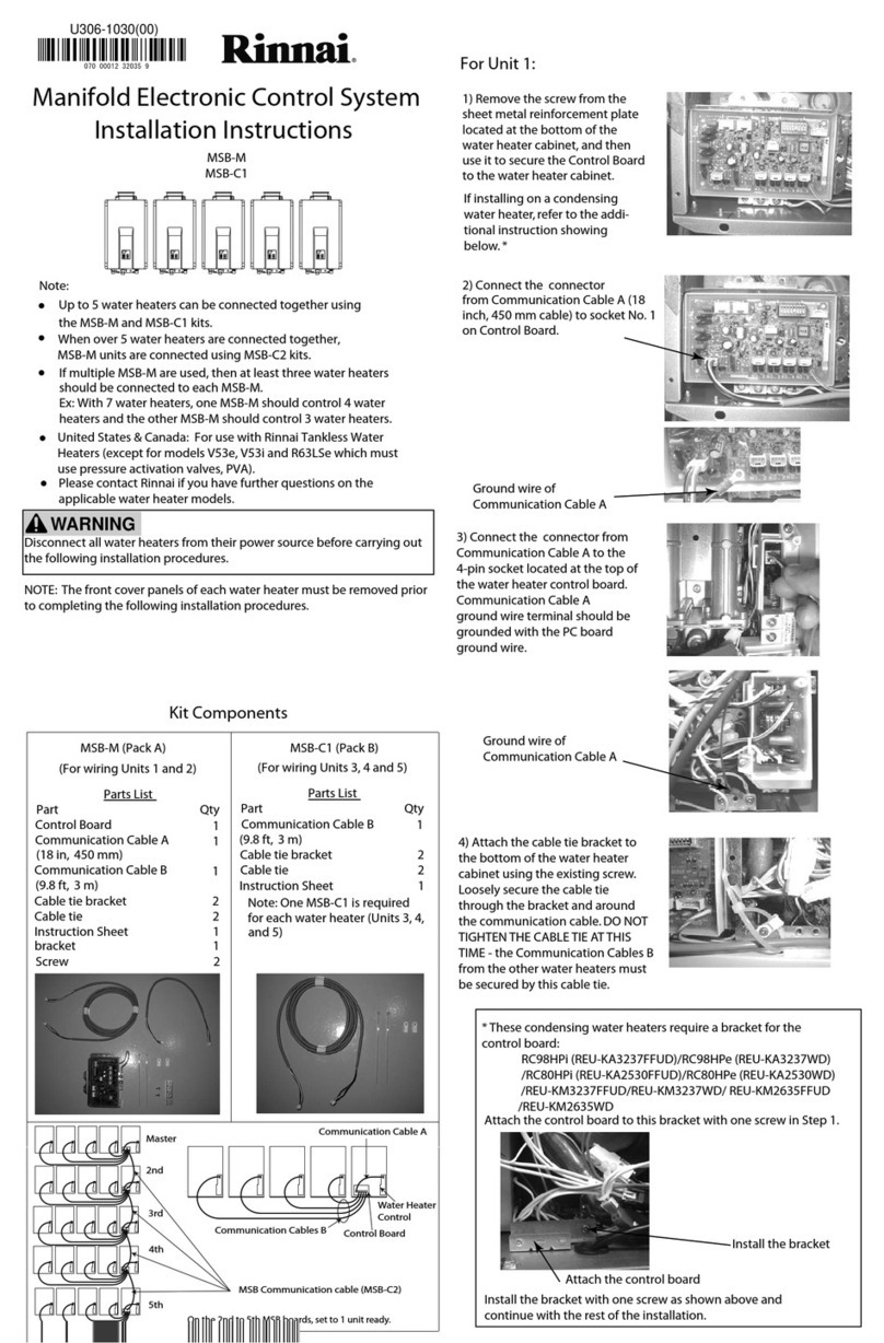
For Unit 1:
1) Remove the screw from the
sheet metal reinforcement plate
located at the bottom of the
water heater cabinet, and then
use it to secure the Control Board
to the water heater cabinet.
2) Connect the connector
from Communication Cable A (18
inch, 450 mm cable) to socket No. 1
on Control Board.
1
1
1
1
and 5)
3) Connect the connector from
Communication Cable A to the
4-pin socket located at the top of
the water heater control board.
Communication Cable A
ground wire terminal should be
grounded with the PC board
ground wire.
4) Attach the cable tie bracket to
the bottom of the water heater
cabinet using the existing screw.
Loosely secure the cable tie
through the bracket and around
the communication cable. DO NOT
TIGHTEN THE CABLE TIE AT THIS
TIME - the Communication Cables B
from the other water heaters must
be secured by this cable tie.
Communication Cables B
Water Heater
Control
Communication Cable A
Control Board
MSB Communication cable (MSB-C2)
bracket 1
If installing on a condensing
water heater, refer to the addi-
tional instruction showing
below. *
(18 in, 450 mm)
(9.8 ft, 3 m)
(9.8 ft, 3 m)
Screw 2
U306-1030(00)
Manifold Electronic Control System
Installation Instructions
MSB-M
MSB-C1
Note:
• Up to 5 water heaters can be connected together using
the MSB-M and MSB-C1 kits.
United States & Canada: For use with Rinnai Tankless Water
Heaters (except for models V53e, V53i and R63LSe which must
use pressure activation valves, PVA).
•
Disconnect all water heaters from their power source before carrying out
the following installation procedures.
NOTE: The front cover panels of each water heater must be removed prior
to completing the following installation procedures.
WARNING
Please contact Rinnai if you have further questions on the
applicable water heater models.
•
• When over 5 water heaters are connected together,
MSB-M units are connected using MSB-C2 kits.
•
Master
2nd
3rd
4th
5th
070 00012 32035 9
* These condensing water heaters require a bracket for the
control board:
RC98HPi (REU-KA3237FFUD)/RC98HPe (REU-KA3237WD)
/RC80HPi (REU-KA2530FFUD)/RC80HPe (REU-KA2530WD)
/REU-KM3237FFUD/REU-KM3237WD/ REU-KM2635FFUD
/REU-KM2635WD
Install the bracket with one screw as shown above and
continue with the rest of the installation.
Install the bracket
Attach the control board
Attach the control board to this bracket with one screw in Step 1.
Ground wire of
Communication Cable A
Ground wire of
Communication Cable A
If multiple MSB-M are used, then at least three water heaters
should be connected to each MSB-M.
Ex: With 7 water heaters, one MSB-M should control 4 water
heaters and the other MSB-M should control 3 water heaters.
On the 2nd to 5th MSB boards, set to 1 unit ready.

For Units 2, 3, 4, and 5:
5) Run the 4-pin connector of
Communication Cable B (9.8 ft, 3 m
cable) up through the cable
access in the bottom of
Unit 1’s cabinet.
8) Connect the 4-pin connector
from Communication Cable B to the
4-pin socket located at the top of
the water heater control board of
9) Attach the cable tie bracket to
the bottom of the water heater
cabinet using the existing screw.
Pull all of the excess cable up into
Unit 2’s cabinet, and then secure it
tightly to the bracket using the
cable tie.
10) Repeat steps 5 to 9 for Units 3,
4, and 5, as applicable.
Note: Communication Cable B for
Unit 3 plugs into socket 3, Unit 4
plugs into socket 4, etc.
11) After making all of the
connections to the Control Board,
tighten all of the cable ties used to
secure the Communication Cables.
12) Place the front cover panels
back on each of the water heaters
using (4) screws.
13) Restore power to the water
heaters.
6) Connect the connector of the
Communication Cable B to socket
2 on the Control Board. The
Communication Cable B ground
wire terminals should be grounded
with the MSB ground wire and
Communication Cable A ground
wire terminal.
• The Control Board can
electronically connect up to 25
water heaters.
• When multiple water heaters
are operating, they will attempt
to supply equal amounts of hot
water.
• On initial water ow demand,
from 1 to 3 units which can be
determined by Dip SW setting
of Master MSB board will open
their servos valves until ow
demand is determined. See
Dip SW table for open water
ow valve. Only the necessary
number of water heaters will
begin to re to meet demand.
Water heaters not ring will
close their valves.
• As the default setting, 3 units will
open its servo valve until ow
demand is determined.
• When installation is completed,
do a test run for all units.
• The temperature setting for all
of the connected water heaters
is controlled by the
temperature controller
connected to the water heater
with the Master MSB Board.
Temperature controllers
connected to the other units
will provide maintenance
codes for their respective units.
• If water heaters do not use a
temperature controller, the
temperature setting for the
water heater with the Master
MSB board is used.
• If a water temperature over
140 degree F is desired, then
an MCC-91 controller needs to
be connected to Master
Control Board.
• For proper operation, it is not
recommended that dierent
models be connected together.
• The order in which each water
heater operates is occasionally
rotated to ensure equal usage
among the entire system.
System Operation
7) Run the other end of
Communication Cable B through
the cable access in the bottom of
Unit 2’s cabinet.
Water ow servo valve is open when water
heater is in standby or working.
An error is detected. A temperature controller
must be connected to this unit to read the
error code.
No unit detected at this connection.
Solid
Flashing Slowly (1.2
sec on / 0.5 sec o)
Flashing Quickly
(0.5 sec on / 0.5 sec
o)
O
EXPLANATION
Water ow servo valve is closed when water
heater is not operating.
Unit 2. Communication Cable B
ground wire terminal should be
grounded with the PC board
ground wire.
Indicator lights on the Control Board indicate the status of each
of the water heaters as follows:
LED 1 ~ 5
NOTE: In a recirculation system, in order to increase the tempera-
ture setting, it is necessary to turn off the power supply to the
circulation pump, increase the temperature setting, and then turn
the pump back on. No additional action is necessary when
decreasing the temperature setting.
3 units ready (default) 2 units ready 1 unit ready
Dip SW
setting
No1 OFF
No2 OFF
No1 ON
No2 OFF
No1 ON
No2 ON
LED 1 ~ 5
LED 6
(Working with multiple MSB boards)
Ground wires of
Communication Cable B
Ground wire of
Communication Cable B
• After the test run, check and clean
the water lter on all units.
Combining dierent models may
result in lower performance.
It is recommended that the dip
switch settings on MSB boards
other than the Master MSB board
be set for 1 unit ready.
•
Dip SW table for open water ow servo valve
When viewing the installed MSB board, the dip switch will be as
shown below (upside down).

Kit Components
MSB-C2 (Pack C)
(For wiring MSB units)
Parts List
Part Qty
MSB Communication cable
Terminal connector 2
Instruction Sheet 1
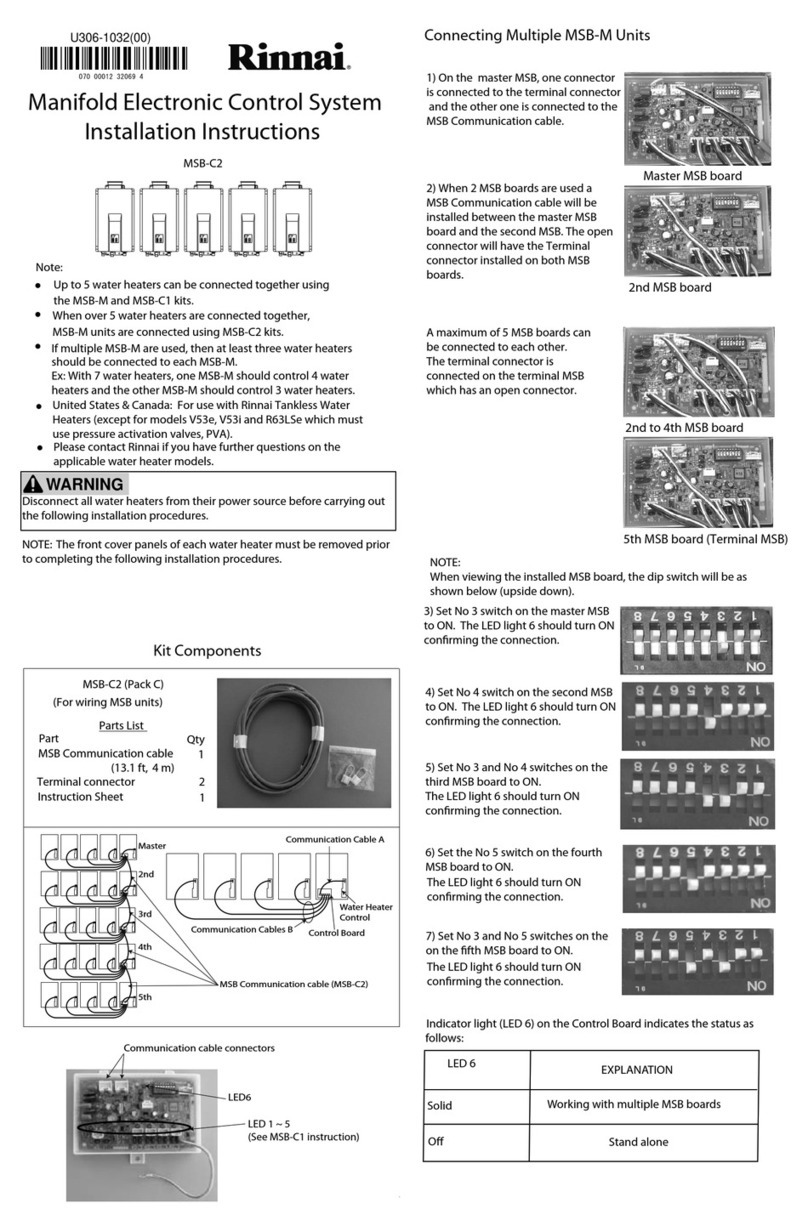
Connecting Multiple MSB-M Units
1) On the master MSB, one connector
is connected to the terminal connector
and the other one is connected to the
MSB Communication cable.
2) When 2 MSB boards are used a
MSB Communication cable will be
installed between the master MSB
board and the second MSB. The open
connector will have the Terminal
connector installed on both MSB
boards.
A maximum of 5 MSB boards can
be connected to each other.
The terminal connection is
connected on the terminal MSB
which has an open connector.
1
3) Set No 3 switch on the master MSB
to ON. The LED light 6 should turn ON
conrming the connection.
Communication Cables B
Water Heater
Control
Communication Cable A
Control Board
MSB Communication cable (MSB-C2)
(13.1 ft, 4 m)
U306-1032(00)
5) Set No 3 and No 4 switches on the
third MSB board to ON.
The LED light 6 should turn ON
conrming the connection.
6) Set the No 5 switch on the fourth
MSB board to ON.
7) Set No 3 and No 5 switches on the
on the fth MSB board to ON.
MSB-C2
Note:
x Up to 5 water heaters can be connected together using
the MSB-M and MSB-C1 kits.
United States & Canada: For use with Rinnai Tankless Water
Heaters (except for models V53e, V53i and R63LSe which must
use pressure activation valves, PVA).
x
Disconnect all water heaters from their power source before carrying out
the following installation procedures.
NOTE: The front cover panels of each water heater must be removed prior
to completing the following installation procedures.
WARNING
Please contact Rinnai if you have further questions on the
applicable water heater models.
x
x When over 5 water heaters are connected together,
MSB-M units are connected using MSB-C2 kits.
x If multiple MSB-M are used, then at least three water heaters
should be connected to each MSB-M.
Ex: With 7 water heaters, one MSB-M should control 4 water
heaters and the other MSB-M should control 3 water heaters.
Master MSB board
2nd MSB board
5th MSB board (Terminal MSB)
2nd to 4th MSB board
LED6
LED 1 ~ 5
(See MSB-C1 instruction) Stand alone
Solid
O
EXPLANATION
Working with multiple MSB boards
LED 6
Indicator light (LED 6) on the Control Board indicates the status as
follows:
4) Set No 4 switch on the second MSB
to ON. The LED light 6 should turn ON
conrming the connection.
The LED light 6 should turn ON
conrming the connection.
The LED light 6 should turn ON
conrming the connection.
Master
2nd
3rd
4th
5th
Manifold Electronic Control System
Installation Instructions
Communication cable connectors
NOTE:
When viewing the installed MSB board, the dip switch will be as
shown below (upside down).

For Unit 1:
1) Remove the screw from the
sheet metal reinforcement plate
located at the bottom of the
water heater cabinet, and then
use it to secure the Control Board
to the water heater cabinet.
2) Connect the connector
from Communication Cable
to socket No. 1 on Control Board.
3) Connect the 4-pin connector
from Communication Cable to the
4-pin socket located at the top of
the water heater control board.
The Communication Cable ground
wire terminal should be grounded
with the PC board ground wire.
4) Remove the protective cap from
the 2-pin connector marked “MS”
(located in the middle of the water
heater wiring harness).
5) Connect the 2-pin connector
from Communication Cable into
the 2-pin connector marked “MS”.
Kit Components
MSB-C3 (Pack D)
Parts List
Part Qty
Communication Cable
Instruction Sheet 1
1
Communication Cables (C3)
Water Heater
Control
Communication Cable (C3)
Control Board
MSB Communication cable (MSB-C2)
(9.8 ft, 3 m)
U306-1034(00)
MSB-C3
Note:
• Up to 5 water heaters can be connected together using
the MSB-M and MSB-C3 kits.
United States & Canada: For use with Rinnai Tankless Water
Heaters (except for models V53e, V53i and R63LSe which must
use pressure activation valves, PVA).
•
Disconnect all water heaters from their power source before carrying out
the following installation procedures.
NOTE: The front cover panels of each water heater must be removed prior
to completing the following installation procedures.
WARNING
Please contact Rinnai if you have further questions on the
applicable water heater models.
•
• When over 5 water heaters are connected together,
MSB-M units are connected using MSB-C2 kits.
• If multiple MSB-M are used, then at least three water heaters
should be connected to each MSB-M.
Ex: With 7 water heaters, one MSB-M should control 4 water
heaters and the other MSB-M should control 3 water heaters.
070 00012 32077 9
6) Repeat steps 2 to 5 for Units 2, 3,
4, and 5, as applicable.
Note: Communication Cable for
Unit 2 plugs into socket 2, Unit 3
plugs into socket 3, etc.
7) After making all of the
connections to the Control Board,
tighten all of the cable ties used to
secure the Communication Cables.
Ground all the Communication
Cables.
Master
2nd
3rd
4th
5th
Manifold Electronic Control System
Installation Instructions
Ground wire of
Communication Cable A
Ground wire of
Communication Cable A
This manual suits for next models
8
Table of contents
Other Rinnai Control System manuals
Popular Control System manuals by other brands

Intermatic
Intermatic RC2263BE Installation, operation & service manual

HWH
HWH 225 Series Operator's manual

Johnson Controls
Johnson Controls SABROE Unisab III Control Engineering manual

Varitronics
Varitronics Z9000 Series manual

Basler
Basler DECS-150 instruction manual

Beninca
Beninca VE.500 Operating instructions and spare parts catalogue