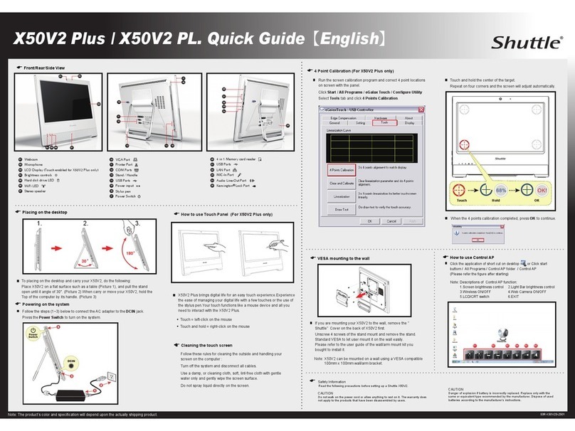
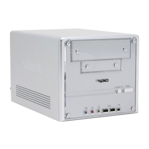
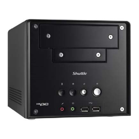
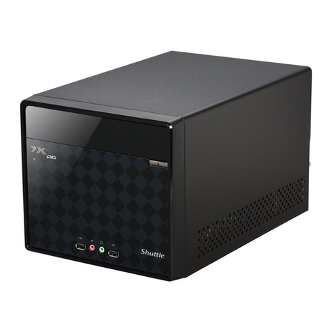
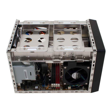
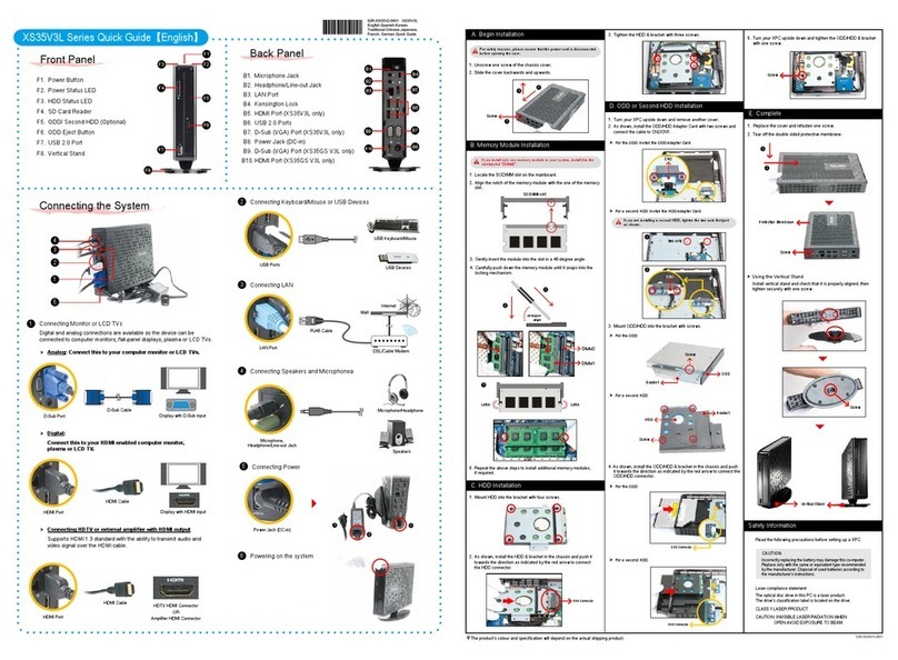
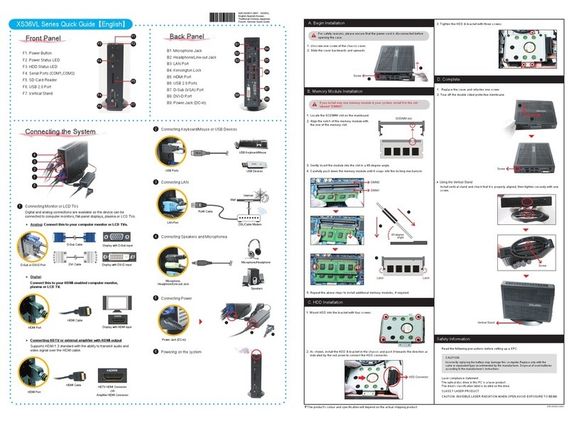
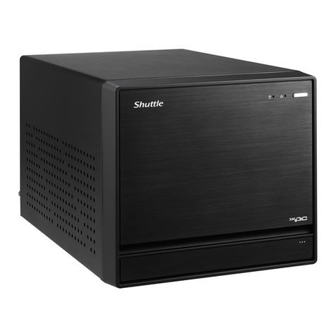
B1.ACPowerSocket
B2.SerialPort(Optional)
B3.DisplayPort
B4.HDMIPort
B5.USB3.0Port
B6.eSATAPort
B7.LANPort
B8.ClearCMOSButton
B9.FrontSpeakerOut(L/R)Port
B10.Line-InPort
B11.SideSpeakerOut(L/R)Port
B12.RealSpeakerOut(L/R)Port
B13.Center/Subwoofer
SpeakerOutPort
B14.WirelessLANPerforation
(Optional)
11. FastentheSmartFantothechassiswiththefourthumbscrews.
A.BeginInstallation
1.Unscrew3thumbscrewsofthechassiscover.
2.Slidethecoverbackwardsandupwards.
3.Unfastentherackmountscrewsandremovetherack.
B.CPUandICEInstallation
Forsafetyreasons,pleaseensurethatthepowercordis
disconnectedbeforeopeningthecase.
1.UnfastentheICEfanthumbscrewsonthebackofthechassis.
2.UnfastenthefourICEmoduleattachmentscrewsandunplugthefan
connector.
3.RemovetheICEmodulefromthechassisandputitaside.
1.UnlocktheDIMMlatch.
2.Alignthememorymodule'scutoutwiththeDIMMslotnotch.
SlidethememorymoduleintotheDIMMslot.
C.MemoryModuleInstallation
3. Checkthatthelatchesareclosed,andthememorymoduleisrmlyinstalled.
E.InstallationofExpansionCards
1.Unfastentheexpansionslotbracketscrews.
Removethebackpanelbracketandputitaside.
F.InstallationofExpansionCards
2.InstallthePCIex4/PCIex16cardintothePCIex4/PCIex16slots.
3.Securethebracket.
G.Complete
Pleasepressthe"Del"keywhilebootingtoenterBIOS.Here,
pleaseloadtheoptimisedBIOSsettings.
Themaximumsizeacceptablefordisplaycardsis
267mmx120mmx34.6mm.
1.Replacethecoverandrefastenthethumbscrews.
2.Complete.
Makesurethatthemotherboardsupportsthememory.
Itisrecommendedthatmemoryofthesamecapacity,brand,
speed,andchipsareused.
(GotoShuttle'swebsiteforthelatestmemorysupportlist.)
Memorymoduleshaveafoolproofdesign.Amemorymodulecan
beinstalledinonlyonedirection.Ifyouareunabletoinsertthe
memory,switchthedirection.
GuidelinesforMemoryConguration
BeforeinstallingDIMMs,readandfollowtheseguidelinesformemory
conguration.
Installingamemorymodule
DDR4andDDR3/DDR2DIMMsarenotcompatibletoeachotherorother
DDRDIMMs.
BesuretoinstallDDR4DIMMsonthismotherboard.Followthesteps
belowtocorrectlyinstallyourmemorymodulesinthememorysockets.
Repeattheabovestepstoinstalladditionalmemorymodules,
ifrequired.
ADDR4memorymodulehasacutout,soitonlytsinonedirection.
4.Firstunlockandraisethesocketlever.
This1151-pinsocketiseasilydamagedandpinsbendquickly.Always
useextremecarewheninstallingaCPUandlimitthenumberoftimes
thatyouremoveorchangetheCPU.BeforeinstallingtheCPU,make
suretoturnothecomputerandunplugthepowercordfromthe
poweroutlettopreventdamagetotheCPU.
FollowthestepsbelowtocorrectlyinstalltheCPUintothe
motherboardCPUsocket.
PleasebeawareoftheCPUorientation,DONOTforcetheCPUinto
thesockettoavoidbendingofpinsanddamageofCPU!
6. PleaseorientatetheCPUcorrectlyandaligntheCPUnotcheswiththe
socketalignmentkeys.MakesuretheCPUsitsperfectlyhorizontal,then
pushitgentlyintothesocket.
DONOTtouchsocketcontacts.ToprotecttheCPUsocket,always
replacetheprotectivesocketcoverwhentheCPUisnotinstalled.
Socket
1151
CPU
TrianglePin1
Marking
ontheCPU
LTheproduct'scolourandspecicationsmayvaryfromtheactuallyshippingproduct.
5.ConnecttheSerialATAandpowercablestotheHDD.
3.ConnecttheSerialATACabletothemotherboard.
4.Placetherackinthechassisandrefastentherack.
1. LoosenthepurselockandseparatetheSerialATAandpowercables.
7. Closethemetalloadplate,lowertheCPUsocketleverandlockinplace.
8.SpreadthermalpasteevenlyontheCPUsurface.
5.Tearotheprotectivemembranefromthemetalloadplate.Liftthe
metalloadplateontheCPUsocket.
Dual-ChannelmodePopulationRule
InDual-Channelmode,thememorymodulescantransmitandreceive
datawithtwodatabuslinessimultaneously.EnablingDual-Channel
modecanenhancethesystemperformance.Thefollowingillustrations
explainthepopulationrulesforDual-Channelmode.
DIMM1(Black),Installed
DIMM2(Blue),Installed
DIMM3(Black),Installed
DIMM4(Blue),Installed
A
B
9. ScrewtheICEmoduletothemainboard.Notetopressdownonthe
oppositediagonalcornerwhiletighteningeachscrew.
10.Connectthefanconnector.
J3
FanConnectors(FN1,FN2)
J2
USBHeader(USB1,USB2)
1=5V_USB 2=5V_USB
3=USB A- 4=USB B-
5=USB A+ 6=USB B+
7=GND 8=GND
9=NULL 10=GND
J1
FrontAudioHeader(JP2)
1=MIC_L 2=GND
3=MIC_R 4=Front_Detect
5=LINE_R 6=Mic_detect
7=sense 8=NULL
9=LINE_L 10=Line_Detect
J4
USB3.0Header(JP5)
1=5VCC 2=A_RX_N
3=A_RX_P 4=Ground
5=A_TX_N 6=A_TX_P
7=Ground 8=A_Data_N
9=A_Data_P 10=OC
11=B_Data_P 12=B_Data_N
13=Ground 14=B_TX_P
15=B_TX_N 16=Ground
17=B_RX_P 18=B_RX_N
19=5VCC 20=NULL
DIMM1(Black),Empty
DIMM2(Blue),Installed
DIMM3(Black),Empty
DIMM4(Blue),Installed
MotherboardIllustration
BackPanel
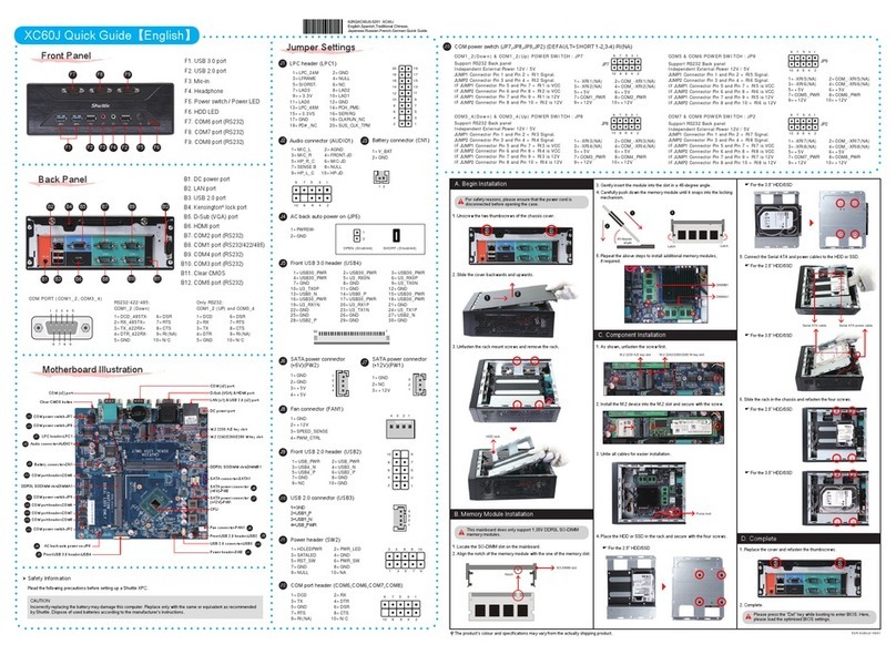
SZ170R8QuickGuide【English】
FrontPanel JumperSettings
Pleasedonotapplyexcessamountofthermalpaste.
2. InstalltheMiniPCIEcard/M.2SSDintotheMiniPCIEslot/M.2slotand
securewithscrew.
D.ComponentInstallation
53R-SZ1703-H501
SafetyInformation
ReadthefollowingprecautionsbeforesettingupaShuttleXPC.
CAUTION
Incorrectlyreplacingthebatterymaydamagethiscomputer.Replaceonlywiththesame
orequivalentasrecommendedbyShuttle.Disposalofusedbatteriesaccordingtothe
manufacturer'sinstructions.
Laser compliance statement
TheopticaldiscdriveinthisPCisalaserproduct.
Thedrive'sclassicationlabelislocatedonthedrive.
CLASS 1 LASER PRODUCT
CAUTION:INVISIBLELASERRADIATIONWHENOPEN.AVOIDEXPOSURETOBEAM.
PCIex16slot
PCIex4slot
SerialATACable
SerialATAPowerCable
J7
PowerConnector(JP4)
1=+HD_LED 2=PWR_LED
3=-HD_LED 4=GND
5=RST_SW 6=PWR_SW
7=GND 8=GND
9=NA 10=NULL
97531
108642
J6
COMHeader(COM1)
1=DCD 2=RXD
3=TXD 4=DTR
5=Ground 6=DSR
7=RTS 8=CTS
9=NA 10=NULL
97531
108642
13579
246810
1
3
5
7
9
2
4
6
8
10
1=Ground
2=+12V
3=SPEED_SENSE
4=PWM_CTRL
FanConnector
1
2
3
4
4
3
2
1
11 12 13 14 15 16 17 18 19 20
10987654321
ThermalPaste
applicationarea
Cutout
Latch Latch
Notch
DDR4288pin1.2V
67*2=134pin
77*2=154pin
2
1
3
FanConnector
J5
LPCHeader(LPC1)
10
9
8
7
6
5
4
3
2
1
20
19
18
17
16
15
14
13
12
11
1=+12V 2=5V
3=5VSB 4=SERIRQ
5=CLK_48M 6=CLK_33M
7=SIO_RST 8=LFRAME
9=LAD3 10=LAD2
11=-12V 12=3VSB
13=NA 14=LDRQ0
15=SIO_PME 16=LAD1
17=LAD0 18=+3.3V
19=GND 20=NULL
Metalloadplate
Tearotheprotective
membrane.
MiniPCIEslot
1.Asshown,unfastenthescrewrst.
M.2slot
J2
J3
J4
J7
J6
4x288pinsDDR4DIMMSlot
SideSpeakerOut/
RealSpeakerOut/Center/
SubwooferSpeakerOutPort
FrontSpeakerOut/Line-InPort
2xUSB3.0&1xLANPort
ATXPowerConnector-PWR1
ATXPowerConnector-ATX1
FrontAudioHeader-JP2
USBHeader-USB1
PowerConnector-JP4
LGA1151
FANConnector-FAN1
2xDisplayPort
OnePCIex4Slot
OnePCIex16Slot
2xUSB3.0&1xeSATAPort
ClearCMOSButton
LPCHeader-LPC1
USB3.0Header-JP5
2xUSB3.0&1xHDMIPort
COMHeader-COM1
Intel
®
Z170Chipset
USBHeader-USB2
MiniPCIeSlot
M.2Slot
J5
J2
J1
J3
FANConnector-FAN2
SATA3.06Gb/sConnector
-SATA1,SATA2,SATA3,SATA4
B1
B2
B9
B12
B13
B11
B14
B5
B8B7
B3 B4
B6
B10
F1. PowerOnButton
F2. PowerLED
F3. HDDLED
F4. USB3.0Port
F5. MicIn
F6. Headphones
F1
F2
F3
F6F5
F4
1
2
SATA3.0Connectors
SerialATAHDD
1st
2nd
3rd
4th
SATA3.0Connectors
2.PlacetheHDDintherackand
securewithscrewsfromtheside.
6.Repeatthesestepstoinstalluptofour3.5"HDDs,ifdesired.
VGACardPCB
Chassis
Cover
5mm 34.6mm
PCIex16/PCIex4slots
Themaximumheight
formemorymodule
is42mm.
42mm
62R-SZ1701-5201 SZ170R8
English.Spanish.Korean.
Traditional Chinese.Japanese.
French. German Quick Guide
