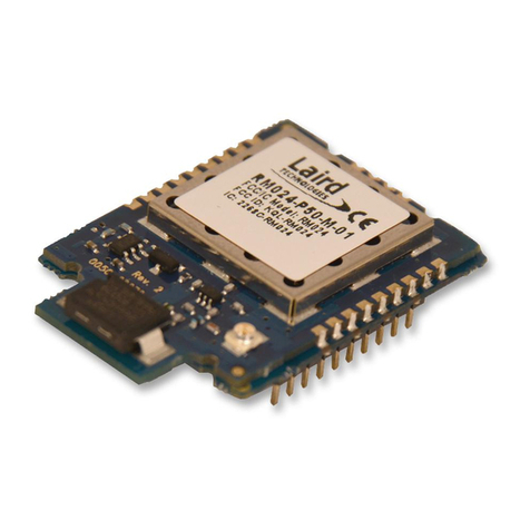
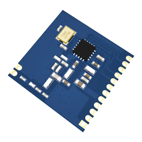
Shuttle WM168b User manual

User’s Guide
for
Shuttle Wireless LAN USB Module

Shuttle®
User’s Guide for Wireless LAN USB Module
Manual Version 1.0
FCC Regulation Information
TheequipmenthasbeentestedandfoundtocomplywiththelimitsforaClassB
DigitalDevice,pursuant to part 15 of the FCC rules. These limits are designed to
providereasonableprotectionagainstharmful interferenceina residentialinstalla-
tion.This equipmentgenerates,uses andcanradiate radiofrequencyenergy and,
if not installed and used in accordance with the instructions, may cause harmful
interferenceto radiocommunication.However, there isnoguarantee thatinterfer-
encewill notoccurin aparticularinstallation. Ifthisequipment doescauseharmful
interferenceto radio or television reception, which can bedetermined by turning
theequipmentoffandon,the user is encouraged to try to correct the interference
byoneor more of the following measures:
nReorientor relocate thereceivingantenna.
nIncreasethe separation between the equipment andreceiver.
nConnectthe equipmentintoan outlet ona circuit differentfromthat towhichthe
receiveris connected.
nConsultthe dealer or an experienced radio/TV technician for help.
Theequipmentis for home or office use.
Copyright
Copyright©2003byShuttle®Inc.AllRightsReserved.Thispublication,includingall
photos,illustrations, and software,isprotected under internationalcopyrightlaws.
Reproducingany ofthe materialcontainedherein isprohibitedwithout theconsent
ofthe publisher. Disclaimer
Shuttle®Inc.shallnotbe liableforany incidental orconsequential damages result-
ingfrom the use of this product. This company makesnorepresentationsor war-
rantiesregardingthe contents of this manual. This company reserves the right to
revisethe manual or make changes in the specificationsofthe product described
hereinat anytimeand without noticeand without obligationtonotify anypersonof
suchrevision or changes.
General Notice: All the other trademarks and registered trademarks are the
property of their respective owners.

1. INTRODUCTION...............................................................1
1.1 Features..........................................................................1
1.2 Package Contents................................................................2
1.3 System Requirements...........................................................2
1.4 The802.11b Wireless LAN USB Module...................................2
2. INSTALLATION OF THE 802.11b WIRELESS LAN USB
MODULE............................................................................3
2.1 Hardware Setup.....................................................................3
2.2 Installation Precaution...........................................................7
2.3 Installing the WLANDriver......................................................8
2.4 InstallationNotes - Windows XP.............................................10
2.5 Verifying a Successful Installation.........................................12
3. CONFIGURATION FOR WINDOWS XP..............................13
3.1 ToConnectanAvailableNetworkviaWirelessZeroConfiguratio....
.....................................................................................13
3.2 ToConfigure theWirelessNetworks Properties.......................14
3.3 AccesstoSpecific WirelessNetwork Types...........................17
4. SHUTTLE WIRELESS LAN BASICS..................................18
4.1 Tray Icon.............................................................................18
4.2 Right-ClickMenu of the Tray Icon...........................................19
Wireless Radio On...............................................................19
Wireless Radio Off...............................................................19
Remove Status Icon.............................................................19
Wireless Network Status......................................................20
AdvancedConfiguration........................................................20
WEP Encryption..................................................................20
Version Information.............................................................20
Table of Contents

4.3 Program Controls................................................................20
The Status Tab...............................................................21
The Configuration Tab..........................................................23
The Encryption Tab..............................................................25
The Site Survey Tab.............................................................27
The About Tab.....................................................................27
APPENDIX A: TROUBLESHOOTING.....................................28
UninstallShuttle Wireless LAN andtheModule’sDriver.................28
The802.11bWLANUSBModule Does NotWorkProperly.............31
UpgradeShuttle Wireless LANandtheModule’s Driver.................31
Reset the Country Selection.......................................................33
APPENDIX B: SPECIFICATIONS............................................34
APPENDIX C: GLOSSARY.......................................................35

1
1. INTRODUCTION
The802.11bWireless LAN USB Module aims to let your XPC quickly
and seamlessly communicate with a 802.11b (at up to 11 Mbps)
networks. Wireless LAN is local area networking without wires,
which uses radio frequencies to transmit and receive data between
PC’s or other network devices. With this wireless LAN USB Mod-
ule, surfing on the Internet couldn’t be any easier. Simply install
the USB Module into the reserve area, launch the attached friendly-
interfaced program – Shuttle Wireless LAN to configure the Mod-
ule, and you will be ready to experience how the LAN (local area
network) can be accessed anywhere. You can operate the network
ineither an independentmode or aninfrastructure mode. Theformer,
which is also known as peer-to-peer or ad-hoc network, lets you
directly make connection with other wireless-equipped computers,
and the later, the so-called infrastructure network, allows you to
communicate with wired LAN via an access point.
To obtain the complete benefits your 802.11b Wireless LAN USB
Module provides, please read this manual carefully before using it.
This module is applicable for: SS51G/ SB51G/ SK41G/ SN41G2/
SB52G2/ SB61G2/ SN45G/ SB75G2.
1.1 Features
With 802.11b Wireless LAN USB Module, you can
-exchange data over the air, which minimizes the need for
wired connections
-possess the portability and mobility of wireless networking
connectivity wherever you are
-operate Ad-Hoc or Infrastructure modes
-utilize up to 128-bit WEP encryption
-enjoy high-speed data transfer rate up to 11 Mbps
-employ automatic data rate switching which offers maximum
reliability, throughput and connectivity
-monitor and configure the network via the supplied friendly-
interfaced application ~Shuttle Wireless LAN Tool
2
1.2 Package Contents
Before starting installation, please make sure the package you
purchased includes the following items:
aOne 802.11b Wireless LAN USB Module
aOne Antenna
aTwo Washers
aOne Daughterboard
aOne USB data cable
a4 x Screws
aOne Setup Wizard CD-ROM with Installation Guide
aOne User Manual
If any of the items listed above are missing or damaged, please
contact your distributor.
1.3 System Requirements
To properly operate your 802.11b Wireless LAN USB Module, your
computer must meet the following minimum requirements:
a300 MHz processor or higher
a32 MB RAM or above
aA CD-ROM drive
aMicrosoft Windows 98 SE/ Me/ 2000 or Windows XP
1.4 The 802.11b Wireless LAN USB Module
Your 802.11b Wireless LAN USB Module should be located in the
USB port on the back panel of your XPC.

3
2. INSTALLATION OF THE 802.11b
WIRELESS LAN USB MODULE
It’s free and easy for you to install your 802.11b Wireless LAN USB
Module and the attached software - Shuttle Wireless LAN Tool.
Simply attach the hardware and with a few clicks of the mouse,
you will complete the installation. To have the 802.11b WLAN USB
Module operated appropriately, please read and follow the instruc-
tions below carefully.
2.1 Hardware Setup
Refer to the following steps to arm your XPC with the
Module.
-STEP1.
Remove the case by unfas-
tening the three screws on
the back panel.
-STEP2.
Use a 6mm screwdriver hori-
zontally puncture the reserve
hole from outside in. Once the
screwdriver can pass through
the reserve hole, make sure
the cover is completely de-
tached from the chassis.
Note :If the cover still does not detach, carefully bend it by pushing
down from the inside of the chassis.

4
1
2
1
0
C
N
1
P
A
L
-
B
9
4
V
-
0
JM644
V
E
R
:
1
.
0
V1
D1-
D1+
GND
GND
V2
D2-
D2+
GND
GND
-STEP3.
Screwthe daughterboardto
the front chassis, on which
there are two locators as
shown in the picture below.
-STEP4.
Establish a link between the daughterboard and the mainboard with
a USB cable by connecting one end of it to the black USB port on
the daughterboard in advance.
-STEP5.
Connect the other end of
the USB cable to a USB
header on the mainboard.
Caution :The white USB sockets should be facing outwards as you install the daughterboard.
Note :Make sure all the connectors are aligned in the correct direction.
Note :For SS51G, SB51G, SK41G, SN45G user, if user has installed the PN21 bluetooth module,
use the existing daughterboard and connect the USB interface to the spare slot.

5
Caution:When inserting the cable
connector, check the socket align-
ment and only push horizontally.
Do not turning or twist the cable.
-STEP6.
Screw the Wireless LAN
USB Module to the two
holes on the upside of the
chassis arm, near the rear
of the XPC.
-STEP7.
Install the antenna cable connector flushly into the back chassis
via the side reserve hole.
Antenna cable connector
Note:If some difficulty is found while inserting the antenna socket into the reserve hole,
make sure the surface is clean. Finally, check the alignment and then use some more force .
Shuttle
P/N :PN11
0678
!
FC
Wireless LAN USB Module
Antenna cable
connector
Screws
USB module cable
MAC:
Y26110210021

6
Use a washer and lock to secure the antenna from the outside.
-STEP8.
Connect the USB module
cable to the daughterboard
by attaching one end of the
USB cable to either of the
two white USB ports on the
daughterboard.
-STEP9.
Connecting the antenna with header and secure it properly. Adjust
the antenna to the vertical position for good reception. Double check
if all the connectors are secure properly.
-STEP10. Fasten the case and completed the installation.
12
Note :Make sure all the connectors are aligned in the correct direction.

7
2.2 Installation Precaution
Before the installation, please ensure the 802.11b WLAN USB
Module has been setup in your XPC. To detect the existence of the
Module, please follow the procedures below.
1. Click Start on the taskbar and choose Control Panel from the
Settings menu.
2. Select System to open the System Properties dialog box, and
then under the Hardware tab, click the Device Manager buton
to open the Device Manager dialog box.
3. Double-click Other devices from the list to display the item -
IEEE 802.11b PRISM3 USB, and this presents the exist ence
of your 802.11b WLAN USB Module.
Now you may proceed with the next topic to start installing the
drivers for the module.
The Device Manager Dialog Box
Note :If you don’t find the module, please turn off the XPC and replug
the module, or contact your dealer immediately.

8
2.3 Installing the WLAN Driver
a) Insert the supplied CD into your CD-ROM drive, and open Utility
\Wireless LAN folder to run AutoRun.exe.
b) From the prompted startup window, chooseInstall WLAN Driver
to begin the installation.
c) Click Next in the Shuttle Wireless LAN window to proceed.
The system will start to copy the drivers found.
The Startup Window
The Shuttle Wireless LAN Window

9
d) On the Maintenance Complete screen, choose Yes, I want
to restart my computer now, and then click Finish to restart
the computer.
e) After rebooting, you shall find the Shuttle Wireless LAN
icon appearing in the system tray. The installation is entirely
finished at the moment. Double-click the icon to launch the ap-
plication and open the PRISM Wireless Settings dialog box, in
which you may freely arrange your network connection after-
wards.
For more details about Shuttle Wireless LAN, please refer to
Shuttle Wireless LAN Basics in this manual.
The Maintenance Complete Screen
Note :Instead, if the system displays the Update WLAN Driver Failed
message box, click OK, and then refer to the last topic - Installa-
tion Precaution for more details.

10
2.4 Installation Notes - Windows XP
If your current system is running Windows XP, you shall find that
two tabs are contained in the PRISM Wireless Settings dialog
box after you’ve followed the instructions above and successfully
installed the drivers. However, normally, the dialog box should con-
sist of five tabs. This is because Windows XP has its built-in con-
figuration tools – Windows XP Zero Configuration to assist you
in networking activities. It is recommended to utilize the attached
Shuttle Wireless LAN to enjoy the maximum benefits it can bring.
Thus, to employ your Shuttle Wireless LAN under Windows XP,
please proceed to the next step to change the default settings of
Windows Zero Configuration to Shuttle Wireless LAN.
The Shuttle Wireless LAN Tray Icon
The PRISM Wireless Settings Dialog Box

11
a) Right-click the Network
Connections icon on the
task bar to open the Wir-
eless Network Connec-
tion Status dialog box,
then select Properties.
b) Choose the Wireless
Networks tab in the
Wireless Network
Connection Properties
dialog box, and remove
the tick from the Use
Windows to configure
my wireless network
settings checkbox.
c) Click OK. Now, you have
successfully removed the
Windows Zero Configu-
ration.
To monitor and configure the network via Shuttle Wireless LAN,
double-click its tray icon, and you shall find four tabs contained in
the popped up PRISM Wireless Settings dialog box this time. For
more information on Shuttle Wireless LAN, please refer to Shuttle
Wireless LAN Basics below.
The Wireless Network
Connection Status Dialog Box
The Wireless Network ConnectionProperties Dialog Box

12
2.5 Verifying a Successful Installation
To confirm that your 802.11b Wireless LAN USB Module is prop-
erly installed, please follow the procedures below.
1. Right-click the My Computer desktop icon and choose
Properties from the opened menu.
2. In the System Properties dialog box, choose Device Man-
ager if you are under Windows 98 or Me. If you are operating
Windows 2000 or XP, click the Hardware tab, and then choose
the Device Manager button.
3. In the opened window, expand Network adapters to find the
USB Module - WirelessLAN PRISM3 IEEE802.11b WM168 USB
Module. Right-click on the item and choose Properties.
4. From the opened dialog box, on the General tab, find the de-
scriptions under the Device Status panel to learn if the module
is working properly. However, if there’s an error message shown,
right-click the USB Adapter item and choose Uninstall from the
opened menu, to which a red or yellow icon is attached beside,
in the Device Manager dialog box. Then restart your system
and go through the installation procedures again.
Thefollowing pictureindicates a successfulinstallation ofthe 802.11b
Wireless LAN USB Module.
The Device Manager Dialog Box

13
3. CONFIGURATION FOR WINDOWS XP
As you already know, Windows XP has its built-in configuration
tools – Windows XP Zero Configuration, to assist you in some
basic configurations of wireless network connection. The service
starts right after the completion of the installation of 802.11b WLAN
USB Module, and you will find the icon automatically appears in
your system tray like the following picture shows.
Please refer to the desired topics below to look for more details
about utilizing your 802.11b WLAN USB Module via Wireless Zero
Configuration.
3.1 To Connect an Available Network via
Wireless Zero Configuration
1. Double-click the Wireless Network Connection icon.
2. In the opened Connect to Wireless Network dialog box, the
currently available networks are listed in the Available net-
works field. From the list, choose an item that you intend to
connect with.
3. If the chosen entry requires
a WEP encryption key and
also automatically provides
it, leave the Network Key
fieldblank and then choose
the Connect buttonto build
the connection. Otherwise,
you will need to manually
enter the identical key in
the Network Key field be-
fore clicking Connect.
4. If the connection is established, there will be a pop-up message
shown beside the Wireless Network Connection icon on the
system tray. You could obtain the information on the status of
connection from the message.
The Wireless Network Connection Icon
The Connect to Wireless Network Dialog Box

14
3.2 To Configure the Wireless Networks Properties
If you cannot establish a con-
nection with the chosen entry
or you wish to configure fur-
ther wireless network connec-
tion settings, choose the
Advanced button in the Con-
nect to Wireless Network
dialogue box.
After clicking Advanced,
you will enterinto the Wire-
less Networks tab of the
Wireless Network Con-
nection Properties dialog
box, in which three other
tabs are found, including
General, Authentication,
and Advanced. The Wire-
less Networks tab in-
cludes almost the main
settings for the networking
connection. Thus, please
check the descriptions be-
low to learn more about the
tab.
The Connect to Wireless Network Dialog Box
Note :For more detailed information about each tab, please refer to
Windows XP Online-Help.
The Wireless Network Connection
Properties Dialog Box

15
The Wireless Networks tab chiefly consists of two sections: Avail-
able networks and Preferred networks.
-Under the Available networks area, all the available access
points or Wireless LAN PC Card equipped computers are displayed.
You may wish to click Refresh to update the list. If you choose
any listed item in the field and then click Configure, the Wireless
Network Properties dialog box will appear as Figure 3-5 shows.
Check the description below the figure to obtain more information
about the dialog box.
-In the Preferred networks area, you could add any displayed
networks to the list by clicking over the intended item from Avail-
able networks and then selecting the Add button. After clicking
Add, the Wireless Network Properties dialog box will appear as
Figure 3-5 displays. Note that to delete any item under the Pre-
ferred networks area, simply click on it and then select the Re-
move button. Additionally, you may adjust the items in the list by
clicking the desired item and then choosing the Move up or Move
down button. It is, however, important to realize that Windows XP
will always choose the first one in the list to establish the network-
ing connection.
Note:Once you choose an item from the Preferred networks list and then click
Properties, the Wireless Network Properties will also be affected.
The Wireless Network Properties Dialog Box

16
-In the opened Wireless Network Properties dialog box, edit
texts in the Network Name (SSID) field to identify the chosen
network entry in the wireless LAN.
-If there’s a need, go to the Wireless network key (WEP) area
below to set the keys as the associated access point or Wireless
LAN PC Card equipped computer requests. To set WEP, select
Data encryption (WEP enabled) and Network Authentication.
Then enter the encryption keys for the network you intend to con-
nect in the Network Key field. Meanwhile, the Key format and
Key length options change the settings according to Network
Key string you just typed. Click OK when you are finished, and
you will return to the Wireless Network Connection Properties
dialog box.
Note:For more details on this tab, you may click the link: setting up wireless
network configuration at the bottom of the Wireless networks tab to
launch the Windows XP Online-Help.
Setting up wireless network configuration
Enter WEP
Table of contents
Other Shuttle Wireless Module manuals