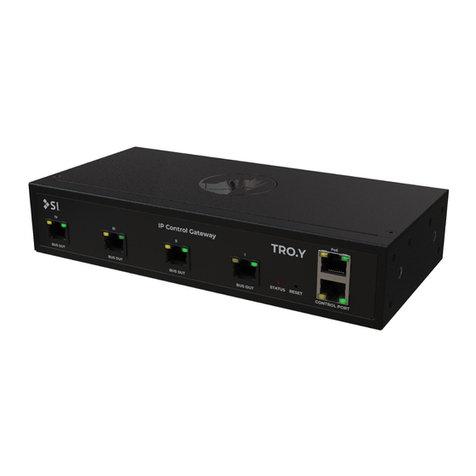
SI TRO.Y User manual

TRO.Y
Installation Instructions
DOC.#400142


Thank you for purchasing an SI product. If you have any questions or need any assistance with your TRO.Y, we would love to
help you.
Technical Support: 512.832.6939
Hours of Support: 7:30am - 5pm CST
screeninnovations.com
Once you nish the install, please go to https://support.screeninnovations.com/accessories/troy/, or
scan the QR code for the programming manual or other resources.


CONTENTS
Introduction . . . . . . . . . . . . . . . . . . . . . . . . . . . . . . . . . . . . . . . . . . . . . . . . . . . . . . . . . . . . . . . . . . . . . . . . . . . . . . . . . . . . . . . . .6
Initial Considerations . . . . . . . . . . . . . . . . . . . . . . . . . . . . . . . . . . . . . . . . . . . . . . . . . . . . . . . . . . . . . . . . . . . . . . . . . . . . . . . .7
Parts in the Box . . . . . . . . . . . . . . . . . . . . . . . . . . . . . . . . . . . . . . . . . . . . . . . . . . . . . . . . . . . . . . . . . . . . . . . . . . . . . . . . . . . 8 - 9
Installation . . . . . . . . . . . . . . . . . . . . . . . . . . . . . . . . . . . . . . . . . . . . . . . . . . . . . . . . . . . . . . . . . . . . . . . . . . . . . . . . . . . . .10 - 15
Connections . . . . . . . . . . . . . . . . . . . . . . . . . . . . . . . . . . . . . . . . . . . . . . . . . . . . . . . . . . . . . . . . . . . . . . . . . . . . . . . .10 - 13
LED Operations . . . . . . . . . . . . . . . . . . . . . . . . . . . . . . . . . . . . . . . . . . . . . . . . . . . . . . . . . . . . . . . . . . . . . . . . . . . . . . . . .14
Button Operations . . . . . . . . . . . . . . . . . . . . . . . . . . . . . . . . . . . . . . . . . . . . . . . . . . . . . . . . . . . . . . . . . . . . . . . . . . . . . . .15
256 shade systems . . . . . . . . . . . . . . . . . . . . . . . . . . . . . . . . . . . . . . . . . . . . . . . . . . . . . . . . . . . . . . . . . . . . . . . . . . . . . . . . .16
Tro.y topology example . . . . . . . . . . . . . . . . . . . . . . . . . . . . . . . . . . . . . . . . . . . . . . . . . . . . . . . . . . . . . . . . . . . . . . . . . . . . . .17
Rack Mounting . . . . . . . . . . . . . . . . . . . . . . . . . . . . . . . . . . . . . . . . . . . . . . . . . . . . . . . . . . . . . . . . . . . . . . . . . . . . . . . . .18 - 24
Din Rail Mounting . . . . . . . . . . . . . . . . . . . . . . . . . . . . . . . . . . . . . . . . . . . . . . . . . . . . . . . . . . . . . . . . . . . . . . . . . . . . . .25 - 27
Structured Wire Box Mounting . . . . . . . . . . . . . . . . . . . . . . . . . . . . . . . . . . . . . . . . . . . . . . . . . . . . . . . . . . . . . . . . . . . .28 - 29
Troubleshooting Ethernet . . . . . . . . . . . . . . . . . . . . . . . . . . . . . . . . . . . . . . . . . . . . . . . . . . . . . . . . . . . . . . . . . . . . . . . . . . . .30
Troubleshooting Controls . . . . . . . . . . . . . . . . . . . . . . . . . . . . . . . . . . . . . . . . . . . . . . . . . . . . . . . . . . . . . . . . . . . . . . . . . . .31
Additional Accessories . . . . . . . . . . . . . . . . . . . . . . . . . . . . . . . . . . . . . . . . . . . . . . . . . . . . . . . . . . . . . . . . . . . . . . . . . .32 - 33
Installation complete - starting web server . . . . . . . . . . . . . . . . . . . . . . . . . . . . . . . . . . . . . . . . . . . . . . . . . . . . . . . . . . . . .34

6
INTRODUCTION - TRO.Y
• Embedded commissioning software
• 485 programming
• Powered via PoE
• 4 segmented 485 bus line
• Single integration point for third-party automation systems over IP or RS232
• Compatible with SDN 2.0 (485)
• Works with Somfy Synergy™ API
• Advanced Lutron compatibility
• Din Rail mounting capability
Features
TRO.Y is an IP Control gateway that allows 3rd party integration with 485 shades via PoE and RS232. Also
TRO.Y allows advanced control options for all shade types including RTS and Zigbee via its TLS encrypted link.
Compatible wireless controllers include LinkProZ and TaHoma. Another feature allows TRO.Y to use handheld
remotes and keypads to control any shade types using super groups.

7
INITIAL CONSIDERATIONS
Thank you for your purchase of TRO.Y.
This is designed to be installed indoors, Rack or Din mounted. Should be mounted in close proximity to the
Janus units not exceeding 200' for each port(refer to pg. 9 for more info.).
TRO.Y has 4 485 ports, in order to segment and improve 485 bus. When deploying the shades where ever
possible its a best practise to divide the shades into 4 segments. This will improve performance and lower
latency on commands.
For example:
With 32 shades, and 4 Janus units, the preferred method of wiring is 1 Janus per port or 8 shades per port.

8
PARTS IN THE BOX
Troy
Universal Rack Ears (2)
Rack Mount Fascia
Universal DIN Rail Bracket (2)
(1) 48v Passive PoE
Injector - Brick
(1) Injector Power
Cable
(1) CAT5e

9
DIN Rail Screws (2)
Universal Mounting
Screws (10)
Universal DIN Rail Rack Mount Screws (4)
Long Rack Ear 1.5 mm Hex Tool

10
485 Ports (1 - 4)
High speed
control port
Programming
button
PoE port
Status LED
INSTALLATION - CONNECTIONS
Connecting Power
TRO.Y uses PoE for Power: Connect to PoE switch or included power injector.
(PoE 802.3 - compatible with all versions of PoE AT/BT)
Connections
Cat 5e

11
INSTALLATION - CONNECTIONS
Connecting TRO.Y
TRO.Y offers the ability to connect up to 4 segments utilizing the 485 ports, using CAT5e/6 cable. For the
highest level of performance, each segment should not contain more than 64 shades (for a total of 256 shades).
If you have a system that contains more than 256 shades, we recommend adding an additional TRO.Y.
Pin 1
Pin 8
SDN (485) connection
Data +(WHT/ ORG)
Data - (ORG)
N/A (WHT/ GRN)
N/A (GRN)
Power + (BLUE)
Ground - (WHT/ BRWN)
Ground - (BRWN)
Power + (WHT/ BLUE)
485 ports 1 through 4
Upto 200' max. CAT 5e or better
SDN (485) connection
Data +(WHT/ ORG)
Data - (ORG)
N/A (WHT/ GRN)
A (GRN)
Power + (BLUE)
Ground - (WHT/ BRWN)
Ground - (BRWN)
Power + (WHT/ BLUE)
High speed control port
232 connection EIA-561 (DCE)
Ground (SG)
N/A
N/A
Data Output (RxD)
N/A
N/A
N/A
Data Input (TxD)
Upto 120' max. CAT 5e or better
SDN (485) connection
Data +(WHT/ ORG)
Data - (ORG)
N/A (WHT/ GRN)
N/A (GRN)
Power + (BLUE)
Ground - (WHT/ BRWN)
Ground - (BRWN)
Power + (WHT/ BLUE)
PoE
802.3 connection
DC + A (WHT/ORG)
DC + A (ORG)
DC - B (WHT/GRN)
N/A (BLUE)
N/A (WHT/BLUE)
DC - B (GRN)
DC - D (WHT/BRWN)
DC - D (BRWN)
Upto 328' max. CAT 5e or better
High speed control port settings:
BAUD rate - 4800 - 56k
Control bits - 8
Parity - None
Stop bits - 1

12
INSTALLATION - CONNECTIONS
Connecting BUS Devices without Janus
All 4 ports can be used to connect 485 devices, however no Bus power is provided by TRO.Y.
Data Pass-
through Input
Power/Data
Output
Bus Power
Supply
Data Hub
Device Device DeviceDevice Device
Stub length must not exceed 200’
TRO.Y
To IP Network
PoE CAT - 5e
or higher cable
485

13
INSTALLATION - CONNECTIONS
Connecting IP Control
PoE Connection provides 3rd party IP control, wireless control and connection to other TRO.Y s.
UTP Face
IP Control
Note: Connect TRO.Y ports 1- 4 to BUS IN on Janus.

14
Status LED OFF
No power/Reboot
Status LED ON
Power(Red)
Port Left LED OFF
(Yellow)
Left LED ON (Yel-
low)
Left LED
blinking
Right LED
OFF (Green)
Right LED ON
(Green)
Right LED Flashing
(Green)
Bus Out I Bus Idle (bus
connected)
End of Bus Line
(not connected)
N/A N/A N/A With Bus data activity
Bus Out II Bus Idle (bus
connected)
End of Bus Line
(not connected)
N/A N/A N/A With Bus data activity
Bus Out III Bus Idle(bus
connected)
End of Bus Line
(not connected)
N/A N/A N/A With Bus data activity
Bus Out IV Bus Idle (bus
connected)
End of Bus Line
(not connected)
N/A N/A N/A With Bus data activity
Control
Port
N/A N/A N/A N/A When enabled With Data activity
PoE port No Ethernet link Ethernet Link Ethernet
Data Activity
10 Mbps 100 Mbps N/A
INSTALLATION - LED OPERATION
LED information table

15
BUTTON FUNCTIONALITY:
Note: Use a thin tool like a paper clip.
Button Press - Disables security for 5 min.
(Use for password recovery)
Note: All LEDs will turn off once you reach the software reset.
Button Hold (3 sec) - Hardware Reset
Button Hold (10 sec) - Software Reset
INSTALLATION - BUTTON OPERATION

16
256 SHADE SYSTEMS
End of
Line
485
End of
Line
485End of
Line
485
End of
Line 485

17
TRO.Y TOPOLOGY EXAMPLE
LAN IP Connection
to TRO.Y
3rd party Control
System
PoE/LAN Global
Connection to
3rd party
controls,
LinkProZ and
other TRO.YS
IP Connection
to LinkProZ
To other
TRO.YS
over IP
To Zigbee and
RTS shades
To 485 shades
Button presses from 3rd
party app on Ipad sent
to TRO.Y
Built-in web server
Welcome
Wireless Controller

18
Screw Hole Locations
TRO.Y can be mounted in various ways using these 10 screw hole locations.
RACK MOUNTING
Janus and TRO.Y share all the same mounting features and accessories. There are
innite ways to install them together or seperately.
Some of the Din Rail
screw locations

19
RACK MOUNTING
Using Universal Rack Ear
The symmetrical hole pattern of the TRO.Y Universal Rack Ear allows these multi-functional Brackets to be
mounted on either side of TRO.Y in any orientation. This makes it possible to mount TRO.Y to virtually any
surface in multiple positions.

20
1. Half Rack
TRO.Y can be mounted in a standard half rack using 2 Universal Rack Ears.
9.73” (247mm)
RACK MOUNTING
Note: Half Rack hole spacing must
be 9.73”(247mm)
Other manuals for TRO.Y
1
Table of contents
Other SI Gateway manuals
Popular Gateway manuals by other brands

RTA
RTA 460PSTCP-N700 Product user guide

Thermokon
Thermokon EasySens SRC-KNX Operating and installation instructions

Atop
Atop MB5404D-X Series Hardware installation guide

Everynet
Everynet CloudCell 4G installation manual

fafnir
fafnir GL-X300B Installation and configuration

Moxa Technologies
Moxa Technologies MGate 5105-MB-EIP Quick installation guide