SIASUN GCR Series User manual

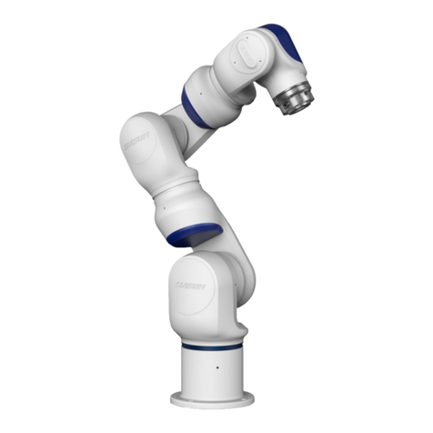
GCR Series Collaborative Robot
User Manual
(Software)
Robot Model GCR20-1100 & GCR14-1400
Robot Version 1.2.15
User interface Version 2.2.14
SIASUN Co., Ltd

Copyright © SIASUN Co., Ltd. 2019. All rights reserved.
This document and parts must not be reproduced or copied by any third party without the written
permission of SIASUN Co., Ltd.
Trademark Statement
The words or images like “SIASUN” 、“新 松 ”、“SIASUN 新 松 ” and etc are protected by
trademark registration. The registered trademark information can be found in the open trademark
registration information.
All other trademarks or registered trademarks mentioned in this manual are the property of their
respective owners.
Attention
Your purchase of products, services or features, etc., shall be subject to the commercial contract
and terms and conditions of SIASUN Co., Ltd. All or part of the products, services or features
described in this manual may not be within the scope of your purchase or use. Unless otherwise
agreed in the contract, SIASUN Co., Ltd. makes no representations or warranties, either express or
implied, with respect to the contents of this manual.
Due to product version upgrade or other reasons, the contents of this manual will be updated from
time to time. Unless otherwise agreed, this manual is used only as a guide, and all statements,
information and recommendations in this manual do not constitute any guarantee either express or
implied.
SIASUN Co., Ltd.
Address:NO.257 Jinzang Rd. Pudong New District, ShangHai Zip:201206
Website:http://www.siasun-in.com

Contents
1 Preface....................................................................................................................................................1
1.1 Intended Audience............................................................................................................................1
1.2 Representation of warnings and notes.............................................................................................2
1.3 Special statement............................................................................................................................. 3
2 Safety...................................................................................................................................................... 4
2.1 Abstract............................................................................................................................................4
2.2 Limitation of Liability...................................................................................................................... 4
2.3 Risk Assessment............................................................................................................................... 5
2.4 Safety Operations.............................................................................................................................6
2.4.1 Emergency Stop........................................................................................................................6
2.4.2 Movement without Drive Power.............................................................................................. 7
3 Introduction........................................................................................................................................... 8
4 Power On & Power off..........................................................................................................................9
5 User Interface Introduction............................................................................................................... 12
5.1 Jog Page........................................................................................................................................ 12
5.2 Program Page................................................................................................................................18
5.3 Run Page........................................................................................................................................21
5.4 Status Page.................................................................................................................................... 23
5.5 Setting Page................................................................................................................................... 25
5.6 About Page.....................................................................................................................................36
5.7 Disconnect Page............................................................................................................................ 36
6 Robot Programming........................................................................................................................... 37
6.1 Create program..............................................................................................................................37
6.2 Move tab........................................................................................................................................ 41
6.3 Function tab...................................................................................................................................42
6.4 Socket tab: internet communication functions...............................................................................46
6.5 Variable Tab Establishment........................................................................................................... 46
6.6 Example......................................................................................................................................... 47
7 Robot External Communication Protocol........................................................................................ 50

8 Script Language Guide.......................................................................................................................59
8.1 Introduction....................................................................................................................................59
8.2 Data Types and Variables.............................................................................................................. 59
8.2.1 1.6.2.1 Built-in Data Types.....................................................................................................59
8.2.2 1.6.2.2 System Constants........................................................................................................59
8.2.3 Variables................................................................................................................................. 60
8.3 Expression......................................................................................................................................61
8.3.1 Arithmetic Operation Expression........................................................................................... 61
8.3.2 Relational Operation Expression............................................................................................ 61
8.3.3 Logical Operation Expression................................................................................................ 61
8.3.4 Assignment Expression...........................................................................................................62
8.3.5 Function Call Expression........................................................................................................62
8.4 Statement........................................................................................................................................62
8.4.1 While Loop Statement............................................................................................................ 62
8.4.2 Break Statement......................................................................................................................62
8.4.3 Function Definition.................................................................................................................62
8.4.4 Return Statement.................................................................................................................... 63
8.4.5 Conditional Control Statement............................................................................................... 63
8.5 System Function Description.........................................................................................................64
8.5.1 Movement Control..................................................................................................................64
8.5.2 TCP/IP Socket client...............................................................................................................68
8.5.3 System Functions and Peripherals..........................................................................................72
8.5.4 Debug Function...................................................................................................................... 79
8.5.5 Modbus................................................................................................................................... 80

1
1 Preface
1.1 Intended Audience
This document provides operating instructions for the SIASUN GCR
Series Collaborative Robot, so that users can learn more about the robot
basic information and use the robot more safely and conveniently. Be
sure to operate this robot on the basis of careful reading and full
understanding of this document.
This document applies for the following users:
On site robotic engineer
Robotic software engineer
Hardware installation engineer
On site Maintenance engineer
System maintenance engineer
Operators must receive basic training before robot’s operation.

2
1.2 Representation of warnings and notes
The table below defines general hazards related symbols, please read through the
description carefully.
Symbol
Description
Used to warn of emergency situations that, if not avoided, could
result in death or serious personal injury.
Used to warn of potentially dangerous situations that, if not
avoided, could result in death or serious personal injury.
Used to warn of potentially dangerous situations that, if not
avoided, may result in moderate or minor personal injury.
Used to convey device or environmental security warnings that, if
not avoided, may result in damage to the device, loss of data,
degradation of device performance, or other unpredictable results.
Caution does NOT involve personal injury.
Used to highlight important / critical information, best practices
and tips.
"Tips" is not a safety warning message, does not involve
personal, equipment and environmental damage information.

3
1.3 Special statement
This manual is only used as a guide. Its content (such as equipment
appearance, software interface) is based on laboratory equipment
information. The content provided in this manual is of general guidance
and does not guarantee that all usage scenarios cover all models. Due to
the software upgrade and equipment model inconsistency, the content
provided in the manual may NOT be consistent with the robot used by
the user. Please take the information of user equipment as the standard,
this manual will no longer address the differences caused by the above
situations.
The maximum value provided in this manual is the maximum that a
device achieves in a lab-specific scenario that meets the appropriate
standards (For example, constant temperature, humidity, interference free
environment, typical operating conditions and etc.). In reality working
situation, the maximum value of equipment testing may NOT be
consistent with the data provided in the manual, due to different working
conditions, specific working conditions and inconsistent testing methods.

4
2 Safety
2.1 Abstract
This section describes important safety and risk assessments that you
need to be aware when installing, applying, and maintaining on robot and
its components. The user must read and fully understand this information
before the robot is powered on for the first time.
Before performing any operations, be sure to read all operating
instructions provided with the equipment, in particular, instructions that
may endanger personal safety and equipment safety, such as hazards,
warnings, and cautions, to minimize the chance of an accident. When this
document differs from the documentation shipped with the device, the
documentation shipped with the device shall prevail.
The technicians responsible for installing and maintaining the equipment
must be a trained person who has proper methods of operation and all
safety precautions. Only trained and qualified technicians are able to
perform equipment installation and maintenance.
2.2 Limitation of Liability
This information neither includes how to design, install and operate a
complete robot system, nor any peripherals that affect the overall system.
In order to protect personal safety, an outstanding system must be
designed and installed in accordance with the safety requirements
stipulated in the standards and regulations of the country where the robot
is installed.
The robot integrator is responsible for ensuring that the robot system
complies with the applicable safety laws and regulations of the country or
region where the robot is located and that the necessary safety equipment
for the protection of the robot system operator is properly designed and
correctly installed. Limitation of Liability
Specifically including but not limited to the following:

5
Ensure that the robot system meets all basic requirements;
Perform a risk assessment of the complete system;
Ensure the design and installation of the entire system is
accurate;
Make appropriate security settings in the software and
ensure that it will not be modified by the user;
Develop detailed operating instructions;
Issue a declaration of conformity;
Collect all information in technical documents;
Label the integrator's logo and contact information on the
installed robotic system.
SIASUN Co., Ltd. is committed to providing reliable safety information,
but does not assume responsibilities. It is important to declare that even if
all operations are carried out in a safe manner, there is no guarantee that
the robot system will not cause personal and property damage to the user.
2.3 Risk Assessment
Risk assessment is one of the most important tasks that integrators must
accomplish. The robot itself is a partially completed machine, and the
safety of the robot installation depends on how the robot is integrated (e.g.
tools, obstacles and other machineries).
It is recommended that integrators perform risk assessment in accordance
with ISO12100 and ISO10218-2. Alternatively, technical specification
ISO / TS 15066 may be selected as additional guidance. Integrators
performing a risk assessment should consider all procedures during the
entire lifespan of the robot, including but not limited to:
Teach robots when developing robots;
Fault diagnosis and maintenance;
General operation of robot installation.
Risk assessment must be performed before the robot arm is powered on
for the first time. Part of the risk assessment performed by the integrator
is the necessity to identify the correct security configuration settings and
additional protections for emergency stop buttons and / or for specific
robot applications.

6
The following list identifies the significant risks that integrators must
consider. Please note that there may be other significant hazards from
certain robotic devices.
Finger is clamped between joint 4 and joint 5;
Sharp edges and sharp spots on the tool or the tool
connector may cause damage to human skin;
The obstacles sharp edges and sharp spots, which is closed
by the robot trajectory, may be dangerous to human skin;
Sprains or fractures due to impact between the robot
payload and a solid surface;
Consequences due to loosening of bolts used to secure
robotic arms or tools;
Items fall off the tool. For example, due to insufficient
clamping or accidentally power down;
Operating error due to different emergency stop button
allocation and types.
2.4 Safety Operations
2.4.1 Emergency Stop
Emergency stop takes precedence over all the other robot control
operations. Pressing emergency stop will cause all controlled hazards to
stop, removing the motor power from the robot drive. It will remain in
effect until reset manually.
Activate emergency stop button to immediately stop the robot from any
motion. The user must perform a restoration procedure, resetting the
emergency stop button and pressing the "Power On" button on
demonstrator, to resume normal operation. Emergency stop shall not be
used as a risk reduction measure, but as a secondary protective device.
Emergency stop must not be used for normal program stop; constantly
pressing may result in additional unnecessary wear on the robot.

7
2.4.2 Movement without Drive Power
In rare cases, it may be necessary to move one or multiple robot joints in
the event of a robot power failure or an emergency situation that does not
require power, which can force the robot joints to move with the
following method:
Manual brake release: Remove the M3 screws that secure the joint cover
and remove the joint cover. Press the plunger in the small electromagnet
to release the brake.
Manually moving the robot arm is limited to
emergency situation and may damage joints.
If manual release the break, gravity may cause
the robot arm to fall. Always hold the robot arm,
tools and work-pieces when releasing the break.
Image 2.4.2 Manual break release schemata

8
3 Introduction
The following chapter will introduce how to operate the GCR20-1100 &
GCR14-1400 collaborative robot. The user interface version is 2.2.14
and robot version is 1.2.15.

9
4 Power On & Power off
The power button is on the side of the control box. Plug in the 220VAC power cable and
press down the power on button to enable the operation system.
After pressing the power button, the indicator light will turns on. The system initialize
till the welcome page appears on the demonstrator.
Click the “Start” button in the middle of demonstrator to start operating robot.

10
System will show the robot installation orientation and flange loading information. For
example, “Robot install: Longitudinal TCP load 0 kg”. If any information does NOT
match with actual, for safety concern, please modify them from system setting before
any other operations. These parameter settings will affect the zero-gravity manual
jogging function and the collision detection function. Click “Modify” button for further
editing.
Click “OK” button, while the above information has been verified. The white flange
light demonstrates the robot has been power on. The first time power on process may
take a while for initializing. After each axis has been initialized, the stand-by indicators
turn from red to blue on demonstrator. Click “Enable All” button to enable the control of
the robot and release all axial breaks. After the flange light turns blue, which indicates
all axial breaks have been released, the robot is ready to be operated via demonstrator.

11
To disconnect the robot, click the “Disconnect” button from demonstrator home page
top right corner. To shut off the system, click the switch off icon to completely shut off
the system.

12
5 User Interface Introduction
There are 7 tabs on the top of home page. It is called navigation bar. Each tab has an
unique function, such as “Jog(manual move)”,” Program”,” Run”, “Status”, “Setting”,
“About” and “Disconnect”. The default home page is “Jog” after power on the system.
5.1 Jog Page
Click the “Jog” button on the navigation bar will open “Jog” page.
There are 6 navigation buttons on the “Jog” page to help you switch through different
functions: Coordinate button, 3D View button, Joint Move button, Line Move button,
Teach (zero-gravity move) button and Speed button.
1. Current joints position & flange origin position
Selecting the 3D View button, the page will show the current joint positions and the
flange origin position.
Click the joints/ flange origin data will open then “Enter joint Values” window. In
this window you can enter the target position value and move the robot to the target
position. After entering the joint value, hold Press Move button to move the robot,
releasing the button will stop the current movement. Click Cancel to close the
“Enter joint Values” page.

13
2. Coordinate
Click Coordinate button will show the coordinate selection page. The robot will
use base coordinate by default. Base coordinate is established at the bottom of the
robot which is also indicated on the 3D robot view. If you have other attachment
tool installed on the flange, you can also click Tool Coordinate or User
Coordinate. Tool coordinate set tool end as origin. User coordinate origin needs to
be set up by user.
While swapping different coordinates, the robot parameters displayed, jogging
orientation and programming coordinate will be changed respectively.
It is not functional for setting up coordinate when
running program. When programming, it requires to
reset coordinate with functions.
Click Tool Coordinate or User Coordinate to set up coordinate while need, refer
to coordinate setting page.

14
3. 3D View
Click 3D View button to show the robot 3D simulation. The simulation is based on
real robot. The simulation interface will show whether the robot is located at home
position.

15
4. Joint Move
Joint Move is set by default move joint. The blue progress bar shows the current
joint position and the limitation for each joint. Hold left/right button to move
forward and backward. Release the arrow button will stop at current move. The
buttons 1-6 on the demonstrator correspond to the joints 1-6 here.
5. Line Move
Click Line Move button will change to move flange origin window. Holding the
corresponding arrow button will let the robot flange origin to move along the axis.
Releasing the button will stop current move. The X, Y, Z illustrates moves
orientation is along X, Y, Z axis and RX, RY, RZ illustrates flange end rotational
orientation.
Before manually jogging the flange end, Please verify
the coordinate is correct comparing with the real
condition.
6. Traction Teach
While the robot is stopped with no task left, hold the Teach button and wait until the
flange light turns to flashing green, the robot is in “traction teach” mode. In traction

16
teach mode, it is able to jog the robot arm by human and move the arm quickly to
the target point. Release the button to exit traction teach mode.
While the robot is in traction teach mode, it is able to modify the drugging smooth
by click the +or -button. In addition, if individual axis jogging smooth requires
modifying, it is able to adjust it by clicking the Joint Force control setting button.
In traction teach mode, while the axis reach maximum or
minimum limitation, there is opposite notification force
acted. By enough force continue jogging to the maximum
or minimum limitation, it is able to reach close enough to
the limitation. The robot is about to send an alert only if the
axial limitation has been reached.
This manual suits for next models
2
Table of contents
Other SIASUN Robotics manuals
