Siedle novotechnik RSA-3200 User manual
P/N: 403001638_05 Änderungen vorbehalten / subject to change 2022/03 Seite / Page 1
RSA-3200 Gebrauchsanleitung
RSA-3200 User Manual
1 Allgemeine Beschreibung
Magnetischer Winkelaufnehmer für direkte, genaue und absolute
Messung von Winkeln der Steuerungs-, Regelungs- und
Messtechnik nach dem kontaktlosem Haff-Effekt Messverfahren.
2 Sicherheitshinweise
2.1 Bestimmungsgemäße Verwendung
Der Winkelaufnehmer wird zu seiner Verwendung in eine
Maschine oder Anlage eingebaut. Er bildet zusammen mit einer
Steuerung ein Winkelmesssystem und darf auch nur für diese
Aufgabe eingesetzt werden.
Unbefugte Eingriffe, nicht bestimmungsgemäße
Verwendung oder Nichtbeachtung der Montagehinweise
führen zum Verlust von Gewährleistungs-, Garantie- und n.
Haftungsansprüchen und können gefährliche Zustände
hervorrufen.
Weitere Hinweise zum sicheren Betrieb des Sensors in
Kapitel 6.
2.2 Installation und Inbetriebnahme
Der Winkelaufnehmer ist nur von Fachpersonal und unter
Berücksichtigung aller geltenden Sicherheitsbestimmungen in
Betrieb zu nehmen.
Alle Maßnahmen zum Schutz von Personen bei einem Defekt
des Winkelaufnehmers müssen vor der Inbetriebnahme
getroffen werden.
Starke magnetische oder elektromagnetische Felder
in unmittelbarer Nähe zum Winkelaufnehmer können
zu fehlerhaften Signalen und gefährlichen Zuständen
führen!
2.3 Anschlüsse prüfen
Falsche Verbindungen und Überspannung können zur
Beschädigung des Winkelaufnehmers führen. Prüfen Sie
deshalb vor dem Einschalten die Anschlüsse immer sorgfältig.
2.4 Einschalten des Systems
Das System kann beim Einschalten unkontrollierte
Bewegungen ausführen, vor allem wenn der
Winkelaufnehmer Teil eines Regelsystems ist, dessen
Parameter noch nicht eingestellt sind. Stellen Sie daher
sicher, dass hiervon keine Gefahren für Personen und
Sachen ausgehen können.
2.5 Messwerte prüfen
Nach dem Austausch eines Winkelaufnehmers wird empfohlen,
die Ausgangswerte in der Anfangs- und Endstellung des
Positionsgebers im Handbetrieb zu überprüfen
(Änderungen oder fertigungsbedingte Streuungen vorbehalten).
2.6 Funktionsfähigkeit prüfen
Die Funktionsfähigkeit des Winkelaufnehmers und aller damit
verbundenen Komponenten ist regelmäßig zu überprüfen und zu
protokollieren.
2.7 Funktionsstörung
Wenn der Winkelaufnehmer nicht ordnungsgemäß arbeitet, ist
es außer Betrieb zu nehmen und gegen unbefugte Benutzung
zu sichern.
2.8 Begrenzung Einsatzbereiche
Unsere Produkte sind regelmäßig nicht für Luft- und
Raumfahrtanwendungen zugelassen und dürfen nicht in
kerntechnischen oder militärischen, insbesondere ABC-
relevanten Applikationen verwendet werden.
Weitere Informationen s. unsere AGBs.
1 General description
This device is a Hall-effect, non-contact sensor for direct,
precise and absolute measurement of a rotary position in
control, regulation and measuring applications using touchless
magnetic sensing technology.
2 Safety instructions
2.1 Intended conditions of use
The transducer is intended to be installed in a machine or
system. Together with a controller it comprises a rotary
position measuring system and may only be used for this
purpose.
Unauthorized modifications, improper usage or non-
observance of the instructions for installation will result in
the loss of warranty and and voids all manufacturer
liability claims and can cause dangerous states.
Further instructions for safe operation pls. see chapter 6.
2.2 Installation and startup
The transducer must be installed only by qualified personnel in
consideration of all relevant safety regulations.
Non-observance of the installation instructions will void any
warranty or liability claims.
All necessary safety measures to protect personnel and
property in case of a transducer defect or failure must be
taken before startup.
Strong magnetic or electromagnetic fields in close
proximity of the transducer may lead to faulty
signals and dangerous states!
2.3 Check connections
Improper connections and overvoltage can damage the
transducer. Please always check the connections carefully
before turning on the system.
2.4 Turning on the system
The system may execute uncontrolled movements
during first turning-on mainly when the transducer is part
of a control system whose parameters have not yet been
set. Therefore make sure that hereof no dangers for
personnel and property can result.
2.5 Check output values
After replacement of a transducer, it is advisable to verify the
output values for start- and end position of the sensor shaft in
manual mode (transducers are subject to modification or
manufacturing tolerances).
2.6 Check functionality
The functionality of the transducer system and all its
associated components should be regularly checked and
recorded.
2.7 Failure malfunction
If the transducer system doesn‘t operate properly, it should be
taken out of service and protected against unauthorized use.
2.8 Limitations for application
Our products are regularly not approved for aeronautic or
aerospace applications and are not allowed to be used in
nuclear or military, in particular ABC-relevant applications.
For more information see our Terms and Conditions.
P/N: 403001638_05 Änderungen vorbehalten / subject to change 2022/03
3 Montagehinweise
Vorsicht! Der Sensor darf auf keinen Fall geöffnet
werden!
Beim Reinigen ist dauerhaftes Druckwasser (Hoch-
druckreiniger) auf den Wellenaustritt zu vermeiden!
Beim Einsatz im Außenbereich soll der Sensor
möglichst mit Welle nach unten eingebaut werden!
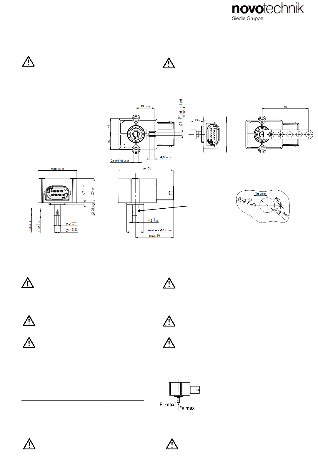
3.1 Maße / Dimensions
Seite / Page 2
RSA-3200 Gebrauchsanleitung
RSA-3200 User Manual
3 Instructions for Installation
Caution! The sensor must not be opened at any time!
At cleaning, steady pressure water (pressure wash)
on the shaft exit has to be avoided!
When used outdoors, the sensor should preferably be installed
with shaft pointing downwards!
3.5 Connector Outlet
6-pin MQS connctor, coding A, tinned contacts according to
drawing AMP-114-18063-126, index A1
(mating connector: AMP order No. 1-967616-1)
The specified protection class is valid only when plugged in.
3.4 Zulässige Wellenbelastung / Permitted shaft load
3.5 Steckerabgang
6-poliger MQS-Stecker, Kodierung A, verzinnte Kontakte nach
Zeichnung AMP-114-18063-126, Index A1
(Gegenstecker: AMP Bestell-Nr. 1-967616-1)
Die angegebene Schutzart gilt nur im gesteckten
Zustand.
Bestellcode
Ordering
code
radial F
rmax.
axial F
amax.
RSA
-32__-___-___-___
50
N
40 N
Wellenmarkierung
Shaft marking
Mit montiertem Hebel Z-RSA-M01 (optionales Zubehör)
With mounted lever arm Z-RSA-M01 (optional accessories)
Vorschlag Bohrbild
Recommended hole pattern
2x Ø4,3 oder/or 2x M4
3.2 Zentrierung
Es wird empfohlen, den Zentrierdurchmesser Ø 18 -0,05 mm
zur Sensoraufnahme und die Indexnut 3 +0,07 mm zur
radialen Ausrichtung zu nutzen.
Die Sensormontage soll möglichst kraftfrei, d.h. ohne
Vorspannung, erfolgen.
Vorsicht! Nichtfluchtender Einbau des Sensors
in Bezug auf die Antriebswelle kann zu einer Reduktion
der Lebensdauer führen!
3.3 Befestigung
Sensor: 2x Zylinderschraube M4, Anzugsmoment
200 … 300 Ncm, Abstand 32 ± 0,15 mm.
Vorsicht! Abweichende Befestigung kann zu
gefährlichen Zuständen führen.
Wellenankopplung:
Vorsicht! Fehlender Formschluss zur Wellen-
abflachung kann zu gefährlichen Zuständen führen.
Der optionale Anlenkhebel wird über einen Spannstift D=2 mm
EN ISO 8752 auf der Welle fixiert . Die Verwendung in
sicherheitsrelevanten Anwendungen muss
applikationsspezifisch bewertet werden.
3.2 Centering
It is recommended to use the centering diameter Ø 18 -0.05 mm
for sensor mounting and the indexing groove 3 +0.07 mm for
radial alignment.
The sensor should be preferably assembled free of force so that
any preload is avoided.
Caution! Misaligned installation of the sensor in relation
to the drive shaft can result in a reduction of life time!
3.3 Fastening
Sensor: 2x cylinder screw M4, tighting torque 200 ... 300 Ncm,
distance 32 ±0.15 mm.
Caution! Deviating fastening can lead to dangerous
states.
Shaft coupling:
Caution! Missing form-fitting to the shaft flattening can
lead to dangerous states.
The optional lever arm is fixed on the shaft via a locking pin D= 2
mm EN ISO 8752. The use in safety related applications must
be evaluated for specific applications.

P/N: 403001638_05 Änderungen vorbehalten / subject to change 2022/03 Seite / Page 3
RSA-3200 Gebrauchsanleitung
RSA-3200 User Manual
Stecker
Plug
Signal
Signal
PIN 1
Versorgung
Ub 1
Supply 1
PIN 2
GND 1
PIN 3
Signalausgang 2
Signal
output 2
PIN 4
Signalausgang 1
Signal
output 1
PIN 5
GND 2
PIN 6
Versorgung
Ub 2
Supply 2
Stecker
Plug
Signal
Signal
PIN 1
Versorgung
Ub
Supply
PIN 2
GND
PIN 3
nicht belegt
not
assigned
PIN 4
Signalausgang
Signal
output
PIN 5
nicht belegt
not
assigned
PIN 6
nicht belegt
not
assigned
Stecker
Plug
Signal
Signal
PIN 1
Versorgung
Ub
Supply
PIN 2
GND
PIN 3
Signalausgang 2
Signal
output 2
PIN 4
Signalausgang 1
Signal
output 1
PIN 5
5 V: GND
12/24 V: nicht belegt /
not assigned
PIN 6
5 V: Versorgung
Ub / supply
12/24 V: nicht belegt /
not assigned
Teilredundant / partly redundant
RSA-32_ _ -7_ _ -_ _ _-521
Einkanalig / single Mehrkanalig / redundant
4.2 Anschlussbelegung / Connection assignment
Vollredundant / fully redundant
RSA-32_ _-8_ _ -_ _ _-521
Single / single
RSA-32_ _ -6_ _ -_ _ _-521
4.1 Output signal
Output characteristic A (standard):
RSA-3201/3202: Shaft marking (flattening) or lever arm is
pointing toward the connector outlet => near electrical center
position
Output characteristic B (180° offset):
RSA-3221/3222: Shaft marking (flattening) or lever arm is
pointing with a 180° offset to the connector outlet => near
electrical center position
4.1 Ausgangssignal
Kennlinienausrichtung A (Standard):
RSA-3201/3202: Wellenmarkierung
(Abflachung) bzw. Hebel zeigt in Richtung
Steckerabgang => Kennlinienmitte
Kennlinienausrichtung B (180° gedreht):
RSA-3221/3222: Wellenmarkierung
(Abflachung) bzw. Hebel zeigt um 180°
verdreht zum Steckerabgang
=> Kennlinienmitte
Kabelbruch oder Verpolung der Anschlüsse kann
zu unsicheren Zuständen führen ! Cable break or reversion of connections can lead to
unsafe states
Spannungsausgang /
Voltage Output
Bestellcode
Ordering code
Versorgung
Supply voltage
Stromaufnahme pro Kanal
Current
draw per channel
Lastwiderstand
Load
Signal bei Kabelbruch
Output at cable break
RSA
-32__-___-2__-___
5 VDC (4,5 … 5,5 VDC)
typ. 12 mA ohne Last
typ. 12 mA w/o load
≥ 5 k
Ω
(Pulldown
)
Break GND: > 95 % Ub
Break
Ub: < 5%
Ub
RSA
-32__-___-34_/35_-
___
12/24 VDC (8 … 34 VDC)
≥ 10 k
Ω ≤ 100 kΩ (
Pulldown)
< 100 mV
Stromausgang /
Current Output
Bestellcode
Ordering
code
Versorgung
Supply voltage
Stromaufnahme pro Kanal
Current draw per channel
Bürde
Burden
Signal bei Kabelbruch
Output at cable break
RSA
-32__-___-32_-___
12/24 VDC (8 … 34 VDC)
typ. 12 mA ohne Last
typ. 12 mA w/o load
≤ 13 V: 10 ... 250 Ω
> 13 V: 10 ... 500 Ω
< 3,5 mA
4 Analoge Schnittstellen / Analog Interfaces

P/N: 403001638_05 Änderungen vorbehalten / subject to change 2022/03
5 Elektrische Daten CAN-Schnittstelle 5 Electrical data CAN Interface
Seite / Page 4
RSA-3200 Gebrauchsanleitung
RSA-3200 User Manual
Stecker
Plug
Signal
Signal
PIN 1
Versorgung
Ub
supply
PIN 2
GND
PIN 3
CAN_H
PIN 4
CAN_L
PIN 5
CAN_L
PIN 6
CAN_H
5.4 Anschlussbelegung / Connection assignment
Bestellcode
Ordering
code
Versorgung
Supply
voltage
Leistungsaufnahme ohne Last
Power drain w/o
load
CANopen
: RSA-32__-214-6__-521
CAN SAE J1939: RSA
-32__-214-J__-521
12/24 VDC (8 … 34 VDC)
Bordnetz /
vehicle supply
≤ 0,4 W
5.3 Ausgangssignal
Kennlinienausrichtung: Wellenmarkierung zeigt in Richtung
Steckerabgang => Kennlinienmitte
5.1 Output signal
Output characteristic: Shaft marking is pointing toward the
connector outlet => electrical center position
5.2 CAN SAE J1939 Schnittstelle
Die Beschreibung der CAN SAE J1939 Schnitt-
stelle (…CAN_SAEJ1939_Detail) ist zum
Download auf der Novotechnik Homepage unter
Downloads/Gebrauchsanleitungen verfügbar
=> Klick auf RSA-3200
5.2 CAN SAE J1939 Interface
The description of CAN SAE J1939 interface
(…CAN_SAEJ1939_Detail) can be downloaded
from Novotechnik website, see Downloads/Operating
manuals => Click on RSA-3200
5.1 CANopen Schnittstelle
Die Beschreibung der CANopen Schnittstelle
sowie das elektronische Datenblatt (EDS) sind
zum Download auf der Novotechnik Homepage
unter Downloads/Gebrauchsanleitungen
verfügbar. => Klick auf RSA-3200
5.1 CANopen Interface
The description of CANopen interface and the
electronic data sheet (EDS) can be downloaded from
Novotechnik web site, see Downloads/Operating
manuals. => Click on RSA-3200
RSA-32__-___ -6__-___
RSA-32__-___-J__-___ Geschirmte oder ungeschirmte Anschlusskabel können verwendet
werden.
Bei geschirmtem Kabel: Abschirmung des Anschlusskabels an
GND bzw. Minuspol der Batterie anschließen.
Twisted-Pair-Kabel (STP) wird empfohlen !
It is possible to use shielded or unshielded cables.
When using shielded cable: Connect cable shielding to GND or to
the negative pole of the battery
Twisted pair cable (STP) is recommended !

P/N: 403001638_05 Änderungen vorbehalten / subject to change 2022/03
6.1 Intended use, conformity
The rotary position measuring system in a fully
redundant version can be used for measuring rotary
positions of machine elements that comply to the special
requirements of safety related applications.
The use of the transducer in a safety related application
must be judged and validated by the system integrator
according to the criteria of DIN EN ISO 13849-1.
In a 2-channel-architecture (2oo2D) this is possible up to
Category 3 / Performance Level d according to DIN EN
ISO 13849.
6.1 Einsatzbereich, Konformität
Das Winkelmesssystem in vollredundanter Ausführung
kann zur Positionserfassung von Maschinen-
elementen, welche den besonderen Anforderungen
von sicherheitsgerichteten Applikationen genügen,
eingesetzt werden.
Der Einsatz des Winkelaufnehmers in einer
sicherheitsbezogenen Applikation muss vom
Systemintegrator nach den Kriterien der DIN EN ISO
13849-1 bewertet und validiert werden.
In einer zweikanaligen Architektur (2oo2D) ist dies bis
Kategorie 3 bzw. Performance Level d gemäß DIN EN
ISO 13849-1 möglich.
6.2 Relevante Normen
DIN EN ISO 13849-1
2006/42/EG
Beispiel: System mit einer Architektur 2oo2D
empfohlen für Kategorie 3
Der Winkelaufnehmer ist kein Logikelement gemäß
Maschinenrichtlinie 2006/42/EG, Anhang IV, Punkt 21.
6.2 Relevant Directives
DIN EN ISO 13849-1
2006/42/EG
Example: System 2oo2D recommended for Category 3
The rotary position transducer is no logical element acc.
To machinery directive 2006/42/EG, Attachment IV,
Chapter 21.
6 Erweiterte Kenndaten zum Einsatz des
Winkelaufnehmers als Subsystem in
sicherheitsrelevanten Applikationen
Legende
imVerbindungsmittel
c Kreuzvergleich z.B. durch Bildung eines
Summensignals
I1, I2 Eingabeeinheiten →Winkelaufnehmer RSA
L1, L2 Logik
m Überwachung
O1, O2 Ausgabeeinheiten (Aktoren, ..)
Legend
imConnection
c Cross comparison, for example by generation of a
sum of both signals
I1, I2 Input units
→
transducer RSA
L1, L2 Logic unit
m Surveillance
O1, O2 Output units (actuators, ..)
I1 L1 O1
imim
m
I2 L2 O2
imim
m
c
Winkelaufnehmer RSA-3200
redundante Ausführung
Rotary transducer RSA-3200
redundant version
6 Extended data for the use of the sensor as a
subsystem in safety relevant applications
This chapter is only valid for analog models
with 2 crossed outputs and activated diagnosis !!
Dieser Abschnitt gilt nur für analoge Varianten
des Winkelsensors mit 2 gekreuzten
Sensorausgängen und aktivierter Diagnose !!
RSA-3200 Gebrauchsanleitung
RSA-3200 User Manual
Seite / Page 5

P/N: 403001638_05 Änderungen vorbehalten / subject to change 2022/03
6.3 Projektierung
6.3.1 Sicherheitsfunktion
Die Sicherheitsfunktion dieses Winkelaufnehmers ist
die Messung der Winkelposition zwischen der
Winkelaufnehmerwelle und dem Winkelaufnehmer-
gehäuse.
Das jeweilige Ausgangssignal hat einen linearen Verlauf
über der relativen Winkelposition innerhalb des
elektrisch definierten Bereiches des Winkelaufnehmers.
6.3.2 Sichere Zustände
a. Fehlerloser Normalbetrieb
Ein sicherer Zustand liegt vor, wenn die
Ausgangskennlinien beider Ausgangskanäle im
definierten gültigen Bereich liegen (s. Datenblatt).
b. Sicherer Ausfall (safe failure) / Diagnose
Jeder Kanal des Sensors verfügt über ein internes
Diagnosesystem zur Erkennung von diversen internen
Fehlern oder Verlust des Positionsgebers (Magnet). Wird
ein interner Fehler erkannt, so wechselt das
Ausgangssignal in den Diagnosebereich:
Ratiometrischer Ausgang < 2% Versorgungsspg. Ub
Stromausgang < 3,5 mA
Spannungsausgang < 100 mV
c. Sicherer Ausfall (safe failure) durch Bewertung
des Summensignals im Steuergerät
Durch Kreuzvergleich (Summenbildung beider Signale)
können weitere Fehler erkannt werden (Gleichtaktfehler).
Für die Bewertung des Summensignals ist eine
Toleranzgrenze festzulegen, welche
applikationsspezifisch ermittelt werden muss.
Für Messwinkel 360°:
Der Übergang von 360 zu 0° bzw. 0 zu 360° ist speziell
zu plausibilisieren, da hier ein abweichendes
Summensignal bestehend aus 2x minimalen bzw.
2x maximalen Einzelsignalen auftreten kann.
6.3.3 Unsichere Zustände
Gefährlicher unentdeckter Ausfall (dangerous
undetected failure)
Ein gefährlicher unentdeckter Fehler liegt vor, wenn
beide Ausgangssignale innerhalb der definierten
Kennlinien einen Fehler aufweisen, welcher nicht durch
o.g. Methoden diagnostiziert werden kann
(Gegentaktfehler).
Stromschnittstelle:
Beim Kurzschluss beider Ausgangsleitungen
ist das Summensignal der gekreuzten
Kennlinien im definierten gültigen Bereich
(Signal entspricht Kennlinienmitte). Dadurch ist
dieser Fehlerfall nicht zu diagnostizieren und ist
kundenseitig zu vermeiden oder zu bewerten.
6.3.4 Konfiguration der Logikeinheiten
Die Logikeinheiten müssen die Ausgangskreise des
Winkelaufnehmers auswerten.
Die Logikeinheiten müssen mindestens dem
Performance Level des Systems entsprechen.
6.3 Projecting
6.3.1 Safety function
The safety function of this transducer is the
measurement of the angular position between the
transducers shaft and its housing.
Each output signal has a linear relationship across the
relative angular position in-between the electrically
defined range of the transducer.
6.3.2 Safe states
a. Error free normal operation
A safe state is present when the output signals of both
channels are inside the valid output range (see data
sheet)
b. Safe failure / Diagnosis
Every sensor channel has an internal diagnostics to
detect various internal malfunctions or loss of position
marker (magnet). When an an error is detected, the
output signal changes into the diagnostic range:
Ratiometric output < 2% supply voltage Ub
Current output < 3.5 mA
Voltage output < 100 mV
c. Safe failure by evaluation of both channels in
ECU
By cross comparison (sum of channel 1 and channel
2), further errors can be detected (common mode
error). For the evaluation of the sum signal, a tolerance
limit has to be defined that has to be determined
application specific.
For measuring range 360°:
The transition from 360 to 0° or 0 to 360° must be
specifically checked for plausibility as a different sum
signal consisting of 2x minimum or 2x maximum single
signals can occur.
6.3.3 Unsafe states
Dangerous undetected failure
A dangerous undetected failure is present when both
output signals are along the defined output curves and
still have an error or deviation that cannot be detected
by the above described methods (reverse mode error).
Current Interface:
If both output lines are short-circuited, the sum
signal of the crossed output characteristics is
within the defined valid output range (signal
corresponds to electrical center position).
So, this error case cannot be detected and
has to be avoided or evaluated by the
customer.
6.3.4 Configuration of Logical Units
The logical units must process the output curcuits of
the transducer.
The logical units must at minimum comply to the
intended Performance Level of the system.
RSA-3200 Gebrauchsanleitung
RSA-3200 User Manual
Seite / Page 6

P/N: 403001638_05 Änderungen vorbehalten / subject to change 2022/03
6.4 Annahmen für Sicherheitsbetrachtung
Bei der Durchführung der Sicherheitsbetrachtungen
(FMEAs, FMEDA, etc.) wurden folgende Annahmen
zugrunde gelegt:
•Ausfallraten sind konstant
•Abnützung der mechanischen Teile, Ausfallraten von
externen Stromversorgungen und Mehrfachfehler
wurden nicht betrachtet
•Die mittlere Umgebungstemperatur während der
Betriebszeit beträgt 40 °C (104 °F)
•Die Umweltbedingungen entsprechen einer
durchschnittlichen industriellen Umgebung
•Die Gebrauchsdauer des Sensors liegt im Bereich
von 8 bis 12 Jahren (IEC 61508-2:2010, 7.4.9.5,
Anmerkung 3)
•Die die Sensordaten auswertende Logik bewertet die
Plausibilität des Ausgangssignales jedes einzelnen
Kanals sowie die Summe beider Ausgangsignale
•Die Grenzwerte für den maximal akzeptablen Fehler
des Einzelsignales sowie der Summe der Kanäle
wurden in der FMEDA-Excel-Datei (auf Anfrage) als
vom Kunden variierbar angelegt, um die spezifisch für
die jeweilige Applikation im Ergebnis MTTFd- und
DCavg-Werte zu erhalten.
6.6 Wiederkehrender Funktionstest
Der wiederkehrende Funktionstest dient dazu, die
Sicherheitsfunktion zu überprüfen, um mögliche, nicht
erkennbare gefährliche Fehler aufzudecken. Die
Funktionsfähigkeit des Messsystems ist deshalb vom Betreiber
in angemessenen Zeitabständen nach DIN EN ISO 13849 zu
prüfen.
6.6.1 Durchführung des Funktionstests
Die Prüfung ist so durchzuführen, dass die einwandfreie
Sicherheitsfunktion im Zusammenwirken aller Komponenten
nachgewiesen wird.
Der Winkelaufnehmer ist in zuvor bekannte Positionen (Welle
relativ zu Gehäuse) zu bringen und die Korrektheit des
jeweiligen Messwertes zu prüfen.
Die bei dem Test verwendete Methode muss benannt und
deren Eignungsgrad spezifiziert werden. Die Prüfung ist zu
dokumentieren.
Verläuft der Funktionstest negativ, muss das gesamte
Messsystem außer Betrieb genommen und der Prozess durch
andere Maßnahmen im sicheren Zustand gehalten werden.
6.5 Verhalten im Betrieb und bei Störungen
Bei festgestellten Fehlern muss das gesamte Messsystem
außer Betrieb genommen und der Prozess durch andere
Maßnahmen im sicheren Zustand gehalten werden.
Wird aufgrund eines festgestellten Fehlers der
Winkelaufnehmer ausgetauscht, so ist dies dem Hersteller zu
melden (inklusive einer Fehlerbeschreibung).
6.4 Presumptions for safety examinations
During processing of the safety examinations (FMEAs,
FMEDA, etc.), the following presumptions were met:
•Failure rates are constant
•Wear on mechanical parts, failure rates of external
power supplies and multiple faults were not taken into
account
•The mean temperature during working time is 40 °C
(104 °F)
•The environmental conditions correspond the ones
from an average industrial environment
•The useage time of the sensor lies in the range of 8 to
12 years (IEC 61508-2:2010, 7.4.9.5 remark 3)
•The logic unit that processes the sensor‘s data checks
for the plausibility of each channel as well as the total
of both channels.
•The limit values for the max. acceptable error of a
single channel and the total of both channels are in the
FMEDA Excel document (on request) adjustable by the
customer to the needs of his application, resulting in a
variation of resulting MTTFd and DCavg values.
6.6 Periodic Function Verification
The periodic function verification serves for checking the safety
function in order to find possible, non observable dangerous
failures. Hence the functionality of the transducer is to be
checked periodically by the user in appropriate time periods
acc. to DIN EN ISO 13849.
6.6.1 Processing of the Function Verification
The test is to be processed in a way that the faultless safety
function in the cooperation of all components can be validated.
The transducer is to positioned in previously known positions
(shaft relative to housing) and the correctness of the
corresponding output is to be checked. The method used in the
test must be stated and its suitability has to be specified. The
test must be documented.
If the funtional test shows negative results, the whole system
has to be taken out of function and the process has to be kept
in safe condition by other methods.
6.5 Behaviour during operation and during disturbances
When errors are found, the complete system has to be taken
out of use and the process has to be kept in safe condition by
lternative means.
When the transducer is taken out of the system
(Replacement) the manufacturer needs to be informed and
the transducer needs to be sent to the manufacturer. A failure
description needs to be issued.
6.7 Gebrauchsdauer
Nach 8 bis 12 Jahren werden sich die Ausfallraten der
elektronischen Bauelemente vergrößern, wodurch sich
die daraus abgeleiteten PFD- und PFH-Werte ver-
schlechtern (IEC 61508-2:2010, 7.4.9.5, Anmerkung 3).
6.7 Useage Time
After 8 to 12 years, the failure rates of electronic
components will increase. Thus, the derived PFD- und
PFD values will worsen (IEC 61508-2:2010, 7.4.9.5,
remark 3).
RSA-3200 Gebrauchsanleitung
RSA-3200 User Manual
Seite / Page 7
P/N: 403001638_05 Änderungen vorbehalten / subject to change 2022/03
6.8 Sicherheitstechnische Kennzahlen
Die Ausfallraten werden durch eine FMEDA nach DIN
EN ISO 13849-1 ermittelt. Den Berechnungen werden
Bauelementeausfallraten nach DIN EN ISO 13849-1
bzw. SN 29500 zugrunde gelegt.
Alle Zahlenwerte beziehen sich auf eine mittlere
Umgebungstemperatur während der Betriebszeit von
40 °C (104 °F).
Für eine höhere durchschnittliche Temperatur von 60
°C (140 °F) sollten die Ausfallraten erfahrungsgemäß
mit einem Faktor von 2,5 multipliziert werden. Ein
ähnlicher Faktor gilt, wenn häufige
Temperaturschwankungen zu erwarten sind.
Die Berechnungen stützen sich weiterhin auf die im
Kapitel "Projektierung" genannten Hinweise und
Annahmen.
Die Sicherheitsbewertung selbst kann nur vom
Anwender durchgeführt werden, indem die
bereitgestellte Berechnungsgrundlage auf die
Applikation hin parametriert wird.
Die Ergebnisse der Berechnungen von Novotechnik
sind hierfür auf Anfrage erhältlich. Bitte wenden Sie
Deutschlands an Ihren zuständigen Repräsentaten.
6.8 Safety relevant data
The sensor‘s failure rates are calculated using an
FMEDA acc. to DIN EN ISO 13849-1. The underlying
components fit rates are taken from DIN EN ISO
13849-1 and SN 29500.
All values relate to a medium ambient temperature
during operation of 40 °C (104 °F).
For a higher ambient temperature of 60 °C (140 °F)
these failure rates have to by multiplied by a factor of
2,5 by experience. A similar factor should be used, if
frequent temperature changes are to be expected.
Furthermore, the calculations relate to the
presumptions in chapter „Projecting".
The safety evaluation itself can only be done by the
user of the component by parametrisation of the
calculation basis from Novotechnik to the
applications needs.
The results of the calculations from Novotechnik are
available on request. Please ask your local distributor
RSA-3200 Gebrauchsanleitung
RSA-3200 User Manual
Seite / Page 8
7 Bestellangaben / Ordering Specifications
RSA - 32_ _- _ _ _ - _ _ _ - 521
Mechanische Ausführung
Mechanical configuration
3201/3221 shaft version
3202/3222 with mounted lever
Elektrische Schnittstelle
Electrical interface
2_ _ ratiometric 5V
32 _ current output
34_ / 35_ voltage output
6_ _ CANopen
J_ _ CAN SAE J1939
Elektrischer Anschluss
Electrical connection
521 connector AMP MQS
Elektrischer Messbereich
Electrical measuring range
214 digital 14 bit resolution
6_ _ analog single
7_ _ analog partly redundant
8_ _ analog fully redundant
_03 … _36 30 … 360°
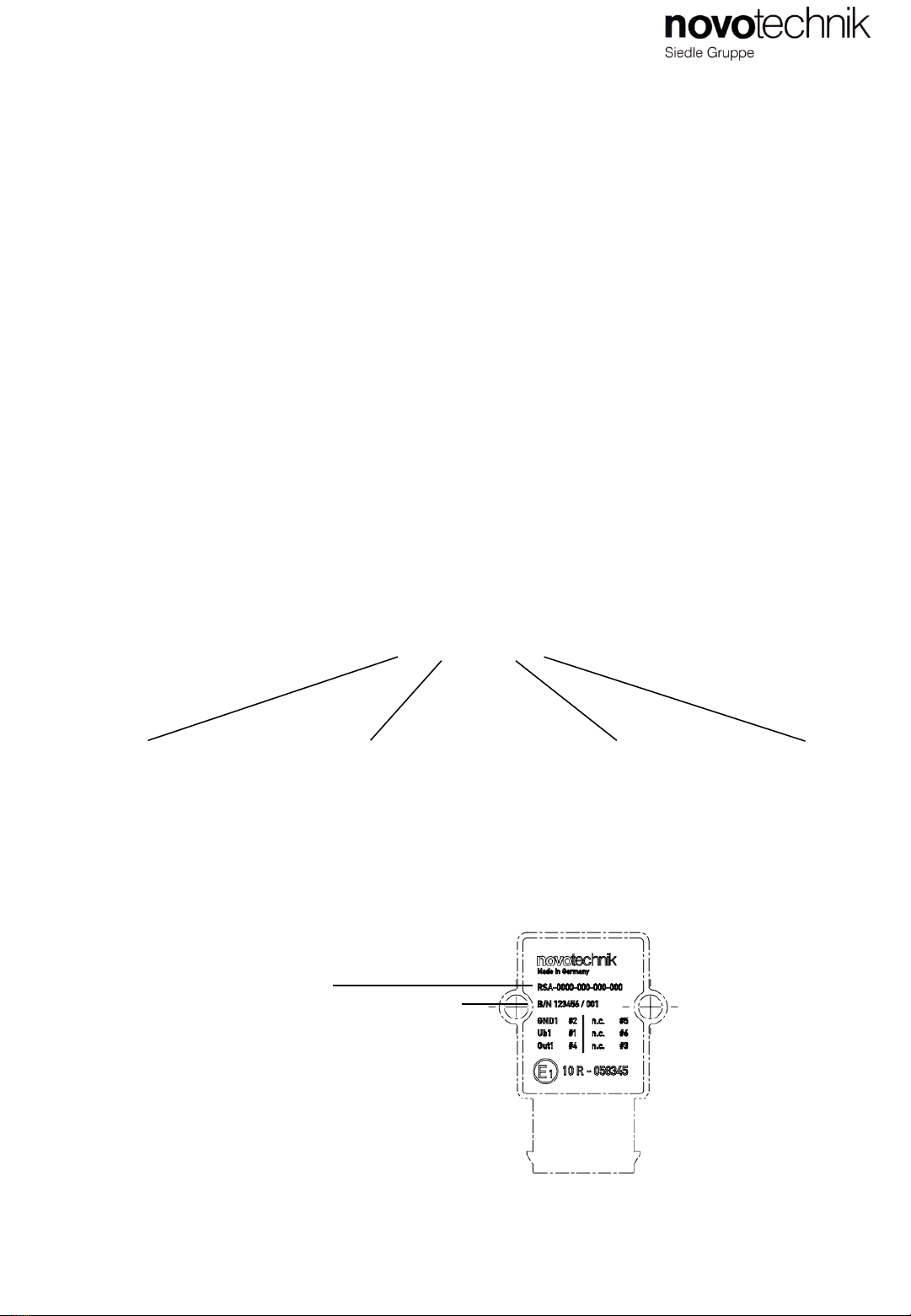
8 Produktidentifikation / Product Identification
Laserkennzeichung
Laser marking
Bestellcode
Ordering code
Seriennummer bestehend aus
Fertigungscharge/fortlaufende Nr.
Serial No. consisting of
Batch No./consecutive number
Other Siedle Accessories manuals


