Continuum Cobra S User manual

OWNERS MANUAL
AUDIBLE SCIENCE

audible scienceaudible science
Congratulations on choosing the Cobra tonearm.
The Cobra is a totally new design in tonearm technology
which has been developed by a team of dedicated music
lovers with qualifications in advanced engineering and
design, assisted by some of the most advanced computer
aided design software in the market today.
We ask that you take the time to read this manual carefully
to ensure that you not only enjoy optimum sound quality
from your Cobra, but also understand the care and
maintenance procedures required to keep your Cobra in
as-new condition for many years to come.
If you have any questions in reference to any part of your
Cobra at any time in the future, please feel free to contact
your Continuum Consultant for assistance.
Your Authorised Continuum Consultant is:
Serial Number:
Date of Manufacture:
AUDIO LABORATORIES PTY LTD
SERIOUSLY ADDICTIVE
by
page 2

audible scienceaudible science
CAUTION
Refer servicing to
qualified personnel only.
Precautions
On Safety
Should any solid object or
liquid fall into the tonearm,
have it checked by your Factory
Authorized Consultant
On Placement
• Place the unit in a location with
adequate ventilation to prevent
heat buildup and prolong the life
of the unit.
• Do not place the unit near heat
sources, or in a place subject to
direct sunlight, excessive dust or
mechanical shock.
• Do not place anything near
the unit that might create RF
interference.
On Operation
Before connecting to phono
stage components, be sure to
follow component manufacturers
intructions.
On Cleaning
Clean tonearm, and controls with
a soft cloth slightly moistened
with a mild detergent solution. Do
not use any type of abrasive pad,
scouring powder or solvent such
as alcohol or benzine.
If you have any questions or
problems concerning your
Cobra tonearm, please contact
your Continuum Authorized
Installation Consultant
TABLE OF CONTENTS
OUR DESIGN PHILOSOPHY ..................6
DESIGN FEATURES
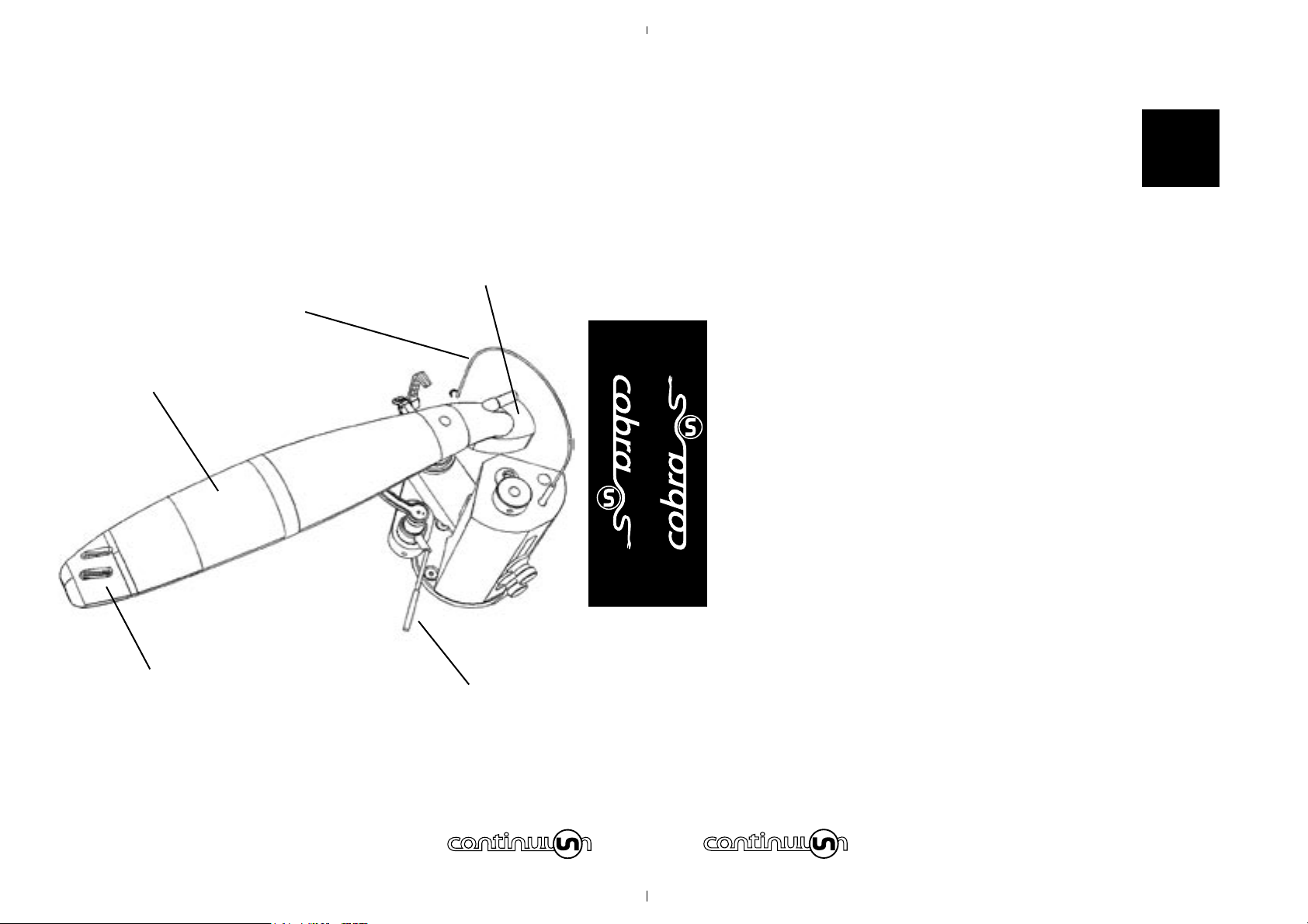
Arm Wand ............................................ 8
Headshell ............................................. 8
Fingerlift .............................................. 10
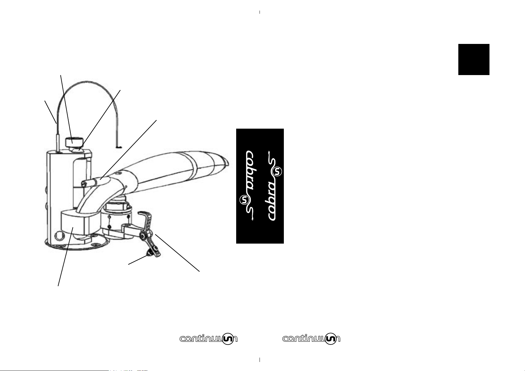
Arm Lifter ............................................. 10
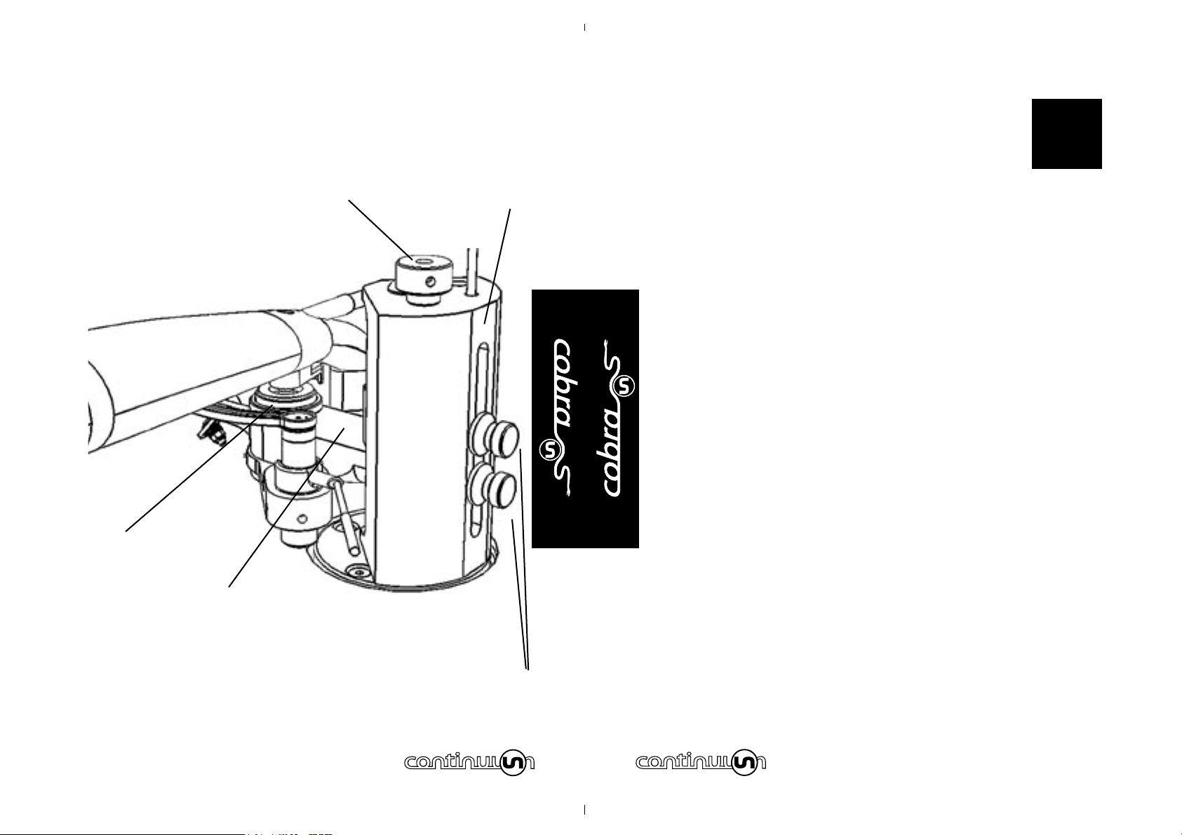
Counterweight ...................................... 10
Vertical Bearing Motion ........................... 12
Horizontal Bearing Motion ....................... 14
Azimuth Adjustment .............................. 14
Stylus Rake Angle (SRA) or (VTA) ............ 16
Overhang Adjustment ............................ 20
Anti Skate or Bias Adjustment ................. 22
INSTALLATION
Why Set up is Critical ............................. 24
Installation & Set up .............................. 28
Positioning Central Tower on Turntable ..... 30
Distance of Spindle to Cross Arm Pivot ..... 34
VTA & SRA Set up .................................. 36
Mounting the Cartridge ........................... 38
Mounting & Balancing the Arm ................ 38
Connecting and Adjusting Anti Skate ........ 42
Setting the Azimuth ............................... 48
OWNER CARE & MAINTENANCE
Routine ................................................ 54
Specifications ........................................ 56
THE COBRA’S DESIGN HISTORY ..........
TABLE OF
CONTENTS
page 4

audible scienceaudible science
AIM FOR PERFECTION
Perfection, as a design concept, is not easily
defined. It maybe easier explained by listing the rules
it cannot be constrained by - budget, time, materials,
tradition, aesthetics, fashion or dogma.
AIM FOR PERFECTION, means we strive remove all the
constraints listed above, allowing us to concentrate
wholly on creating a product whose only constraint is
perfection itself. How close we get is for others to judge,
but we see no point aiming for anything less.
The Cobra is a perfect example of this design philosophy,
and was created because, after looking closely at the
state-of-the-art, we believed it could be better.
Any future products from Continuum Audio Labs will
follow this same philosophy - if we believe it can be
better, we will build it. If we believe we cannot improve
it, we will enjoy and happily recommend the state-of-the-
art product. Because, our ultimate aim is the pursuit of
perfect sound reproduction.
OUR
DESIGN
PHILOSOPHY
page 6
COBRA TONEARM ASSEMBLY
Arm lifter
Integrated headshell
Arm wand
“Heart-shaped” counterweight
Arm wire guide

audible scienceaudible science
COBRA DESIGN FEATURES
The Cobra represents the single biggest
breakthrough in performance of tonearm technology since
the groundbreaking designs of the 1980’s that changed the
way LP’s were played.
THE ARM WAND
Unique Monocoque construction using advanced fibre and
resin technology proprietary to Continuum Audio Labs.
The shape of the arm wand is optimised to reduce the
resonances inherent in the LP playback mechanism. There
is no need to apply additional damping material to the
Cobra as the polymer/fibre technology is by its very nature
extremely well damped.
THE HEADSHELL
The Cobra headshell is one piece with 12.5mm of
adjustment accepting standard M2.5 cartridge screws.
Please note: the depth of screws required is longer
than standard at 15mm minimum for cartridges with
integrated threads.
PARTS OF
YOUR COBRA
page 8

audible scienceaudible science
COBRA DESIGN FEATURES CONT.
THE FINGERLIFT
The Cobra Finger lift is extended to the right of the head
shell at an angle designed to allow safe operation of manual
cueing. It is recommended that one use extreme caution
when cueing manually as stylus damage can result from
minor errors in handling. We recommend you use the arm
lifter to ensure safe operation of cartridge cueing.
THE ARM LIFTER
The arm lift is a standard industry format using silicon gel
damping. The height of the arm lifter is adjustable using
a standard metric allen wrench (supplied). The arm lifter
must be adjusted to suit the desired range of SRA or VTA
adjustment and relationship to turntable platter level.
THE COUNTERWEIGHT
The Cobra uses a neutral balance design to minimise
variations in tracking force over warps. Tracking force
remains constant when the arm is moved vertically.
To achieve neutral balance, the center of mass of the front
end of the arm, the vertical pivot, and the tail end of the
arm should lie on a straight line.
PARTS OF
YOUR COBRA
page 10
VTA locking thumb screws
Vertical sliding cross arm
VTA fine vertical adjustment knob
Azimuth adjustment “Swash Plate”
Vertical VTA vernier

audible scienceaudible science
COBRA DESIGN FEATURES CONT.
THE COUNTERWEIGHT cont.
In addition, to minimize warp wow (pitch
changes as the stylus rides up and down over record
warps), the arm’s vertical pivot should be at the same
height as the record surface.
The Cobra uses a “heart like” shaped counterweight,
optimised for reduction of vibration.
To balance the arm a user uses a series of weights
which are added or subtracted from the underside of the
counterweight to get the cartridge into the correct zone.
An 8 Gram adjustable screw at the rear of the arm allows
for microscopic adjustments in the tracking force once
the cartridge is close to the correct weight range for the
counterweights. The counterweight also allows for some
“skewing” adjustment to forces in the azimuth plane.
THE VERTICAL BEARING MOTION
The Primary Pivot is a Precision Sapphire Vee Jewel with
Hardened Steel matching Central pivot. Used in the finest of
aircraft instruments this pivot technology does not require
heavy mass to be positioned over the pivot thus allowing for
exceptional tracking and response to groove modulation.
PARTS OF
YOUR COBRA
page 12

audible scienceaudible science
COBRA DESIGN FEATURES CONT.
THE VERTICAL BEARING MOTION cont.
Secondary Pivot – Azimuth Stabilized with a Hardened Steel
Inverted pivot resting on a man made Sapphire “Swash
Plate”. This secondary pivot plays a crucial role in the
stability of the arm allowing for optimum placement of the
counterweight thus removing inertial problems associated
with alternative stabiliser designs.
THE HORIZONTAL BEARING MOTION
Two precision matched ABEC 7 vertically opposed bearings
with internal damping. Minimises precessional effects in
rotational plane to close to zero.
THE AZIMUTH ADJUSTMENT
Azimuth is adjusted by means of fine threaded Sapphire
Bearing swash plate. This is adjustable with micrometer
accuracy indicated on a clock face engraved on the azimuth
adjuster. Please ensure stylus is at rest when you adjust
azimuth.
Do not attempt to adjust during playback.
It is recommended azimuth is adjusted with a test record
and purpose designed scope or meter.
PARTS OF
YOUR COBRA
page 14

audible scienceaudible science
COBRA DESIGN FEATURES CONT.
THE AZIMUTH ADJUSTMENT cont.
Please contact your Continuum Consultant if
you have any questions regarding these settings.
WARNING: If you use the wrong type of meter you
can destroy a cartridge coil mechanism. Digital
meters are especially prone to causing this “coil
burnout”. If you are unsure of the equipment you
are using to adjust azimuth please contact your
Authorised Continuum Consultant.
STYLUS RACK ANGLE (SRA) OR
VERTICAL TRACKING ANGLE ADJUSTMENT (VTA)
Continuum Audio Labs recognise that the original cutting
lathes used to make the master recordings have varying
degrees of calibration. We note that even minor changes in
SRA or VTA can have significant audible effects.
The Cobra offers the discerning audiophile an easy to adjust
mechanism to extract the last vestiges of performance from
your favourite LP.
To adjust the VTA, two thumbscrews at the rear of the main
arm mount are loosened to free the vertical sliding cross
arm. Then, the user turns the VTA fine vertical adjustment
PARTS OF
YOUR COBRA
page 16

audible scienceaudible science
COBRA DESIGN FEATURES CONT.
STYLUS RACK ANGLE (SRA) OR VERTICAL
TRACKING ANGLE ADJUSTMENT (VTA) cont.
knob clockwise to raise the arm pivot and counter clockwise
to lower the arm pivot.
Once the desired setting is reached the thumbscrews
are gently tightened to lock the arm mechanism in place
precisely. This system prevents any grub screw marking of
the main sliding shaft system. It is also triangulated in 3
planes to maximise stiffness.
This is adjustable during playback to dial-in your favourite
setting for various thickness of LP’s.
A broad scale vertical Vernier indicator is located on the
main arm support tower which is further enhanced by a fine
scale micrometer dial on the adjustment knob located at
the top of the main arm support tower.
A vertical movement of 4mm in the main pivot represents
1 degree of SRA or VTA change. The Cobra arm design is
based on a standard stylus tip to top of cartridge dimension
of 18mm.
PARTS OF
YOUR COBRA
page 18
Anti Skate mechanism
“Heart-shape” counterweight
Anti Skate weight adjustment
8mm fine weight adjustment
VTA fine vertical adjustment knob
Overhang locking bolt
Arm wire guide

audible scienceaudible science
COBRA DESIGN FEATURES CONT.
STYLUS RACK ANGLE (SRA) OR
VERTICAL TRACKING ANGLE ADJUSTMENT
(VTA) Other cartridge sizes can easily be used but the
majority of modern quality cartridge bodies and stylus
tip dimensions are set at or near a nominal dimension of
18mm.
The Cobra arm is very forgiving of setup errors so will
reward those who “seek the tweak” as well as those
listeners who prefer to “set and forget”.
As a general rule if the VTA is too high the sound will be
“lean and thin” and if the VTA is too low the sound will be
“boomy” and potentially “bass heavy”. This is of course
totally to user preference but will reward those seeking the
maximum from their LP collections.
OVERHANG ADJUSTMENT
The best setting is 221.7 mm (set during installation) but
allowance of 12.5mm adjustment in headshell slots allows
some minor variation in this distance. A single 8mm Socket
Head Cap Screw is tightened to lock the main arm support
mount into the correct location allowing for accurate VTA
adjustment without losing settings for overhang.
PARTS OF
YOUR COBRA
page 20

audible scienceaudible science
COBRA DESIGN FEATURES CONT.
ANTI SKATE OR BIAS ADJUSTMENT
The Cobra allows optimal anti skate force to be increased
from 8-12% of the tracking force across the playing surface
by use of correct geometry of the anti skate lever and the
ability to move the weight along the lever arm with an
additional ability to add or subtract weights.
The Arm wire guide is designed to minimise torque forces
affecting anti skate. We recommend a quality tool such as a
Wally Skater from WAM Engineering or a modulated groove
test disc such as Cardas Test Disc or Omni Disc available
from reputable LP suppliers is used to set antiskate.
CAUTION: In our opinion use of an unmodulated
groove to determine bias adjustment is an inaccurate
method of determining anti-skate force due to the
absence of modulated groove drag force .
OPERATING
YOUR COBRA
page 22

audible scienceaudible science
page 24
INSTALLATION & SETUP
WHY SETUP IS CRITICAL
If a phono cartridge is not correctly setup, damage can
occur to your precious record collection, and you will
miss out on the incredible realism that good vinyl can
reproduce.
The design of the Cobra tonearm allows for minute
adjustments to be made to ensure the stylus tip is
correctly positioned in all planes.
The positioning of the stylus tip in the spinning record
groove is referred to as tracking ability.
It is defined as the maximum velocity at which the stylus
tip can move back and forth tracing the audio signal
before it starts to skip. A tracking failure is referred to as
mistracking.
Serious mistracking, when the high mass of the stylus
causes it to veer out of control, can permanently damage
a record by altering the signal patterns in the record
groove. Such damage can occur in just one play.
INSTALLING
& TUNING
YOUR COBRA
Cut away view of Cobra
VTA locking thumbscrews
Overhang locking bolt
Cross arm

audible scienceaudible science
page 26
INSTALLATION & SETUP CONT.
WHY SETUP IS CRITICAL The stylus tip
traces the musical signal inscribed in the record groove,
which can contain modulations as small as a millionth of
an inch. Therefore small adjustments to the stylus tip’s
position will alter the sound significantly.
If you are unfamiliar with cartridge setup procedures
please contact your Continuum Audio Labs Authorised
Installation Consultant for assistance.
With the almost ubiquitous nature of the internet there
are many resources available for learning about cartridge
setup.
However we urge caution in following some of the
recommendations found on user groups and bulletin
boards. Some of these tips are not based on sound
engineering principles.
Please refer to manufacturer instructions in all cases
before trying any “tweaks”. Failure to follow manufacturer
instructions can result in a voiding of any warranties.
INSTALLING
& TUNING
YOUR COBRA

audible scienceaudible science
INSTALLATION & SETUP CONT.
INSTALLATION
This Manual is for Factory Authorized Installers and
technically proficient users who are familiar with phono
cartridges and tonearm installation terminology and
concepts.
The main steps of installing the Cobra are:
1. Disassembly to enable mounting to turntable.
2. Installation of the central tower mount.
3. Re-assembly of main arm components
4. Adjustment and lock down of overhang dimension
5. Adjustment of pivot height relative to platter height
7. Installing Cartridge on Wand
8. Installing Wand on pivot assembly
9. Balancing the wand
9. Connecting antiskate string
9. Adjusting of anti skate force
10. Adjustment of azimuth for initial cartridge setup
INSTALLING
& TUNING
YOUR COBRA
page 28
232.81mm
Distance of spindle to central arm tower = 251.60mm
86.95mm
Turntable spindle
Central arm tower

audible scienceaudible science
page 30
INSTALLATION & SETUP CONT.
DISASSEMBLY & ASSEMBLY OF THE COBRA
The Cobra comes to you with the main components
assembled, and needs to be disassembled for installation.
DISASSEMBLY FOR MOUNTING PROCEDURE
Use a 6mm allen key to undo the overhang locking bolt
on the top of the main body. Next, loosen the two VTA
locking thumb screws, and slide the central tower off the
main body and cross arm.
NOTE: take note of how the central tower fits
through the cross arm, for when you have to
reassemble it.
You are now ready to mount the Central Arm Tower
to the turntable.
POSITIONING CENTRAL TOWER ON TURNTABLE -
DISTANCE OF SPINDLE TO CENTRAL ARM TOWER
Once you have marked the center point of the Central
Arm Tower you will need to drill 4 equispaced holes to
bolt the arm mount onto the plinth.
INSTALLING
& TUNING
YOUR COBRA
Central Tower
Cross arm -
Main Body
with Cross arm
slide inside the Main Body
before inserting the Central
Tower into the Main Body
Fully assembled

audible scienceaudible science
page 32
INSTALLATION & SETUP CONT.
DISTANCE OF SPINDLE TO CENTRAL ARM TOWER
We recommend you use 4mm Socket Head Cap Screws
and professionally drill and tap the plinth or armboard to
allow the arm to be bolted directly to the plinth.
The 4 equispaced holes need to be drilled on a 56mm
PCD (Pitch Circle Diameter) to suit M4 screws. We
recommend these 4 holes are drilled cardinally (North
South East West) but depending on your unique
installation these can be drilled in any orientation that
clears infrastructure obstacles.
Note: If the plinth requires a cutout to access a
sub-chassis then the main arm mount requires a
72-80mm hole to be cut to allow for clearance.
Once you have drilled and tapped the required holes you
can bolt the Central Arm Tower down. You are now ready
to place the main arm mount and crossarm with pivot
assembly on to the Central Arm Tower and lock down the
Spindle to Pivot or overhang distance.
INSTALLING
& TUNING
YOUR COBRA
VTA thumbscrews
Vernier scale

audible scienceaudible science
page 34
INSTALLATION & SETUP CONT.
SPINDLE TO MAIN PIVOT DISTANCE (OVERHANG)
Overhang is adjusted by positioning the main pivot in
relation to the turntable spindle.
The Cobra uses an offset crossarm that holds the main
pivot. This crossarm can be rotated in a shallow arc that
allows for variances in turntable plinth designs.
The optimum distance from pivot to spindle is 221.7 mm.
Viewing the platter from above (Plan View) use a metric
ruler to measure from the spindle to the main arm pivot
(located on the crossarm) a distance of 221.70mm.
Next tighten the 8mm Hex Head Overhang Locking Screw
using a 6mm Allen Key. Do not overtighten. This screw
compresses the main arm mount and the main arm body
which holds the crossarm and pivot. Once this screw
is tightened the overhang is firmly set. This setting is
maintained even when you are adjusting the VTA.
INSTALLING
& TUNING
YOUR COBRA
Distance of spindle to cross arm pivot = 221.70mm
Cross arm pivotTurntable spindle

audible scienceaudible science
page 36
INSTALLATION & SETUP CONT.
VTA & SRA SETUP
HOW TO ADJUST VTA AND SRA
At the rear of the main arm mount there are two
thumb screws. These need to be loosened in order for
the crossarm to be raised or lowered using the VTA
adjustment knob at the top of the main arm mount.
There is a broad scale vernier on the rear of the main
arm mount. This is complemented by a dial scale at the
top of the VTA adjustment knob.
Once you have set the main arm pivot at the same level
as the platter you can mark the position on both the rear
vernier and dial scale on the adjustment knob using a
marker pen or coloured nail varnish. Experienced Cobra
users often use different coloured marks to identify
preferred settings for varying thickness LP’s.
Use a ruler edge to sit on the platter and let it protrude
over the edge to line up over the arm pivot (remove the
wand to do this).
INSTALLING
& TUNING
YOUR COBRA
Cobra central arm
bearing cup
Cobraʼs “heart-shaped”
counterweight with
removeable weights
Cross arm pivot

audible scienceaudible science
page 38
INSTALLATION & SETUP CONT.
HOW TO ADJUST VTA AND SRA cont.
Raise or lower the cross arm till the main pivot touches
the edge of the ruler. This is the level point from which to
adjust the VTA up or down.
To tighten the thumbscrews use only light finger force
as these thumbscrews can exert many kilograms of
pressure.
HOW TO MOUNT THE CARTRIDGE
The Cobra headshell is a one piece contruction and
accepts all standard 12.7mm cartridges, MC and MM.
Mount cartridge in the headshell according to the
manufacturers instructions. Use the cartridge mounting
screws supplied with your Cobra.
Do not force or overtorque the M2.5 screws.
Connect the Cartridge pins to the arm wire following the
cartridge manufacturers instructions.
INSTALLING
& TUNING
YOUR COBRA
Cobra one piece headshell
use supplied screws to
mount cartridge
Table of contents
Popular Accessories manuals by other brands

TEKTELIC Communications
TEKTELIC Communications Kona All-in-One Home Sensor Series user guide

Safeguard Supply
Safeguard Supply LRA-D1000 quick start guide

WIKA
WIKA MG-1 operating instructions

GROTHE
GROTHE CALIMA 800 Installation and operating instructions

Intrasonic Technology
Intrasonic Technology V500 Installation and operation instructions

Origin Instruments
Origin Instruments PageBot for Kindle 2 user guide