Sieg SX1P User manual
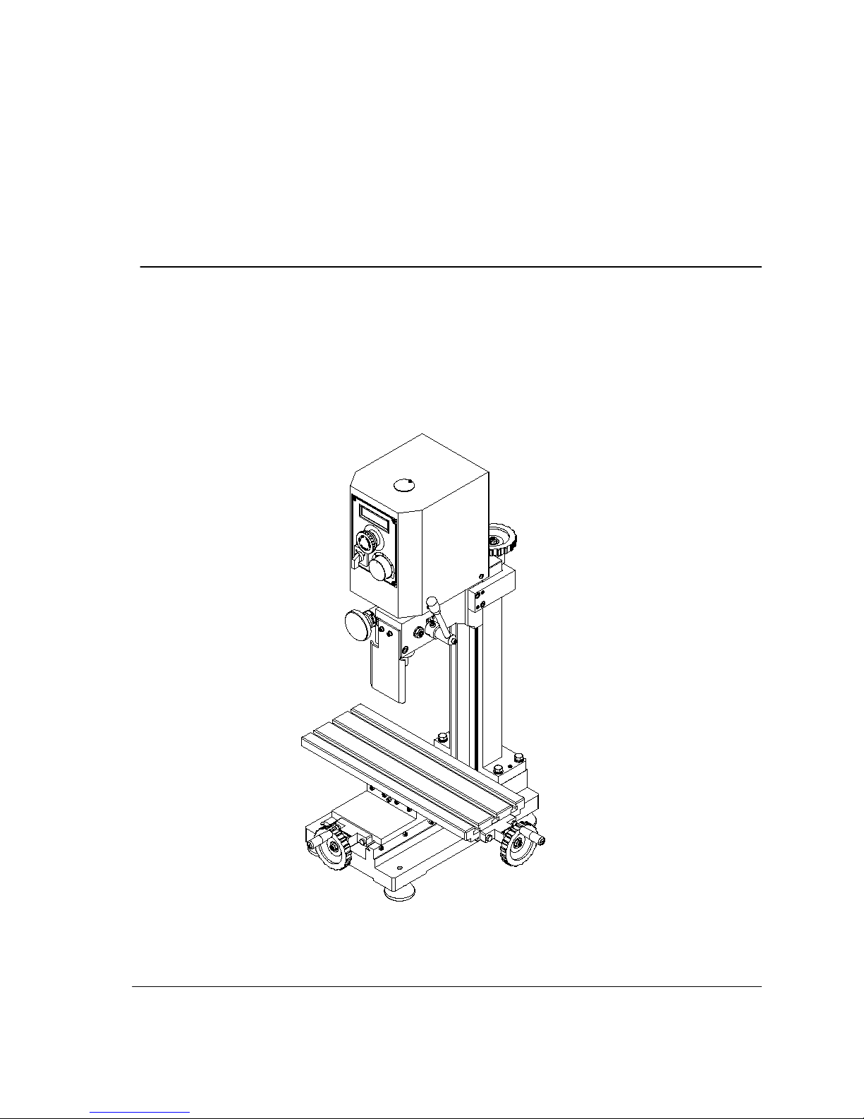
MICRO MILL
Instruction Manual
SX1P
Read all instructions and warning before using this tool

1
CONTENTS
CHAPTER 1 SPECIFICATION
1-1 Machine specification
CHAPTER 2 MACHINE INSTALLATION
2-1 Fundamental locating of the machine
2-2 Preparation before operation
CHAPTER 3 PREVENTION AND MAINTENANCE
3-1 Prevention and maintenance
3-2 Maintenance of cutter and taper shank
3-3 Mechanics lubrication
CHAPTER 4 MACHINE STRUCTURE
4-1 External feature
4-2 Assembly parts
CHAPTER 5 MECHANISM ADJUSTMENT
5-1 Installation and removal of taper shank
5-2 Travel adjustment
5-3 Adjust dip angle of fuselage
5-4 Miter Wedge Adjustment
CHAPTER 6 OPERATION AND NOTICE FOR USE
6-1 Method of operation
6-2 Operation attention
CHAPTER 7 GENERAL SAFETY INSTRUCTION
CHAPTER 8 ELECTRICITY
8-1 Electrical circuit diagram
CHAPTER 9 PACKING LIST

2
Some Safety Features of this Machine
a) Purpose of this machine: This machine is designed for drilling, deep milling
and face milling of small work piece with limit .
If the operator intend to use this machine beyond our design purpose,
please contract the manufacturer or your dealer before operation .
b) The following items is prohibited for this machine
- Operating machine without going through of manual.
- Operating machine without professional training of drilling & milling work.
- Operation machine beyond the design purpose and limit of this machine
- without getting sufficient consultant about safety from manufacturer or our
agent.
- Operating machine without making sure that every safety precaution is
well according to this instruction.
c) Some important safety information.
- The noise level during operation is 70~75dB(A).
- The temperature rang suitable for the operation & storage of this machine
is -20 ~ +40 degree C.
d) Special Warning for this machine:
-Warning ! After interruption due to power failure, There exist the risk of
accidentally running up. Be sure to pay attention to this risk and turn off
machine as soon as machine interrupt.
-Warning ! Always wear approved eye protection during operation.
e) Correct handling of this machine.
-The net weight of this machine is 44 Kg. It would be better to handle this
machine with the help of appropriate lifting tool.
-If the operator has to handle this machine without lifting tool, making sure
you can afford this weight, and handle it with care and with common
sense of self-protection.

3
CHAPTER 1 SPECIFICATION
This is a MICRO milling machine with multiple functions on either face mill or
drill.
There are various sizes and kinds of cutter currently. It’s very easy to
purchase , that can apply different function to insure you work more accurate
and more efficient as long as you change the cutter upon your demand.
1-1 Machine Specification
SPECIFICATION
Drilling Capacity 10mm
End Milling Capacity 10mm
Face Milling Capacity 16mm
Table effective size 145mm x 400mm
X-axis travel 300mm
Y-axis travel 150mm
Z-axis travel 195mm
T-slot size 8mm
Spindle Taper MT2
Throat 140mm
Motor output power 250W
Spindle Speed 100-5000 RPM±10%

4
CHAPTER 2 MACHINE INSTALLATION
2-1 Fundamental Locating of The Machine
The machine should be fixed on the working table with four Hexagon bolts.
Please install it to an appropriate location in order to demand the precision
requirements of the machine.
The Selection of The Installing Location
(1) The working table should have a flat surface.
(2) Avoid the place with direct sunshine, heavy moisture and dust.
Method of Fundamental Locating
(1) Please drill 4 locating holes on working 300mm
table, the dimensions should as same as
the holes on the machine’s base .
(Attention: the machine’s position. You
had better consider Y-axis hand wheel, 150mm
because the exceeding of Y-axis hand
wheel will benefit later on.)
(2) Please adjust the machine to horizon and
fix the worktable with 4 *M10 bolts and nuts.
2-2 Check the Follow Items Before Switching On the
Machine:
Please make sure to obey the above regulations in order to avoid injury
of the operator and safety of the machine.
1. Remove all of fixtures which used fixing the machine when you
equipped the machine.
2. Check whether the power voltage is suited to the machine.
(See label in front of the machine.)
3. Remove all obstacle which are around the machine.
4. Remove anti-rust protection which were used before you fixed the
machine.
5. Check the angle of the pillar and adjust the bolts to see if they are tight
enough.
6. Check the chuck, chuck holder and fixing pin on spindle to make sure
they are unloaded.
7. Check the High-Low speed on spindle to see if it sets on right speed.
5
8. Turn on the machine and check the direction of spindle rotating
(clockwise).
9. Operate Longitudinal Axis (Working table), Cross Axis (Saddle seat),
Vertical Axis (Fuselage) to ensure it’s in normal condition,
10. During the operation , watch out while you’re manipulating the machine.
If there is any unusual situation, stop operating and repair immediately.
Features
1.Fine adjustment
Push the clutch operating handle, and make
internal gear meshing,Shake the fine-tuning
handwheel , then the spindle will move down
to do the trace cutting.(At this time,
the lifting handle shouldn’t work)
2. Depth setting function
Turning the scale to set the size as you wish,
and tight the screw.Then when you turn the
lifting handle,the spindle moving the same
depth.It is very suitable for processing
the same depth of batch punch.
CHAPTER 3 PREVENTION AND MAINTENANCE
3-1 Prevention And Maintenance
3-1.1 Before operation
(1) Inspect each operating part to ensure the condition of lubrication.
(2) To examine each component if the part is fixed and no other abnormal
situations.
(3) Please clean and remove the obstacles around the machine in
to prevent machine damage and safety of the operator.
(4) Please keep the machine clean after daily use and lubricate the
movement parting to prevent rust.
3-1.2 Doing operation

6
(1) Please watch out the operation while you’re manipulating the
machine. In case that there is any unusual phenomena, please
stop and repair immediately.
(3) Check whether the spindle is over-swing.
(4) Check whether each bolt and nut is loosen.
(5) Examine the overall circuit (contact points conductor, plugs and
switches) to ensure its normal condition.
3-1.3 Seasonal Maintenance
(1) Please perform the maintenance on each level and make record.
(2) Please stop the machine before replacing the part or maintenance
in order to avoid danger.
(3) Maintenance and repair showed be done regularity. If any
abnormal situation occurs, stop the machine and repair
immediately.
(4) If the abnormal situation is beyond the regular maintenance.
Please contact our service engineer nearest to you in order to
avoid further damage and safety.
3-2 Maintenance of Accessories
3-2.1 Maintenance of Cutter
(1) Use rag while install or unload the cutter to prevent the cutter
falling and cause the split of blade as well as hurt the figures.
(2) Keep the cutter in wooden or plastic box when you don’t need it. In
order to maintain the sharp blade, the cutter should be kept
respectively.
(3) Pay extra attention on cutter rotating direction. Wrong rotating
direction might cause sharpness and split blade and accelerate
the cutter exhaustion. If it is hard to identify the blade direction in
high speed revolving, please turn off the machine; during the
process, in decelerating speed, easier to it will be identify the
blade direction.
(4) Put the cutter and working piece (or chuck piece) in right places
before you turn on the machine. After turn on the machine, the
cutter will get close to the working piece and mill it.
(5) Sharpen the cutter as soon as it gets sharpness. Sharpness cutter
is not only hard to do the milling work but also easy to cause
damage on blade.
3-2.2 Attention Items For Accessories
(1) Please keep the taper shank clean .
(2)Please keep the taper shank and cutter in order and keep the
same cutter together. Next time when you use them, you will feel

7
more convenient.
(3)Draw bar and chuck have their own wrenches. For your
convenience, please keep the wrenches near by the machine and
never operate the machine with inappropriate tools.
(4)Please use wrench to tight the nuts and never use other tools such
as steel hammer to do so.
3-3 Mechanics Lubrication
In order to ensure the precision, keep lubrication on contact face.
In accessories, there is an oil-can , use it to lubricate. Please inject
some lubricant to all of contact face and leadscrew before operating.
After working, clean the work table and lubricate with a little lubricant to
protect the worktable.

8
CHAPTER 4 MACHINE STRUCTURE
4-1 External Feature
1
.
Lifting Handwheel
11
.
Base
2
.
Revolving speed display screen
12
.
Cross Feed Handwheel
3
.
Scram button
13.Main spindle box
4
.
Forward/off/Reverse Switch
14
.
Dial
(
With depth setting function
)
5.Variable Speed Control Knob* 15.Control lever
6.Adjustment hand 16.Column
7.
17.Clutch knob
8.Work table 18.Lock handle
9
.
Longitudinal Feed Hand Wheel
19
.
Electromagnetic switch
10
.
Footing
Fuse box
1
3
4
5
2
8
910 12
11
18
17
6
15
14
16
19
13
7

9
4-2 Parts Diagram

10
Part list
Part NO. ERP NO. Description Qty
1 LX109A01 Column rail 1
2 GB 5780-86 - M8x35 Screw M8x35 4
3 GB 93-87 - M8 Spring washer M8 4
4 LX10254 Washer 4
5 GB118-86 6x26 Pin 6X26 2
6 LX11103A Bed 1
7 LX11106 Screw nut 1
8 GB 70-85 - M6 x 25 Screw M6*25 2
9 LX11111 Cross wedge 1
10 LX11104 Wedge 1
11 GB 75-85 - M4 x 20 Headless set screw 8
12 GB 41-86 - M 4 Nut M4 8
13 LX11107 Screw base 2
14 DX11108B Label 2
15 LX11109 Dial 2
16 YD00304002 Damp spring 2
17 GB1096-79 3x10 Key 3x10 3
18 GB 5783-86 - M6 x 20 Screw M6 x 20 4
19 LCT0900 Hand wheel 2
20 LX11112 Screw Nut 1
21 LX11110 Cross screw 1
22 GB 70-85 - M6 x 14 Screw M6 x 14 4
23 GB 75-85 - M4 x 8 Headless set screw 4
24 LC5C0608 Handle bolt 3
25 LC5C0617 Handle sleeve 3
26 GB 889-86 - M6 Top nut M6 3
27 LX10254 Washer 3
28 GB827-86 2x4 Rivet 8
29 GB 70-85 - M4 x 20 Screw M4 x 20 2
30 LX1B1101 Base 1
31 LX11102A Worktable 1
32 LX11105B Lengthways screw 1
33 YE00102032 Brushless Motor 2
34 LSX1P1801 Support for PC Board 1
35 LSX1P1802 Switch panel 1
36 YE00203031 PC Board 1
37 GB 819-85 - M3x6 Sunk screw 4
38 YE00206001 LCD 1
39 YE011008 Fuseholder 1
40 Power line 1

11
Part NO. ERP NO. Description Qty
41 YE013001 Cable joint 1
42 YE00503018 Scram button HY57B 1
43 YE00504005 Change-over switch ZH-A 1
44 YE008007 Potentionmeter knob 1
45 DSX12511 Electricity label 1
46 YE00208002 X-1 small plate 1
47 GB 818-85 - M4 x 8 Small phillips head screw 4
48 GB 845-85 - ST2.9 x 6.5 - C - H Tapping screw 8
49 GB 818-85 - M5 x 8 Small phillips head screw 3
50 GB 862.1-87 - 5 Lock washer 3
51 GB 93-87 - M5 Spring washer M5 3
52 LXN21805 Baffle 1
53 YE00506027 Electromagnetic switch 1
54 GB 819-85 - M4x16 Sunk screw 2
55 GB 6172-86 - M4 Nut M4 2
56 GB 893.1 - 38 Circlip 2
57 LX10231 Spring seat ring 1
58 LX10229 Sleeve support plate 1
59 GB 93-87 - M6 Spring washer M6 2
60 LX10216 Joint screw 1
61 LX10260 Adjust screw 1
62 LX10254 Washer 1
63 GB 6172-86 - M10 Nut M10 1
64 GB 70-85 - M8 x 50 Screw M8 x 50 1
65 LX10214C Mark show sleeve 1
66 GB 70-85 - M5 x 8 Screw M5 x 8 2
67 GB 879-86 - 3 x 12 Spring pin 3 x 12 2
68 YD011001 Long handle sleeve 1
69 GB 118-86 - 6 x 26 Pin 6X26 2
70 GB 70-85 - M6 x 20 Screw M6 x 20 4
71 LX10236 Lifting screw 1
72 DC503025 Label 2
73 GB 79-85 - M6 x 20 Headless set screw 1
74 LX10246 Worm base 1
75 GB 70-85 - M5 x 20 Screw M5 x 20 1
76 LX10207 Helical gear 1
77 LX10208 Spacing ring 1
78 GB 119-86 - B 3 x 12 Pin B 3 x 12 1
79 DX10250 Joint label 1
80 GB 119-86 - B 3 x 18 Pin B 3 x 18 1
81 LX10254 Washer 1
82 LX10235 Screw support 1

12
Part NO. ERP NO. Description Qty
83 LX10210 Wedge 1
84 LX1025300 Handle 1
85 GB 75-85 - M5 x 20 Headless set screw 4
86 GB 41-86 - M 5 Nut M4 4
87 GB 70-85 - M5 x 12 Screw M5 x 12 7
88 LX10254 Washer 7
89 GB 818-85 - M3 x 5 Small phillips head screw 5
90 GB 818-85 - M4 x 6 Small phillips head screw 4
91 LX1B0205 Worm shaft 1
92 LX1P0201 Vernier scale ring 1
93 LX1B0206 Hand wheel 1
94 LX10209B Spindle seat 1
95 LX10237A Nut block 1
96 LX10248A Cover board 1
97 YD00304002 Damp spring 1
98 LCT0900 Hand wheel 1
99 LSX1P0202 Support 1
100 LSX1P0204 Spindle sleeve 1
101 LX1B0201 Joint shaft 1
102 LX1B0202 Handle shaft 1
103 LX1B0203 Gear shaft 1
104 GB 78-85 - M4 x 12 Socket set screw 1
105 YD00302033 Compression spring 1
106 LX1B0219 Dust cover 1
107 GB/T 276-94 - 6004 Ball-bearing 1
108 GB 858-88 - 20 x 27 Lock washer 1
109 GB 812-88 - M20x1.5 Round nut M20x1.5 1
110 GB/T 276-94 - 61905 Ball-bearing 1
111 LSX1P020500 Spindle belt wheel assembly 1
112 LSX1P0206 Motor pulley 1
113 LSX1P0208 Motor connecting plate 1
114 GB1096-79 4x28 Key 4x28 1
115 GB 894.1 - 18 Circlip 1
116 GB894.1-86 8 Circlip 1
117 YD00803037 Timing belt 1
118 LSX1P020900 Baseplate 1
119 GB 819-85 - M5x12 Sunk screw 4
120 LSX1P0210 Shield 1
121 LSX1P0211 Back shroud 1
122 GB1096-79 3x25 Key 3x25 1
123 GB 818-85 - M4 x 10 Small phillips head screw 3
124 LSX1P0201A MT2 spindle 1

13
Part NO. ERP NO. Description Qty
125 LSX1P0203 Fasten screw 1
126 LSX1P0207 Protective sleeve 1
127 LX10222 B12 Taper shank shaft 1
128 4
LSX1P1101 Footing

14
CHAPTER 5 MECHANISM ADJUSTMENT
5.1 Installation and Removal of Taper shank
□Electrical operation
(1) Check the power, put power plug into
the socket, open the jerk stop switch,
anticlockwise turn the speed control
potentiometer to “0” position, press
the electromagnetic green start switch,
then the power on liquid crystal display
bright, clockwise adjust the
potentiometer knob, and then the
spindle start to work, you can achieve
F/R through reversing F/R switch.
(2)This machine has over protection
function. Once the drilling and milling
quantity is too large, and making the machine automatically stall,(the
LCD screen display ERR), please change knob zero, then turn the
knob to restart machine.
□mechanical manipulation
(1) For your safety, any adjustment
on machine should be operated
under no electricity replace the
cutter.
(2) Clean spindle hole(MT3)and
,, cutter bar cone, then put the
cutter bar into the spindle hole,
use the draw bar tighten the
cutter bar cone.
(3)Put the processing parts on the
work table with the clamp
(4)Loosen the column lock handle,
shaking lifting lever to down the
spindle box
(5)Start the machine, choose your
speed ,and counterclockwise
g
f
e
d
a
b
c

15
rotation multi-purpose operating handle to
making the milling processing..
(6)Please lock spindle box and spindle when milling parts,
at the same please lock the longitudinal and transverse plug iron
according your need.
(7) Please loosen the screw (a) , transfer the spindle safety cover(b),
use a wrench(c) to loosen the draw bar, and then use hammer to use
hammer loosing the taper shank(f) and spindle hole. Taking off
taper shank and drill chuck(drill chuck or milling cutter configurated by
users)
※For your safety,any adjustment on machine
should be operated under no electricity.※
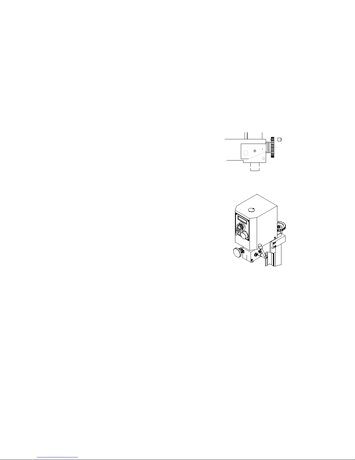
5-2 Travel Adjustment
Using the lifting handwheel can control the traveling of spindle box.
(1) Loosen the screw inside of the spindle box.
(2) Rotate the lifting handwheel, the spindle
box can up or down.
(3) Turn the long handle the spindle can
up or down.
5-3Adjust dip angle of fuselage
Use fine feeding, push the Clutch lever in,
Then rolling the fine feeding handwheel.
Or pull the Clutch out for normal feeding.
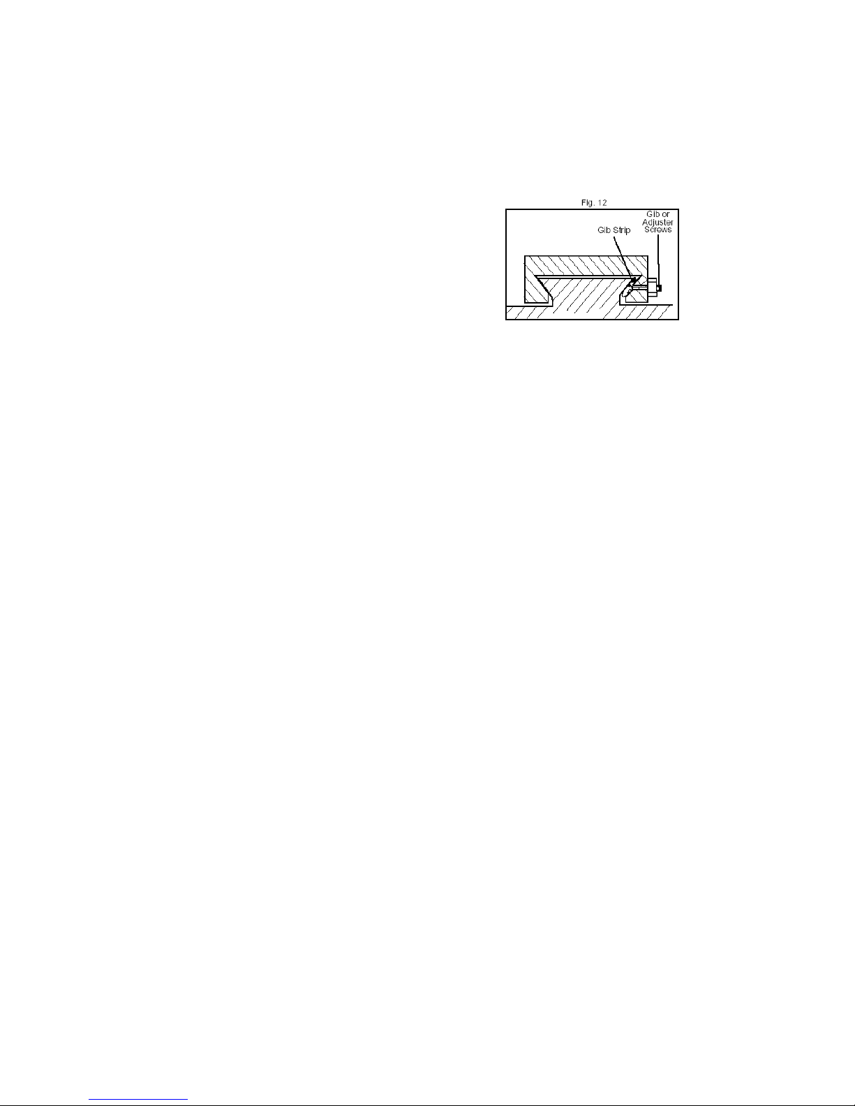
5-4 Miter Wedge Adjustment
After a long term contact motion to the machine function error due to relative
surface motion. Miter wedge act as an interface on each slide face. In order to
eliminate this error, this machine make use of adjust screw making pressure
between two machine parts( ex. Spindle box and fuselage) Adjust and keep up
the contact pressure for maintain its mechanical precision.
16
In order to ensure the precision, the pressure between the two elements needs
to be adjusted appropriately because of abrasion which the machine produced
from the contact motion for same time( about one year).
The following items need to make adjustment
1.Basement and saddle seat slide face.
2.Saddle seat and working table slide face.
3.Fuselage seat and connecting strut slide face.
4.Fuselage and spindle box slide face.
The way to adjust
1.Loosen the locked nuts.
2.Adjust the foremost pressure of the miter wedge by locked nut. If necessary,
please loosen all adjusting screw has to the same.
3.Tighten and loosen the adjusting screws and keep in mind that the pressure
of each adjusting screw has to be the same.
4.Tighten the locked nut uniformly.
5.When locked nut, please use the #3 interior hexagonal wrench to fix the
adjusting screw from rotating to cause the unbalance pressure.
6.Please adjust the middle portion first and then go to toward the interior from
two sides uniformly while you are adjusting the screw in order to ensure an
uniform pressure.
CHAPTER 6 OPERATION AND NOTICE FOR USE
6-1 Method of Operation
□Drilling or Deep Milling
1. According to Chp5, replacement of chuck and tool. Install appropriate
adjustment and tighten it certainly.
2. Select appropriate speed level .( ATTENTION: When spindle is
running, don’t change the HIGH/LOW speed ! )
3. Use press cake or fixture set the workpiece on the working table.
4. Adjust working table (Longitudinal Axis(Y)) and Saddle seat (Cross Axis
(X)) in position.
5.Put Adjusting tools in order and remove all obstacles which are around
the machine.
6.Turn on the main power. Adjust appropriate spindle speed and drilling or
deep milling.
7. Finish working , turn off power and take the spindle to upper position.
8. Clean the machine.
□Face Milling

17
1. According to Chp5, replacement of chuck and tool. Install appropriate
adjustment and tighten it certainly.
2.Select appropriate speed level. ( ATTENTION: When spindle is running,
don’t change the HIGH/LOW speed ! )
3. Use press cake or fixture set the workpiece on the working table.
4.Adjust working table (Longitudinal Axis (Y)) and Saddle seat (Cross Axis
(X)) in position.
5. Arrange all tools in proper place.
6. Turn hand wheel of working table (Y-axis) and saddle seat(X-axis ) to do
face milling.
7. Finishing all steps, turn off power and make spindle return to upper
position, release workpiece. Clean the machine.
6-2 Operation Attention
Please attend the following items as you operate in order to ensure
the operation safety and maintain the capacity of machine.
□Inspection before Turn On
1. Before turn on power, you must check the tool chuck and cutter tighten it
certainly.
2. Inspect whether each machine part has loosen .
3. Check the rod of speed adjustment at correct position certainly.
4. Workpiece is fixed with press cake or fixture certainly.
5. Clean and remove the obstacles around the machine.
□During Operation
1. Drinking alcohol or being worse spirited is absolutely forbidden to
operate the machine.
2. Wearing gloves or necktie is absolutely forbidden to operate the
machine.
3. Select and install appropriate cutter, no loosen.
4. The machine will shaking as follows condition:
a. The depth of cut is too deep.
b. The feeding speed is too fast.
c. The rotation speed is too fast.
d. The machine and stock plane is not fixed firmly.
e. The vice and workpiece is not fixed firmly.
□Protection and Maintenance
1. Please perform the maintenance on each level and make a record.
2. Please turn off the power perform maintenance or projection.

18
3. Please inform our dealer to assign professional person to deal with the
action beyond extent of individual maintenance and protection.
CHAPTER 7 GENERAL SAFETY INSTRUCTION
Warning! When using electric tools, basic safety precautions should always be
followed to reduce the risk of fire, electric shock and personal injury, including
the following. Read all these instructions before operating this product and
save these instructions.
1.Keep work area clean.
-Cluttered areas and benches invite injuries.
2.Consider work area environment.
-Do not expose power to rain. Do not use power tools in damp or wet
locations.
Keep work area well lit. Do not use power tools where there is risk to cause
fire or explosion.
3. Guard against electric shock.
-Avoid body contact with earthed or grounded surfaces (e.g. pipes,
radiators, ranges, refrigerators).
4. Keep children away.
-Do not let visitors touch the tool or extension code. All visitor should be kept
away from work area.
5. Store idle tools.
- When not in use, tools should be stored in a dry, high or locked up place,
out of reach of children.
6. Do not force the tools.
- It will do the job better and safer at the rate for which it was intended.
7. Use the right tool.
- Do not force small tools or attachments to do the job of a heavy duty tool.
Do not use tools for purposes not intended; for example, do not use circular
saws to cut three limbs or logs.
8. Dress properly.
-Do not wear loose clothing or jewelry, they can be caught in moving parts.
Rubber gloves and non-skid footwear are recommended when working
outdoors. Wear protecting hair covering to contain long hair.
9. Use safety glasses.
-Also use face or dust mask if the cutting operation is dusty.
10. Connect dust extraction equipment.
- If devices are provided for the connection of extraction and collection
facilities, ensure these are connected and properly used.
11. Do not abuse the cord.
-Never carry the tool by cord or yank it to disconnect it from the socket, keep
the cord away from heat, oil and sharp edges.
12. Secure work

19
-Use clamp or a voice to hold the work. It is start than using your hand and it
frees both hands to operate the tool.
13. Do not overreach.
- Keep proper footing and balance at all times.
14. Maintain tools with care.
Keep cutting tool sharp and clean for better and safer performance. Follow
instructions for lubrication and changing accessories. Inspect tool cord
periodically and if damaged have it repaired by an authorized serviced
facility. Inspect extension cords periodicall and replace, if damaged. Keep
handle dry, clean and free from oil and grease.
15. Disconnect tools.
When not in use, before servicing and when changing accessories such as
blade, bits and cutters.
16. Remove adjusting keys and wrenches.
Form the habit of checking to see that keys and adjusting wrenches are
removed from the tool before turning it on.
17. Avoid unintentional starting.
Do not carry a plugged-in tool with a finger on the switch. Ensure switch is
off when plugging in.
18. Use outdoor extension leads.
- When tool is used outdoors, use only extension cords intended for outdoor
use.
19. Stay alert.
Watch what you are doing. Use common sense. Do not operate tool when
you are tired.
20. Check damaged parts.
Before further use of the tool, a guard or other part that is damaged should
be carefully checked to determine that it will operate properly and perform
its intended function. Check for alignment of moving parts, free running of
moving parts, breakage of parts, mounting and any other conditions that
may affect its operation. A guard or other part that is damaged should be
properly repaired or replaced by an authorized service center.unless
otherwise indicated in this instruction manual. Have defective switches
replaced by an authorized service facility.
Do not use the tool if the switch does not turn it on an off.
21. Warning.
Using any accessory or attachment other than those recommended in this
instruction manual, may present a risk of personal injury.
22. Have your tool repaired by a qualified person.
-This electric tool is in accordance with the relevant safety requirements.
Repairs should only be carried out by qualified persons using original
spare parts, otherwise this may result in considerable danger to the user.
Table of contents
Other Sieg Power Tools manuals


