Sielaff SU 1500 EC02 Series User manual
GB
With Technical Manual
Original Operating Instructions
SÜ
FS
Softdrop
SÜ 1500............ EC02
SÜ 2020............ EC02
SÜ 2020............RO02
SÜ 2020............ EO02
SÜ 2020............ SO02
SÜ 2020............ SE02
SÜ 2020.............EL02
SÜ 2020............ LO02
FS 1500............ EC02
FS 2020............ EC02
FS 2020............ EO02
FS 2020............RO02
316 00 540 02 _ 251
GB
04.09.20

OPERATING INSTRUCTIONS
2
SÜ/ FS
316 00 540 02 _ 251
1 General..................................................................................................................4
1.1 Technicaldata/Machineidenticationplate..............................................................6
1.2 Safetyinformation......................................................................................................7
1.3 Explanationofsignsandsymbols..............................................................................9
2 Machine diagram................................................................................................10
2.1 Versions ...................................................................................................................10
2.2 SÜ2020model .........................................................................................................11
2.3 FS2020model.........................................................................................................13
2.4 SÜ2020EL02(Softdrop).........................................................................................14
2.5 MachineswithR290chillerunit ...............................................................................15
3 Transport.............................................................................................................16
4 Installing the machine .......................................................................................17
4.1 Requirementsonsite...............................................................................................17
4.2 Installationandcommissioning................................................................................18
4.3 Electricalconnection................................................................................................19
4.4 Fittingacoinmechanism(optional) .........................................................................20
4.5 Mountingthecoinmechanism .................................................................................20
4.6 Settingtheeccentricdisc.........................................................................................20
4.7 Connectingtheadapterkit.......................................................................................20
4.8 Assigningsoftware...................................................................................................20
4.9 Fillingthecoinmechanism(optional).......................................................................21
4.10 Productspecications..............................................................................................21
4.11 Multiex-pusher........................................................................................................21
5 Daily use .............................................................................................................22
5.1 Notesfortheller.....................................................................................................22
5.2 Openingthemachinedoor.......................................................................................22
5.3 Pullingouttheproductcontainers............................................................................22
5.4 Fillingthespiralproductcontainers .........................................................................22
5.5 Goldenrulesforllingspirals...................................................................................22
5.6 Fillingthechutes(FS-seriesonly)............................................................................23
5.7 Doorcontactswitch(Softdroponly).........................................................................23
5.8 Temperature-controlledversion(fresh-foodversion) ...............................................23
5.9 Foodsafetyproductstorage ....................................................................................23
5.10 Foodlabellingdirective ............................................................................................23
6 Cleaning and maintenance................................................................................24
6.1 Caringfortheexternalsurfaces...............................................................................24
6.2 Cleantheproductcontainers...................................................................................24
6.3 Cleaningthedeliveryunit.........................................................................................24
6.4 Cleaningthedustlter .............................................................................................24
7 Software..............................................................................................................25
7.1 Servicekeypadanddisplay .....................................................................................25
7.2 Structureofmainmenu............................................................................................26
7.3 [CHECK] M0 ............................................................................................................27
7.4 [PROGRAMMINGMODE]M1 .................................................................................27

OPERATING INSTRUCTIONS
3316 00 540 02 _ 251
SÜ/ FS
7.5 [COOLINGPROGR.]M2 .........................................................................................28
7.6 [TEST VEND MODE] M3.........................................................................................29
7.7 [SHOW STATISTICS] M4 ........................................................................................29
7.8 [SHOW FULL STAT] M5 ..........................................................................................29
7.9 [PROG./TIMELOCKS]M6 ......................................................................................30
7.10 [INSTALLING MODE] M7 ........................................................................................31
7.11 [SERVICEMODE]M8 .............................................................................................38
7.12 [TUBEINVENTORY]M9..........................................................................................39
7.12.1 SOFTDROP [M10] ............................................................................................................. 42
8 Maintenance work..............................................................................................44
8.1 Maintenanceschedule.............................................................................................44
8.2 Heightadjustment....................................................................................................46
8.3 Routingtheribboncable..........................................................................................47
8.4 Spirals......................................................................................................................47
8.5 Adjusting:Spiralendposition...................................................................................47
8.6 Changingthespiralconguration ............................................................................48
8.7 FittingaMultiexpusher..........................................................................................48
8.8 Removingchutes(FS-seriesonly)...........................................................................49
8.9 Motorlookup/homeposition...................................................................................49
8.10 Back-upbattery........................................................................................................49
8.11 Chillerunit ................................................................................................................50
8.11.1 Removingthechillerunit..................................................................................................... 50
8.11.2 Cleaningthechillerunit....................................................................................................... 51
8.12 ChillerunitSKA705(R290)only .............................................................................52
8.12.1 Checkthegassensor ......................................................................................................... 52
8.12.2 Cleanthegassensor .......................................................................................................... 52
8.12.3 Initiateselftest .................................................................................................................... 52
8.12.4 Checktheanaloguevoltage................................................................................................ 53
8.12.5 Testthesensor.................................................................................................................... 54
8.12.6 Changethegassensor....................................................................................................... 55
8.13 Overviewoftheslots(M32SÜcontrolboard) .........................................................56
8.14 Softwareupdate.......................................................................................................57
8.14.1 Programmingequipment(RedBox).................................................................................... 57
8.14.2 With PC............................................................................................................................... 57
9 Malfunctions.......................................................................................................58
9.1 Errormessages........................................................................................................58
9.2 Displayswhenoperatingandmalfunctions..............................................................59
9.3 Clearingbottlejams(FS-seriesonly).......................................................................59
10 Machineconguration.......................................................................................60
10.1 Containernumbering ...............................................................................................60
10.2 Allocatingmotors .....................................................................................................60
10.3 Tableofmainallocations.........................................................................................61
11 Decommissioning and disposal .......................................................................62
12 Index....................................................................................................................66
13 EU-/EG Declaration of Conformity....................................................................67

OPERATING INSTRUCTIONS
4
General SÜ/ FS
316 00 540 02 _ 251
1 General
Modications
Thetexts,picturesanddatainthismanualreectthetechnicalstatusofthemachineatthetimeofprinting.
Wereservetherighttomakechangesinordertomakefurtherdevelopments.
Complete document
Thisdocumentconsistsof68pages.Ifallthepagesareinconsecutiveorder,yourdocumentiscomplete.
Availability of instructions
Inordertoensuresafeuse,theoperatinginstructionsmustalwaysbeaccessibletotheoperator.These
shouldbereadilyavailableforreferralatalltimes.
ThisoperatingguidecanalsobeaccessedviatheInternetfromoursecuredownloadcentre:(http://www.
siela.de/download-centre/)
Third party documentation
Paymentsystemssuchascoinmechanism,billvalidatororcashlesspaymentsystemscanbettedtothis
machine.
Wewouldliketopointoutthatspecialaccessoriesmayberequiredandspecialsettingsmayneedchanging
inthemachinesoftwareinordertoensureerror-freeoperationofthepaymentsystembeingused.Please
refertotheadditionalthird-partdocumentationfromtherelevantmanufacturer.
Manufacturer
SielaGmbH&Co.KG
Automatenbau
MünchenerStraße20
91567Herrieden
Germany
Hotline
Enquiriesandordersaredealtwithatthefollowingaddress:
Telephone+49982518-0 Switchboard
+49 9825 18-31 51 02 Service-Hotline
Telefax +49982518-315499 Service
+49982518-315299 Sparepartsordering
info@siela.de;www.siela.de
Variants
Pleasenotethattheseoperatinginstructionscoverdierentmachineversions.Forthisreasonsomeofthe
informationmaynotapplytoyourmachine.
This manual covers the following versions:
Model .... Part no.
SÜ 1500 EC02..321 00 000 22
SÜ 2020 EC02..325 00 000 72
SÜ2020RO02 .325 00 000 76
SÜ 2020 EC02..325 00 000 77
SÜ 2020 SO02 .325 00 000 78
SÜ 2020 SE02..325 00 000 79
SÜ 2020 EL02 ..3250000096(Outdoormachine,Soft-
drop)
SÜ 2020 LO02..3250000097(Outdoormachine,Soft-
drop)
FS 1500 EC02..321 00 000 32
FS 2020 EC02..325 00 000 82
FS 2020 EO02..3250000087(Outdoorma-
chine)
FS2020RO02..3250000088(Outdoorma-
chine)

General OPERATING INSTRUCTIONS
5316 00 540 02 _ 251
SÜ/ FS
Identication
1
2
34
1. Manufacturer
2. Machinetype
3. Electricalsupplyratings
4. IfchillerunitusesR290:Symbolfor
“Warningammablesubstances”
Copyright
©SIELAFFGmbH&Co.KGAutomatenbau
Thisdocumentationisprotectedbycopyright.Nopartsofthismanualmaybeusedorreproducedoramend-
edinanymannerwhatsoeverwithoutwrittenpermissionfromtheCopyrightHolder.Thecompanyreserves
allrights,especiallyfortranslation,re-print,usingchartsandpictures,broadcasting,photo-mechanicorother
reproductionandstorageindata-processingsystems.Thisalsoappliestoextracts.
SIELAFFprovidesnoexplanationsorguaranteeswithrespecttothecontentsofthisoperatingguideand
specicallyrejectsanyresponsibilityforacceptinganyimplieddefectclaims.Furthermore,Sielareservesthe
righttoupdatethispublicationandmakechangestoit,withoutbeingobligedtoinformanypersonofthese
changes.
Features
PackagedandchilledfoodstuscanbedispensedfromtheSÜ1500andSÜ2020vendingmachines..Food
canbechilleddownto4°Cinthefreshfoodversionofthismachine.
Productsthatdonotrequirechillingcanbevended,aslongastheytintothespirals.
ColddrinkscanalsobedispensedfromtheFS1500andFS2020machines.
Atwo-line(LCD)displayprovidesselectionandsysteminformation.
Allmachinefunctionsaremanagedandcheckedviaamicroprocessormodule.Salesanderrordataisstored
onthemachinecontrolboard.
Inservicemodetheselectionkeypadisusedalongwiththeprogrammingkeystoprogrammethemachine
controlboard.
Thevendingmachineispreparedforoperationwithacoinmechanismasstandard.
SIELECTORsoftwareforPC-supportedprogramming,basedonWindows,canbeusedtocongurethema-
chine.Thesoftwaresupportstheduplication,creation,savingandprintingoutofallparameters.
OPERATING INSTRUCTIONS
6
General SÜ/ FS
316 00 540 02 _ 251
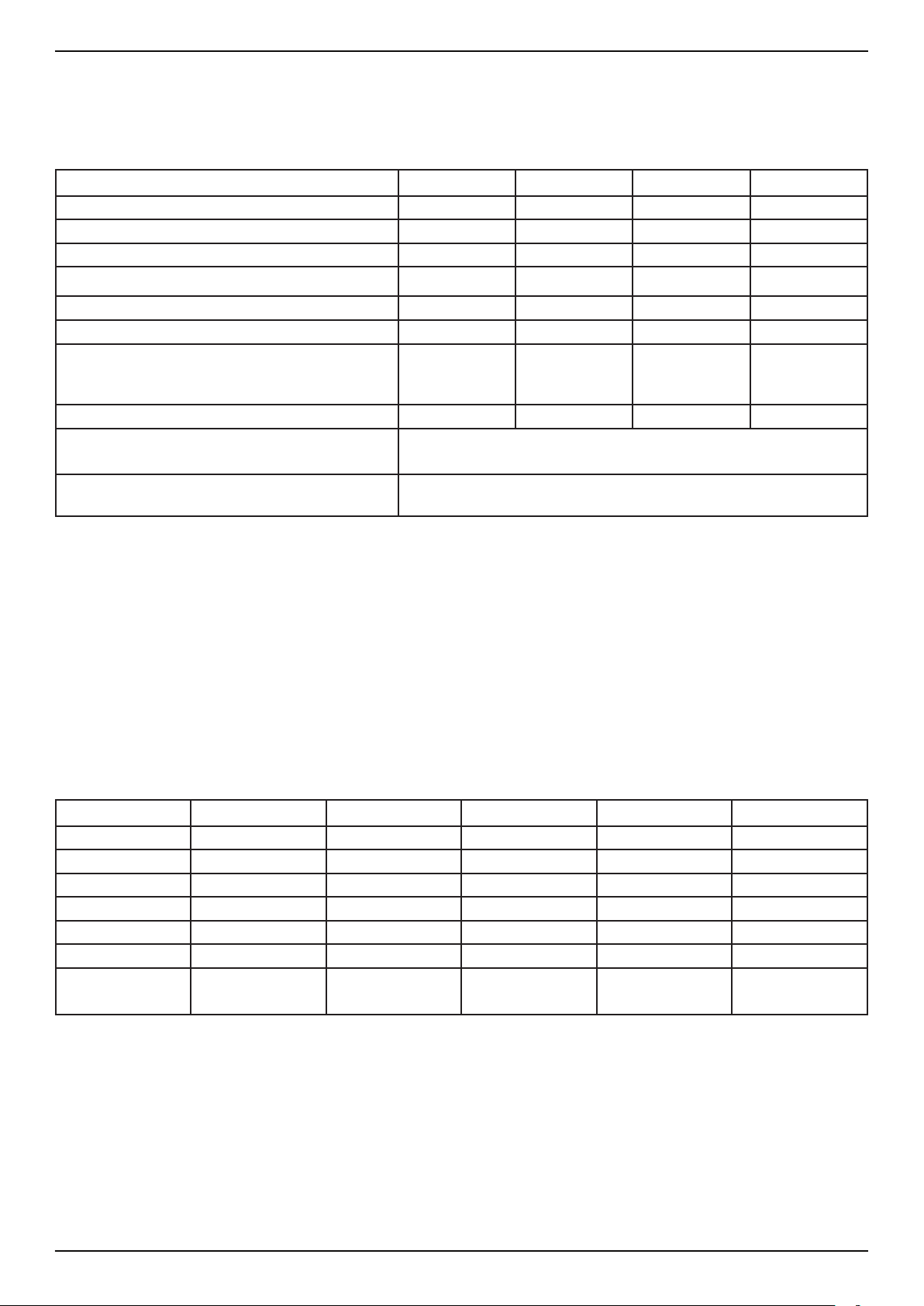
1.1 Technical data/ Machineidenticationplate
Theidenticationplateislocatedinsidethecabinet-topright-andisvisiblewhenthedoorisopen.
Type SÜ 1500 SÜ 2020 FS 1500 FS 2020
Selections max.36 max.60 max.24 max.45
Productcontainers max.36 max.60 max.24 max.45
Height[mm] 1830 1830 1830 1830
Width[mm] 700 990 700 990
Depth[mm] 880 880 880 880
Weight[kg] 295 475 360 475
Electricaldata 220-230V
50/60Hz
min.10A
220-230V
50/60Hz
min.10A
220-230V
50/60Hz
min.10A
220-230V
50/60Hz
min.10A
Powerconsumption[W] max.570 max.670 max.570 max.670
Ambienttemperature(standardchillerunit) +16°Cto+32°C
Ambienttemperature(outdoormachineswith
heater)
-20°Cto+32°C
Weightandpowerconsumptionsarestandardvalues.Theweightmaychangeduetodierentcongurations.
A-ratedsound-pressurelevelemissionintheworkplace LpA< 70 dB
Variationfactor KpA= 6 dB
ThevaluesweredeterminedinaccordancewithEN60335-2-75:2004+A1:2005+A11:2006+A2:2008+A12:2010i.V.withENISO11202:2010.
NOTE:Thesumofnoiseemissionandassociatedvariationfactorrepresentsanupperlimitofvalueswhichmightoccurwhenmeasurementsaretaken.
Information regarding regulation (EU) no. 517/2014
Chiller unit Power Cooling agent Filling quantity GWP CO2-equivalent
SKA 280 1200 W R134a 170g 1430 0.243 t
SKA 290 1210 W R134a 170g 1430 0.243 t
SKA 410 1400 W R134a 245g 1430 0.350 t
SKA 700 1500 W R134a 380g 1430 0.543 t
SKA 701T 1640 W R134a 350g 1430 0.500 t
SKA 851 1770 W R134a 350g 1430 0.500 t
SKA 705 E 2650 W R290 150g 30.00045 t
1)containsHFKW-134ainhermeticallysealedequipment.
2)containspropanegas,C3H8inhermeticallysealedequipment.

General OPERATING INSTRUCTIONS
7316 00 540 02 _ 251
SÜ/ FS
1.2 Safety information
General
• Beforecommissioningtheunit,theoperatinginstructionsshouldbereadandunderstood.
• Theoperatinginstructionsshouldbereadilyavailableforreferralatalltimes.
• Whentransporting,settingup,servicingandrepairingthevendingmachine,strictadher-
encetothefollowingrulesandguidelines-intheirlatestversion-isessential:Standards
setbytheappropriateelectricitycompany,UVV-accidentpreventionregulations,trade
associationguidelines,industrialcode,EC-guidelines,VDEregulations,observanceof
thecurrenthygieneregulations,country-specicregulations,IndustrialSafetyRegulation
-BetrSichV,Workplaceregulations-ArbstättV.
Transportation, installation and commissioning
• Duetoitshighcentreofgravity,thereisariskofthemachinetippingover.Thereforecau-
tionmustbeexercised.Donotjerkthemachinewhenlowering.
• Themachinemustbepositionedonahorizontal,stablebase.Ithastobesecuredtothe
walloroor.
• Themachineisonlysuitableforindooruseindryandheatedareas.
• Machineinstallationandrepairsshouldonlybecarriedoutbytrainedserviceengineers.
• Theventingclearancebetweenthebackofthevendingmachineandthewallonsitemust
beobserved.
• DonotlocatemachineswithR290chillerunitdirectlyalongsideanindentationintheoor
(basemententrance,drain,hollow,recessetc.)
Operating
• Thismachinecanbeusedbychildrenfrom8yearsandolderandbypeoplewithlimited
physical,sensoryormentalabilitiesorlackofexperienceand/orknowledge,providedthey
arelookedafterbyanotherpersonresponsiblefortheirsafetyoriftheyhavereceived
instructionshowtousethemachineandareabletocomprehendthedangersresulting
thereof.Cleaningandmaintenanceworkshouldnotbecarriedoutbychildrenwithout
supervision.
• Childrenshouldbesupervisedtoensurethattheydonotplaywiththemachine.The
vendingmachineisnotsuitableforusebychildrenunder3yearsold.
• Themainsplugmustbeeasilyaccessible.Applianceplugsshouldneverbetouchedwith
wethandsorinsertedintosocketswhendamp.
• Pulloutonlyoneshelfatatime,orthecentreofgravitymaybeshifted.
• Inadditiontothestandardcleaningproceduresmaintenanceworkshouldalsobecarried
outonthemachine.

OPERATING INSTRUCTIONS
8
General SÜ/ FS
316 00 540 02 _ 251
Cleaning
• Themachinedispensesfoodproducts.Themachinemustbecleanedatregularintervals
inordertoavoidhealthriskstoconsumers.
• Onlyuseauthorizedfood-safe,cleaningagents.
• Beforecarryingoutanycleaningremovethemainsplugandforapermanentconnection
switchoanysafetydevices.
• Donotcleanthemachinewithawaterhoseorahigh-pressurecleaner.
Repairs
• TheinsideofthemachinemayhavesharpedgesandcornersAlwayswearprotective
gloveswhencarryingoutmaintenancework
• Damagedpowercablesmustonlybereplacedbythemanufacturer,authorisedservice
centreorequallyqualiedpersoninordertopreventseriousaccidents.
• Useonlygenuinereplacementparts.
• OnlyproductsapprovedbySIELAFFmaybeused.
• Themachinemustnotbeconvertedormodiedinanyway.SIELAFFdisclaimsliabilityfor
anydefectsinsuchcases.
Chiller unit with R-290 refrigerant (propane)
• AfterinsertingthemainsplugorswitchingontheF1-circuitbreakertheswitch-odevice
requiresapprox2minutesforthesafetyshutdowntobeoperational.Duringthistimethe
machinedoesnothaveanyotherfunctions.
Shouldthemachinehowevernotstart,theswitch-odevicemayhaveturnedthemachine
oonaccountofafaultychillerunit.
Inthiscaseanyopenamesandburning/glowingobjectswithina5mradiusaroundthe
machinemustberemovedbeforethemachinedoorcanbeopened.
• Thegassensorinstalledinthechilledareamustnotbetamperedwithasthiscanendan-
gerpersonsandthesurroundingarea.
• Oncethesafetyshutdownhasbeenactivatedthemachineshouldonlybeputbackinto
operationbyaqualiedperson.
• Donotdamagetherefrigerantcircuit.
Intended use
• Themachinemustonlybeusedforvendingpre-packagedfoodorsimilaritems.
• BottledorcannedbeveragescanalsobevendedfromtheFS-range.
• Inammableorexplosivegoodsmustnotbevended.

General OPERATING INSTRUCTIONS
9316 00 540 02 _ 251
SÜ/ FS
1.3 Explanation of signs and symbols
Thisvendingmachinewasmanufacturedinaccordancewithstate-of-the-arttechnologystandards.Nevertheless,
eventhemostexpertlydesignedmachine,cannotbewithoutrisks.
Inordertoensurethehighestpossiblelevelofoperatorsafety,additionalsafetyguidelinesarehighlightedbyusing
thefollowingsymbolswithaccompanyingdetaileddenitions.
Adequatesafetyduringoperationisensuredonlywhenthesesafetyprecautionsareobserved.
Texthighlightedasbelowsymbolisesthefollowing:
Danger
Immediatedangerwhichcouldresultindeathorsevereinjury.
WARNING!
Possibledangeroussituationwhichcouldresultindeathorsevereinjury.
CAUTION!
Dangeroussituationwhichcouldresultininjuryordamagetothevendingmachine.
NOTE
Informationtoavoidcausingdamagetothemachine
TIP
Informationtofacilitatehandlinganduseofthevendingmachine.
Thefollowingdangersymbolsmayalsobeusedincertaininstances:
WARNING electrical energy! Risk to life!
Thissymbolwarnsthatelectricallylivecomponentsareinstalledinthisarea.Coversmarkedwith
thesesymbolsshouldonlyberemovedbyauthorisedelectricians.
Observe the handling instructions for contact with electro-statically-sensitive components
and assemblies (ESD)
Behindcoversmarkedwiththissymbolarepartsandcomponentsthataresusceptibletoelectri-
caldischarge.
Itisimperativethatplugconnections,electricalleadsandcomponentpinsarenottouched.
OnlyspecialistpersonnelwithESDknowledgeareauthorisedtoworkonthemachine!
ATTENTION! Risk of injury
Theremaybesharpedgesinsidethemachine.
Wearprotectivegloveswhencleaningthemachine.
Attention! Danger of crushing!
Riskofhandinjuries!
DANGER! Flammable materials!
Thissymbolwarnsaboutammablematerials.Maycauseseriousinjuryordeath.Sourcesof
ignitionsuchasburningcigarettesorlightersmustbedistancedbeforeopeningthemachine
door.

OPERATING INSTRUCTIONS
10
Machinediagram SÜ/ FS
316 00 540 02 _ 251
2 Machine diagram
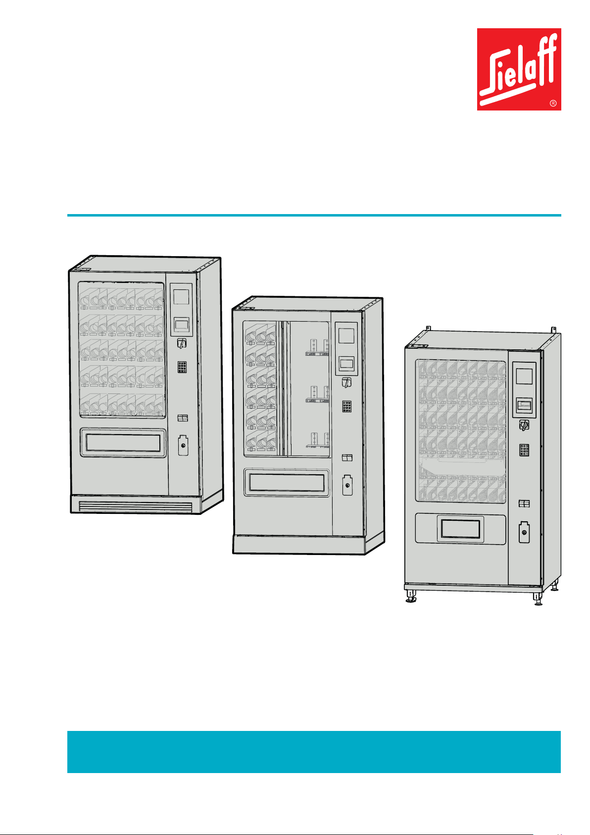
2.1 Versions
FS 1500
SÜ 1500
SÜ 2020 FS 2020
SÜ-Series(confectionery) FS-Series(bottles+confectionery)

Machinediagram OPERATING INSTRUCTIONS
11316 00 540 02 _ 251
SÜ/ FS
2.2 SÜ2020 model
Mountingbracket
POS
Display
Coininsert
Selectionkeypad
Coinreturnbox
Lockinglever
Kickplate(optional)
Airinletgrid(SÜ20202Tonly)
Internaldoorforcashbox
Servicekeypad
Coinmechanism(optional)
Removablecashbox
refundbutton
OPERATING INSTRUCTIONS
12
Machinediagram SÜ/ FS
316 00 540 02 _ 251
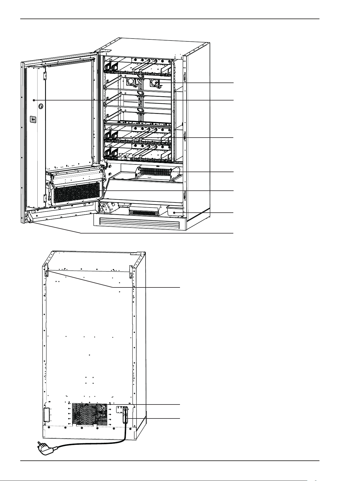
DierencesbetweenSÜ2020andSÜ20202T:Themachine
with2temperaturezoneshasafanonthebackwall
Fan(SÜ20202Tonly)
Spiralcontainer
Evaporator
Productdeliveryunit
Condensedwaterdriptray
Switch(SÜ20202Tonly)
Interiordoor,cover
Mountingbracket
Mainsconnectioncablewithplug
Warmairventilationgrid

Machinediagram OPERATING INSTRUCTIONS
13316 00 540 02 _ 251
SÜ/ FS
2.3 FS 2020 model
Note
Spiralcompartmentsandbottle/canchutescanbe
combinedindividually.
Productcontainer
Spiralcompartment
Chillingmodule
Condensation/evaporationbowl
Kickplate
Displaywindow
Samplebottle
Rearwalldisplaywindow
Illumination

OPERATING INSTRUCTIONS
14
Machinediagram SÜ/ FS
316 00 540 02 _ 251
2.4 SÜ 2020 EL02 (Softdrop)
1 Wallspacingbrackets
2 POS-window
3 Display
4 Coininsert
5 Selectionkeypad
6 Coinreturnbox
7 Lockinglever
8 Kickplate
9 Airinletgrid(SÜ20202Tonly)
10 Deliveryunitap
11 Glasspanel
1 Productdeliveryunit(lightbarrieroptional)
2 Reinforcementforprotectivecover
3 Protectivecover
4 Inspectionwindow
5 Shaftcoupling

Machinediagram OPERATING INSTRUCTIONS
15316 00 540 02 _ 251
SÜ/ FS
Senderboard Receiverboard
Signal
Viewofproductdeliveryunitfromabove(withoptionallightbarrier)
2.5 Machines with R290 chiller unit
ForsafetyreasonsmachineswithchillerscontainingR-290refrigerant(propanegas,C3H8)
arettedwithagassensorinconjunctionwithaswitch-odevice.
Powersupplyboard
Gassensor
9-poleplug(reversepolarityprotected)
Serviceboard
Identicationplatewithsymbol“Warning
ammablesubstances”
Yellow - green - red
Red illuminates for 1 second
Self-testinitiated
Red is on permanently
Self-testfailed
Green is on permanently.
Self-testsuccessful
Yellow is on permanently
Mainsvoltageforthemachinehasbeenenabled.

OPERATING INSTRUCTIONS
16
Transport SÜ/ FS
316 00 540 02 _ 251
3 Transport
Observe the following instructions
▪Movethemachineonlywithapallettruckoraforklift.Placetheforksonthewidesideofthemachine.Removethe
kickplatesrst.
▪Donottransportthemachineintheair.
▪Alwaysmovethemachinewithcare.
▪Preventitfromslidingsideways.
▪Donotmovethemachineoninclinedramps,usestair-walkers.
▪Observethemachine'scentreofgravity.Duetoitsdesignthecentreofgravitycanbehigh.Riskoftippingover.
Storage
▪Thevendingmachineshouldbestoredinacleananddrylocation.Useasuitablecovertoprotectitfromdirt,humidity
anddamage.
▪Removetheproductsandleavethemachinedoorslightlyajartoallowthehumiditytoescape.
Temporary shutdown
Themachinemaybeshutdowntemporarily.
Howtoproceed
▪Removethemainsplug
▪Removetheproducts
▪Cleantheproductcontainers
▪Leavethemachinedoorajar
▪Tore-commissionrefertotherelevantsection
Centreofgravity
Installingthemachine OPERATING INSTRUCTIONS
17316 00 540 02 _ 251
SÜ/ FS
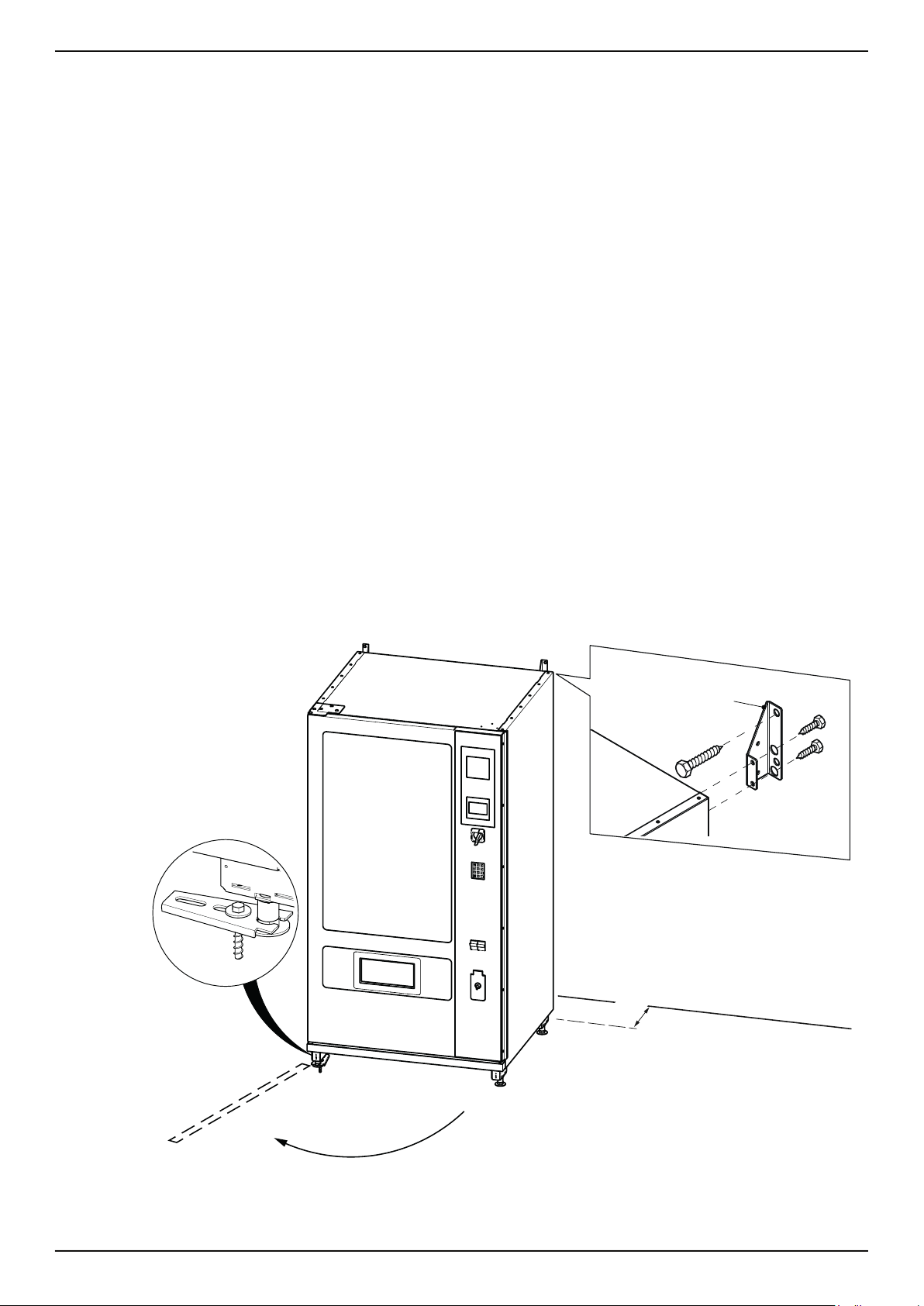
4 Installing the machine
4.1 Requirements on site
▪Themachinesaredesignedforindooruseonly.Theymustnotbeinstalledoutdoors.Exceptforspecial
outdoormod-
els
.
▪Theoormusthaveanadequateloadbearingcapacity.Notetheweight(refertotechnicaldata).
▪Themachinemustnotbeinstalledinaircontainingsaltorchlorine,suchasinanindoorswimmingpool.
▪Checkthattheambienttemperatureisinaccordancewiththeclimateclassofthechillerunit!
▪Donotinstallthemachineinplaceswherewaterhosesorahigh-pressurecleanerisused.
▪Themachine'sglassfrontmustnotbeexposedtodirectsunlight.Thechillerunitisnotdesignedforthis.
▪Inadverseweatherconditions(highhumidity,highoutdoortemperature)thefrontpanelsonthemachinemaymistup.
Thisisatemporaryoccurrenceandnotgroundsforcomplaint.
▪Themachinemustbeinalevelposition.
▪Themachineisdeliveredreadyforconnection,withcableandshock-proofplugforasingle-phaseACsupplyof230
V/50Hz.Ithastobepluggedintoaproperlyinstalledsocketwithearthconnection.Theplugmustbeeasilyaccessible
afterinstallation.Donotuseextensioncablesandmultiplesockets.
▪Apermanentinstallationshouldonlybecarriedoutbyaqualiedelectrician.
2x
50 mm
optional:
Floorxingkit
Part-No.6030263900
Wallspacerbracketskit
Part-No.6050103500
Standardmachine:120°
Outdoormachine:140°
OPERATING INSTRUCTIONS
18
Transport SÜ/ FS
316 00 540 02 _ 251
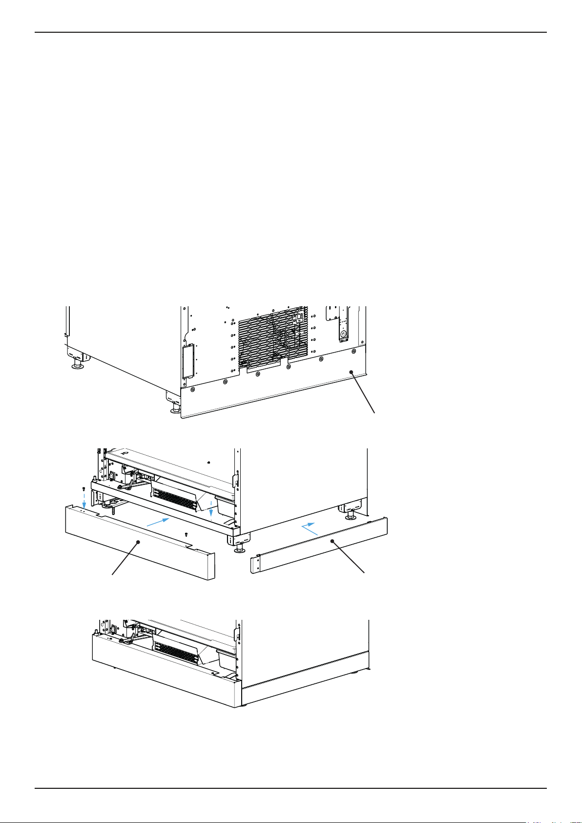
Kickplate
(optional)
Kickplate
(aerationslotsoptional)
4.2 Installation and commissioning
1. Unpack, position. level and secure the machine
2. Open the machine door; the key can be found at the back of the machine by the power cable
3. Remove transportation locks (if tted)
4. Establish electrical connection
5. Fit suction protection / kickplates (optional)
6. Fit coin mechanism (optional) etc.
7. Switch the machine on at main switch.
→ Themachineisoperationalwhen[READYTOUSE]isshowninthedisplay.
• Inordertoavoidthemachinetakinginthehotair,whichhasalreadybeendischarged,suctionprotectionmustbe
attachedtotherearofthemachine.Itmustbettedsothatitisushwiththeoor.
• Suctionprotectionisnotrequiredifthemachineisttedwitharearadvertisingpanel.
Suctionprotection
Transport OPERATING INSTRUCTIONS
19316 00 540 02 _ 251
SÜ/ FS
4x
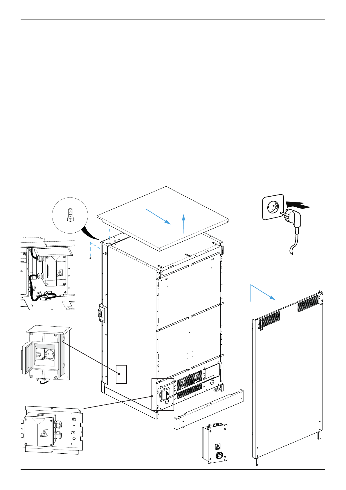
4.3 Electrical connection
Standard machine
• Themachineisdeliveredreadyforconnection,withcableandshock-proofplugforasingle-phaseACsupplyof
230V/50Hz.Itmustbepluggedintoaproperlyinstalledsocketwithearthconnection.
• Donotuseextensioncablesandmultiplesockets.
Outdoor machine
• Thexedconnection(hard-wired)shouldonlybeinstalledbyanelectrician
• Removetherainshield;removethe4hexagonalscrews,slidetheroof
backwardsanddetach.Removethebackpanel.
Takecarewhenmakingtheelectricalconnectiontothedistributorbox
Re-attachrainshieldandbackpanelinreverseorder.
• Theconnectioncablehastobeinstalledinawaythatitcannotbedamagedfromtheoutside.
• Includeadisconnectingdevicewithatleast3mmcontactopeningall-pole;fuseprotectionwithmax.16AF1
circuitbreakerwithmax30mAresidualcurrent
• JunctionboxwithF1andshockproofsocket:Themachine'spowercableispluggedintotheshockproofsocket.
Thisgivesthemachineitsownfuseprotection(F1-switch).
optional:
optional:
optional:JunctionboxwithF1
andshockproofsocket

OPERATING INSTRUCTIONS
20
Transport SÜ/ FS
316 00 540 02 _ 251
Coinmechanism
(optional)
Coinrefundmotor
Releaselever
Refundlever
MDB
connection
Motorizedcoinreturn
Holdingplate
4.4 Fitting a coin mechanism (optional)
Machinesaregenerallysetandtestedtoaspecicprotocolfortherelevantcoinmechanism.Fittingthecoinmecha-
nismisusuallycarriedoutbythecustomer.
4.5 Mounting the coin mechanism
Followtheinstructionsprovidedbythecoinmechanismmanufacturer.
Hangthecoinmechanisminthespaceprovided.Usealockingscrewwherepossible.
4.6 Setting the eccentric disc
Adjustthemotorisedcoinreturnsothatthereturnleveronthecoinmechanismisrmlyactivatedwhenpressing“R”
therefundbutton.Positionthecoininsertchutesothatthecoinscaneasilyfallintotheentryfunnelonthecoinmech-
anism.
4.7 Connecting the adapter kit
Thecoinmechanismandthemachinecontrolboard(VMC)mustbeconnectedelectrically.
KitforExecutive:................ 306 02 562 00
KitforBDV:........................ 310 01 530 00
Otheradapterkitsareavailableuponrequest.
Pluginmaleandfemaleconnectorssecurely.
4.8 Assigning software
1. Access the menu [INSTALLING MODE] M7: [ M ] + [ 7 ] + [ E ]
2. Access [CREDIT SYSTEM] by pressing [ M ] x 1. Press [ E ] to enter.
3. Press [1] to set the communications protocol e.g. [Executive].
4. Press [ E ] to enter.
5. Return to the main menu by pressing [ M ] + [ L ].
This manual suits for next models
27
Table of contents
Popular Vending Machine manuals by other brands

Seaga
Seaga SM16S Service and parts manual

SandenVendo
SandenVendo SVE C36-XS User and maintenance manual

Necta Vending Solutions SpA
Necta Vending Solutions SpA Zeta CB Series Installation - use - maintenance

Thames & Kosmos
Thames & Kosmos 550104 Experiment manual

Crane
Crane Linea user manual

Seaga
Seaga Intelligent Inventory Control IQ640 Service and parts manual


