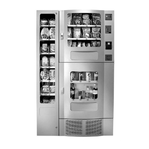
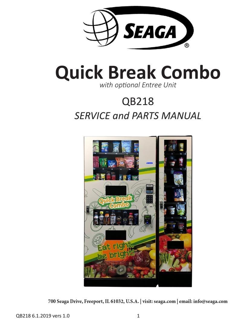
Seaga SM16S Building instructions

Rev.1 – 01.2016.EL950.1.9 1
SERVICE and PARTS MANUAL

Rev.1 – 01.2016.EL950.1.9 2
INTRODUCTION
Congratulations on the purchase of your vending machine. This vending machine has been designed to give youmany
years of dependable service. It requires little maintenance and is easy to set up and operate.
READ THIS MANUAL COMPLETELY
Your vending machine is designed to operate simply and reliably, but to take full advantage of your vendor,
please read this owner’s manual thoroughly. It contains important information regarding installation and
operations, as well as a brief trouble-shooting guide.
EQUIPMENT INSPECTION
After you have received your vendor and have it out of the box, place it on a secure surface for further
inspection. Note: Any damages that may have occurred during shipping must be reported to the delivery
carrier immediately. Reporting damages and the seeking of restitution is the responsibility of the equipment
owner. The factory is willing to assist you in this process in any way possible. Feel free to contact our
Customer Care Department with questions you may have on this process.
It is important that you keep the original packaging for your vending machine at least through the warranty
period. If your machine needs to be returned for repair, you may have to purchase this packaging if it is not
retained.
Once you have your vendor located, we suggest that you keep this manual for future reference, or you can
view this manual online at www.seaga.com. Should any problems occur, refer to the section entitled
“TROUBLESHOOTING”. It is designed to help you quickly identify a problem and correct it.
seaga.com
Seaga Manufacturing, Inc.
700 Seaga Drive
Freeport, IL 61032 U.S.A.
For Service and Customer Care in the US:
8:30 a.m. - 4:00 p.m. CST. Monthru Fri
815.297.9500 ext 160
815.297.1758 Fax
email: customercare@seaga.com
Seaga UK Ltd.
5 Leodis Court, David Street
Leeds, LS11 5JJ UK
+44(0)3300 885673
email: service@seaga.co.uk
Seaga India Pvt Ltd.
Plot No.2, Sector 4-B
Industrial Estate, HSIIDC
Bahadurgarh 124507 Haryana, India
+91 (0) 12 7664 5693
+91 (0) 12 7626 7079 Fax
email: service@seagaindia.com

Rev.1 – 01.2016.EL950.1.9 3
SPECIFICATIONS
The vending machine is comprised of two (2) units - Snack Unit (SM16S) and Beverage Unit (SM6RD).
Installation and setup of these units is explained in the next sections of this manual.
Machine Description Snack Unit Beverage Unit
Model Number SM16S SM6RD
Height (in) 28.5” (72 cm) 41” (104 cm)
Width (in) 30.2” (77 cm) 30.2” (77 cm)
Depth (in) 28.5” (72 cm) 28.5” (72 cm)
Volts (V) 115 (230) 115 (230)
Frequency (Hz) 60 (50) 60 (50)
Watts (W) 60 (220) 360 (1150)
Current (A)* 0.5 3.0
* - Current draw varies depending on Operating Conditions and Load and are subject to change.
The vending machine is designed for use in indoor conditions only. The
recommended operating environment is 75° F and 40% RH.

Rev.1 – 01.2016.EL950.1.9 4
OVERVIEW
Thismanual covers Installation, Setup, Programming and Service instructions. It is extremely important that
this manual be read thoroughly prior to commissioning the vending machine in the field. This will ensure a
satisfactory long-term performance.
The vending machine consists of two (2) separate cabinets that are installed together via mechanical means
and connected via electrical connections to operate as ONE unit.
The Snack Vendor (SM16S) consists of two (2) trays. The first and second trays have 4 selections each
(Tray 1 – 111, 113, 115, 117, Tray 2 – 121, 123, 125, 127). The third tray has 8 selections (131 through
138). The top two trays are normally used for products that are wider such as chips, pastries etc. and the
third tray is used for Confectionary items such as candy bars. The Snack Vendor (SM16S) also houses all
the paymentmechanisms and electronic VendingMachine Controller (VMC) on the right side of the cabinet,
as shown in Figure 19. The payment mechanisms, electronic components (such as VMC) and transformer
are installed on a vertical shelf that slides out for easy access. The connectors to connect the Beverage
Unit (SM6RD) are also provided in this vertical shelf of the Snack Vendor (SM16S).
The Beverage Vendor (SM6RD) is designed with a vertical dropsystem. The Beverage Vendor also houses
the removable Refrigeration System. The cabinet of the Beverage Vendor has a delivery system that has
6 selections for Cans or Bottles (140 through 146). The loading instructions are given in subsequent
sections. The refrigeration system is installed at the bottom of the Beverage Vendor and there is a foamed
separation between the cabinet interior and the refrigeration system. The installation, setup and functionality
of the refrigeration system is explained in the section titled Refrigeration.
RECEIVING, INSPECTION, UNPACKING AND TESTING
After you have received your vending machine, inspect all three individual vendor components. Note: Any
damages that may have occurred during shipping must be reported to the delivery carrier immediately.
Reporting damages and the seeking of restitution is the responsibility of the equipment owner. The factory
is willing to assist you in this process in any way possible. Feel free to contact Seaga Customer Care with
questions you may have on this process. Once you have your vending machine located, we suggest that
you keep this manual for future reference.
The vending machine is placed on a wooden pallet and stretch-wrapped. Please exercise caution while
cutting into the stretch-wrap with a sharp tool such as a utility knife, as it may cause scratch marks on the
machine.
The Snack and Beverage Units are boxed in two (2) separate cardboard boxes. The Snack Unit box is
placed on top of the Beverage Unit. After removing the stretch wrap, remove the Snack Unit and place it
aside. USE EXTREME CAUTION AS THE TOP OF THE BOX IS NOT ATTACHED TO THE BOTTOM OF
THE BOX. The top of both the snack and beverage units slide up for removal. Remove the Beverage Unit
from its box and place it in the desired vending location. Remove the Snack Unit from its box and place it
on top of the Beverage Unit carefully. Please use proper lifting and safety precautions while placing the
Snack Unit on top of Beverage Unit.
Open all Unit doors and remove the packing materials. Keys can be found in the white envelope placed in
the vend area of the Snack Unit. Remove the tape on the tray levers of the Snack unit. Also remove the
protective paper from under each coil as well as ties securing the ends of the coils during shipping. Remove
all protective plastic from the window lenses.
Remember: at least two people are necessary to move any of the components of the vending machine.
Follow proper safety standard for lifting and working with electronic/refrigerated equipment.
Rev.1 – 01.2016.EL950.1.9 5
INSTALLATION
Once the machines have been unpacked and placed in their permanent location, the electrical connection
and mechanical connection must be made. Tools required: Adjustable wrench and Philips screwdriver. For
optimal installation, follow the order of connections as outlined below:
1. Mechanical Connection between Snack and Beverage Units:
The Snack and Beverage units must be screwed together for safety purposes. Two screws are
provided in the white envelope found in the vend area of the Snack unit. Square the fronts and
sides of the Snack and Beverage units. Open the Snack unit door and locate the two holes at the
bottom of the unit. Insert both screws and tighten.
2. Electrical Connection between Snack and Beverage Units and Beverage Display Lighting
Connection:
Remove the Styrofoam insert from the opening in the upper right corner of the beverage unit and
save this for reinsertion. Open the Beverage unit door and locate the beverage main harness and
refrigeration harnesses. See Figure 1. Insert harnesses through the opening up into the Snack
cabinet, see Figure 2.
Figure 1 – Beverage and Refrigeration Harnesses Figure 2 – Inserting Beverage and
Refrigeration Harnesses
Connect the refrigeration harnesses to the two connectors foundin the snack unit that are tied together,
see figure 2 above. (Note: the single harness located inside the snack unit is for the LED lighting which
is the next step).
Beverage and
Refrigeration
Harnesses
Refrigeration
Harnesses
Connected

Rev.1 – 01.2016.EL950.1.9 6
Figure 3– Making Drink Connections
The Beverage Unit has a live product display that is lit by LED lighting. Locate the LED Light
harness on the inside of the Beverage Unit Door. Insert the LED Light harness up through the
Snack Unit as done for the other connections. Connect the LED Light harness to the main board
connection as shown in Figure 4.
Reinsert the Styrofoam piece for maximum insulation of the refrigeration unit.
Figure 4 – Beverage Display LED Light harness connection in Snack Unit
Beverage main harness attaches to
bottom connector port
MENUS Button
Beverage
Display LED
Light
Harness;
insert
through
snack unit.
Connect to
single
harness in
Snack Unit.

Rev.1 – 01.2016.EL950.1.9 7
LOADING PRODUCT TRAYS
Open thefront door of vendor, and lift upthe plastic locklever onthe right side of the tray to unlock. Holding
the lever up, grasp the tray and lift the front of the tray slightly and pull forward. The tray will slide out and
then tilt down to make loading of products easier. Load only one product tray at a time (See Figure 5).
Figure 5 – Slide-out product trays
1. To Load Product in Snack Unit:
a. Pull the desired product tray all the way forward. Product tray will tilt down.
Note: Pull out only one (1) product tray at a time
b. Place product in proper size coil.
Note: Bottom of product must rest on the product tray and not on the
Coil. Load each column from back to front.
Note: Fill all product trays fully; do not leave any spaces behind or between items
c. Once product tray is fully loaded, lift and push it back in.
Repeat steps a through c until all product trays are fully loaded. Special Note: We suggest that you always
partiallyfill the tray with product and perform at least five(5) test vends. Test vends can be performed easily
by entering Service mode and using the test function.
Lift up plastic lock
lever Grasp tray
while
holding up
lever and
pull
forward

Rev.1 – 01.2016.EL950.1.9 8
PRODUCT LOADING
Snack Unit
Wide products such as Chips bags etc. are loaded in Tray 1 and Tray 2. Narrow products such as Candy
bars are loaded in Tray 3. See Figures 6a and 6b.
Figure 6a – Loading Product
Figure 6b – Loading Product
Correct – load
product between
coils, resting on
the product tray,
never on the
bottom loop of
the coil.
Incorrect
Coil
Product Tray
Incorrect Incorrect
Correct – load product between coils,
resting on the product tray.

Rev.1 – 01.2016.EL950.1.9 9
COIL ADJUSTMENT
If you are required by a location to vend a product that does not fit into the standard coil installed, you
may need to order a different coil and install it. To replace a coil:
1. Remove the Coil from the Coil Driver by lifting the back of the coil up off the coil driver. You will
need to move the bottom of the coil clear of the coil driver to completely remove the coil. See
Figure 7.
2. Align the new coil end with the front of the tray, which gives the coil better contact with the
product. The position of the coil in the coil driver is adjustable to assist you in aligning the new coil
at the front of the tray. See Figure 7.
Figure 7 – Removing and Aligning a Coil
If you are experiencing vending issues with certain products, you may need to adjust the coil rotation to
better provide the momentum to push the snack off the tray and into the delivery area. To adjust the coil
rotation:
1.) Squeeze the two tabs on the back of the coil driver and pull the coil driver and coil toward the front
of the tray to remove it.
2.) Turn the coil clock-wise 1/8 of a rotation.
3.) Reinsert the coil driver with coil attached back into the motor, through the back wall of the tray.
4.) Load the tray and perform at least 5 (five) test vends to insure a proper vend.
5.) If the item does not vend consistently, repeat another 1/8 of a rotation until you are confident of
consistent vend function.
Figure 8 – Coil Rotation Adjustment
Coil Driver with
three (3)
adjustment
options
Lift Coil
Apply pressure to
the straight part of
the coil that is
inserted into the
Coil Driver. Lift up
on the Coil to
remove.
Back of Product
Tray, Snack or
Entree
Squeeze two tabs
on the back of the
Coil Driver
Pull the Coil Driver
and Coil forward;
Rotate 1/8 of a
turn and reinsert
back into product
tray.

Rev.1 – 01.2016.EL950.1.9 10
BEVERAGE UNIT
The Vertical Drop Columns in your machine use an Auger that rotates counter-clockwise to drop the drink
into the Product Bin. The columns employ the use of a combination of metal Shims to hold the front-most
product from dropping during the first vend. On the second vend, the Auger rotates counter-clockwise
further and allows the front product to vend. A third rotation occurs only if the column is set for cans. The
combination of Auger, Shim(s) and Rear Spacer position allow for different sizes and types of product
packaging.
To control the rotation of the Auger, there is a Home Switch located behind each vertical drop column
motor. There are Cams installed on the front of each auger, one for bottles and one for cans. The lobes
on these cams determine the stopping point of the Auger for each vend.
Figure 9 below is an illustration of the factory default settings for each column. Be aware that each
column has been set for specific brands of products in the size listed. Note that columns are marked for
“CANS” and “BOTTLES” with labels on the interior beverage door:
Figure 9 – Vertical Drop Columns
Vertical Product Columns – Load products horizontally (laying down)
1.) For most bottles, place top of the first bottle against the front of the column, making sure the Sold Out
Switch is depressed. Place the second bottle to the rear of the column, facing the bottom of the bottle with
the bottom of the first bottle. See Figure 9. Load 12 oz. cans bottom to bottom in the first two positions,
then top to top in the back position. Load 16 oz. cans bottom to top. 20 oz. Gatorade bottles are loaded
bottom to top.
2.) To adjust the rear spacer, grasp firmly and lift, freeing the spacer from the slots in the column sides.
Move the rear spacer to the closest slot to the back of the bottle or can placed in the rear of the column.
Insert the bottom left corner first. The gap between the rear spacer and the rear bottle or can must be less
than ½ inch. The slots are in ½ inch increments to let you adjust for many sizes of products. Lower the
rear spacer into the new position, making sure the spacer is straight vertically.
3.) Finish loading to the top of the column, making sure the items are perfectly horizontal and not tilted or
skewed in the column.

Rev.1 – 01.2016.EL950.1.9 11
Note: There are many variations of packaging among the beverage brands. These instructions are
meant to be a guideline. If you have packaging that isn't mentioned or shown, experimentation will
be necessary for a proper vend.
Product Size Type Max
Capacity Loading Instructions
Home
Switch
Mounting
Ring
Position
Shim
Position
Rear
Spacer
Position
Coca-Cola
and
varieties 16.9 oz/500 ml Bottle 16 Load bottom to bottom 5 Open 20
Nesquik 14 oz/414 ml Bottle 16 Load bottom to bottom 4 Half
Open 9
Pepsi, Diet
Pepsi, Mt.
Dew and
varieties
16.9 oz/500 ml Bottle 16 Load bottom to bottom 5 Open 20
7 up and
Diet 7up 16.9 oz/500 ml Bottle 16 Load bottom to bottom 5 Open 20
Dr. Pepper,
Diet and
varieties 16.9 oz/500 ml Bottle 16 Load bottom to bottom 5 Open 20
Gatorade 12 oz/355 ml Bottle 18 Tops to front of machine 4 Open 14
Water -
Nestle Pure
Life, Ice
Mountain,
Zephyrhills,
Ozarka,
Deerpark,
Deja Blue
16.9 oz/500 ml Bottle
(soft) 16 Load bottom to bottom 5 Open 15
Kick Start,
Monster,
Rock Star,
etc. 16 oz/473 ml Can 18 Load bottom to bottom 5 Open 19
Standard
size 12 oz.
cans 12 oz/355 ml Can 21 Bottom to bottom then
top to top 4 Closed 12
Vitamin
Water 20 oz/591 ml Bottle 18 Tops to front of machine 2 Closed 14
Sobe Bottle 20 oz/591 ml Bottle 18 Tops to front of machine 2 Closed 14
Starbucks
Double
Shot, V8
Vfusion 8.4 oz/248 ml Can 24 Bottom to bottom then
top to top 3 Kit
Required 8
Large
bottles, 24
oz. plus 24 oz/710 ml Bottle Na Do not vend Na Na Na
Gatorade 20 oz/591 ml Bottle 18 Tops to front of machine 2 Closed 14
Aquafina 20 oz/591 ml Bottle 14 Load bottom to bottom 4 Closed 15
Red Bull 8.4 oz/248 ml Can 24 Bottom to bottom then
top to top 3 Kit
Required 8
By adjusting the Shims and/or changing the cams any column can be converted to cans or bottles.
Contact Technical Support if you need assistance.

Rev.1 – 01.2016.EL950.1.9 12
The shim positions are adjustable in each column and are factory set as shown below.
To adjust the shim, loosen the thumb screw ONLY SLIGHTLY and slide the adjustment bar to the correct
position. Tighten the thumb screw. Unusually shaped product may take some testing, trial and error to
determine the correct adjustment.
Specialty kits for Red Bull and other packaging are available for purchase from Seaga’s Parts
Shim position – 16.9 oz bottles and cans
Adjustment Bar
Shim position – 12 oz. cans
Thumb screw Side Wall
Adjustable Shim

Rev.1 – 01.2016.EL950.1.9 13
Home Switch Adjustment
Due to variance in product sizes, it may be necessary to adjust the position of the Home Switch. This can
be accomplished by rotating the Home Switch Mounting Ring clockwise or counter-clockwise in one step
increments to adjust the stop position of the Auger. There are 9 adjustment increments etched into the
Home Switch Mounting Ring as shown in Figure 10:
Figure 10 - Front of one vertical drop selection; motor removed
To make adjustments:
1.) With the column empty, test vend the selection to rotate the Auger until the opening faces the 3:00
o’clock position (Figure 11). This is the beginning of the vend cycle and the Home position of
the auger.
Bottle Cam
Sold Out Switch
Home Switch Mounting Ring
Home Switch
Home Switch Mounting Ring
Adjustment Steps 1 through 9

Rev.1 – 01.2016.EL950.1.9 14
Figure 11 – Auger in Home position with opening facing 3:00
2.) Load a single row of drinks on top of the Auger
3.) Perform a single test vend – if no product drops, the Auger did not turn far enough. Adjust the Home
Switch Mounting Ring counter-clockwise one notch only.
4.) If two products drop on the first vend in Step 3, the Auger turned too far. Adjust the Home Switch
Mounting Ring clockwise one notch only.
5.) Go back to Step 2, noting that one and only one product should drop. If this is a 12 oz. can column,
test three times to insure that all three products drop correctly.
Fill the column to the top and run a full cycle one more time, as the weight of a full column may change
the dynamics of the vend operation. If a full cycle vends one product per vend, the column is set correctly
Figure 12– Can Cam and Bottle Cam (Bottle Cam shown Installed on Auger)
Bottle Cam shown
installed on Auger.
Lobe
Bottle Cam Can Cam
Lobes

Rev.1 – 01.2016.EL950.1.9 15
Figure 13 – Rear Spacer Adjustment
Figure 15 – Removing Vertical Drop Motors and Auger System
Note: Always unplug the vending machine from the wall before replacing any parts.
Figure 14 - Rear Spacer
Rear spacer
position for
16.9 oz and
(20th slot)
You may need to adjust due to product height variance.
Remove two fasteners holding
in motor/bracket. Remove Auger by
pulling straight out…
If replacing motor,
unplug the wire
harness and slide
motor off shaft.
If replacing auger,
continue with the
instruction tothe
right…
Rear spacer
position for 12
oz. cans (12th
slot)
Insure that rear Auger
Bushing does not become
disengaged from back of
column
Insert this first, then
align Rear Spacer
vertically
Slide remaining hooks
into proper slots after
Rear Spacer is straight

Rev.1 – 01.2016.EL950.1.9 16
LIVE DRINK PRODUCT DISPLAY
Your machine has a live product display shelf for the drinks. Take care to use packaging that is in perfect
condition and products that are still within their expiration date to present the best possible advertisement
to your potential customers. To display your products:
1.) Remove the Drink Display Back Panel by loosening and removing the thumb screws located on
either side of the panel.
2.) Place each beverage, in order of selection, in the display window taking care to make them evenly
spaced and oriented properly toward the front of the machine where the customer will see them.
3.) Reinstall the beverage back panel.
Note: you may wish to apply double sided tape to the bottom of the drink packages to keep them in place
when the door is opened and closed.
DISPLAY
The LCD Display (Fig. 16) is a two line, 20 character text display panel located on the front of your vending
machine. The display interacts with the customer to show the amount of money entered into the vendor
and the cost of their selection among other information as programmed. The display also shows the
operator the Service Mode functions for setting the vendor.
Fig. 16 – LCD Display in Sales Mode
Display Formats When in Sales Mode
Top Line of Display Reads
Normal Operation, no credit available Point of Sale Message
Normal Operation, some credit available $00.01 – 99.99
After Pressing a selection, if there is no credit or
the credit is less than the selection’s price, the price
of the selection is displayed for a few seconds
before reverting to one of the above credit display
formats.
(If a coin or other payment is made the display
reverts immediately to display the credit available)
Price $00.01 – 99.99
Free Vend Mode (all prices set to zero) Free Vend
If a selection is out of stock when a selection is
pressed – this is displayed for a few seconds Sold Out
All Items out of stock Sold Out
Machine Out Of Order Out of Order
During a Vend (Progress bar, dashes) --------------
Exact Change required Exact Change Only
Temperature Display
Press the #key to display T1* ##F (C)
Date and Time are always displayed on the second line in Sales Mode. If a calorie value is set for a
selection, the value will be displayed when the product is vended or when a selection is made without
any credit.

Rev.1 – 01.2016.EL950.1.9 17
KEYPAD
1 2 3
4 5 6
7 8 9
0 #
*= Exit or Next
# = Save
SERVICE MODE
The operation of the machine can be adjusted by entering service mode by pressing the MENUS button
on the VMC circuit board and then accessing the appropriate operation. Price setting, audit display and
operating modes can be read and adjusted from here. The user can also perform tests on the machine
through this mode. Note: any Credit will be cancelled on entry to Service Mode.
SERVICE MODE NAVIGATION
Use the 0 through 9 keys to access the various menus and sub-menus.
Use the “*” key on the keypad to Exit without changing or to go back (Previous).
Use the “#” key on the keypad to Save.
*

Rev.1 – 01.2016.EL950.1.9 18
VMC – VENDING MACHINE CONTROLLER
Enter Service Mode by pressing the MENUS Button on the VMC Circuit board. (Fig. 17)
Figure 17 – VMC and Menus Button
MENUS Button

Rev.1 – 01.2016.EL950.1.9 19
1. PRICE PROGRAM
Price Program is used to set the prices for All Items, by Row or by individual Selection. Save time
and set All Items to the most common price, going back to Row or Selection for different prices as
required.
ALL ITEMS STEP DISPLAY
1. Press Service Mode Button Motor Count or Error Code **
2. Press 1 for Price Program Price Program
3. Press 1 for All Items All Items: $--.-- (flashes
current price)
*-Exit, no change
4. Use number keys to enter new price All Items: (New Price)
*-Exit, no change #-Save
Press # to Save
5. Press *two times to exit to Sales Mode Price Program
ROW STEP DISPLAY
1. Press Service Mode Button Motor Count or Error Code **
2. Press 1 for Price Program Price Program
3. Press 2 for Row Row: -- $--.--
Use keypad to choose Row.
*-Exit, no change
4. Use keypad to choose Row.
Use number keys on the keypad to set new price, including
cents.
Row: (New Row and Price)
*-Exit, no change #-Save
5. Press *two times to exit to Sales Mode Price Program
SELECTION STEP DISPLAY
1. Press Service Mode Button Motor Count or Error Code **
2. Press 1 for Price Program Price Program
3. Press 3 for Selection Selection: -- $--.--
*-Exit, no change
4.
Use alpha and number keys on the keypad to choose one
Selection.
Use number keys on the keypad to set new price, including
cents.
Selection: (New Selection
and Price)
*-Exit, no change #-Save
5. Press *two times to exit to Sales Mode Price Program

Rev.1 – 01.2016.EL950.1.9 20
2. CASH COUNTERS
Cash Counters displays the total vend count and the total sales value for the machine, for All
Items, by Row or by individual Selection. Note: The resettable counters can be cleared.
ALL ITEMS STEP DISPLAY
1. Press Service Mode Button Motor Count or Error Code **
2. Press 2 for Cash Counters Cash Counters
3. Press 1 for All Items All Items
4. Press 1 for Historical Count Hist Count --
5. Press 2 for Historical Cash Hist Cash $--.--
6. Press 3 for Reset Count Res Count --
7. Press 4 for Reset Cash Res Cash $--.--
8. Press 5 for Historical Card His Card $--.--
9. Press 6 for Reset Card Res Card $--.--
10. Press 7 for Clear Clear?
*-Exit, no change #-Clear
Display shows Cleared
ROW STEP DISPLAY
1. Press Service Mode Button Motor Count or Error Code **
2. Press 2 for Cash Counters Cash Counters
3. Press 2 for Row Row: --
Use keypad to choose Row.
4. Press 1 for Historical Count Hist Count --
5. Press 2 for Historical Cash Hist Cash $--.--
6. Press 3 for Reset Count Res Count --
7. Press 4 for Reset Cash Res Cash $--.--
8. Press 5 for Historical Card His Card $--.--
9. Press 6 for Reset Card Res Card $--.--
10. Press 7 for Clear Clear?
*-Exit, no change #-Clear
Display shows Cleared
SELECTION STEP DISPLAY
1. Press Service Mode Button Motor Count or Error Code **
2. Press 2 for Cash Counters Cash Counters
3. Press 3 for Selection
Selection –
Use alpha and numeric keys
to choose an individual
Selection
4. Press 1 for Historical Count Hist Count --
5. Press 2 for Historical Cash Hist Cash $--.--
6. Press 3 for Reset Count Res Count --
7. Press 4 for Reset Cash Res Cash $--.--
8. Press 5 for Historical Card His Card $--.--
9. Press 6 for Reset Card Res Card $--.--
10. Press 7 for Clear Clear?
*-Exit, no change #-Clear
Display shows Cleared
Other manuals for SM16S
1
This manual suits for next models
1
Table of contents
Other Seaga Vending Machine manuals

Seaga
Seaga ENVISION ENV5 Building instructions

Seaga
Seaga Intelligent Inventory Control IQ640 Building instructions

Seaga
Seaga Quick Break Combo QB218 User manual

Seaga
Seaga OFFICE DELI Troubleshooting guide

Seaga
Seaga Naturals2GO NTG4000 User manual

Seaga
Seaga Victory Series User manual

Seaga
Seaga Quick Break Combo QB2000 Building instructions

Seaga
Seaga INFINITY I4S Building instructions

Seaga
Seaga CA18 User manual

Seaga
Seaga SP 432 Building instructions