Siemens Mobile SF65 Setup guide

Company Confidential
Copyright 2005© Siemens AG
Page 1of 20
Service Repair Documentation
Level 2 – SF65
Service Repair Documentation
Level 2 – SF65
Release Date Department Notes to change
1.0 05.01.2005 COM MD CC GRM T New document
1.1 27.01.2005 COM MD CC GRM T Small changes

Company Confidential
Copyright 2005© Siemens AG
Page 2of 20
Service Repair Documentation
Level 2 – SF65
Introduction
This Service Repair Documentation is intended to carry out repairs on Siemens repair up
to level 2. The described failures shall be repaired in Siemens authorized local workshops
only.
All repairs have to be carried out in an ESD protected environment and with ESD
protected equipment/tools. For all activities the international ESD regulations have to be
considered.
Assembling/disassembling has to be done according to the latest SF65 Level 2 repair
documentation. It has to be ensured that every repaired mobile Phone is checked
according to the latest released General Test Instruction document (both documents are
available in the Technical Support section of the C-market).
Check at least weekly C-market for updates and consider all SF65 related Customer
Care Information
If you have any questions regarding the repair procedures or technical questions spare
not hesitate to contact our technical support team in Kamp-Lintfort, Germany:
Tel.: +49 2842 95 4666
Fax: +49 2842 95 4302
e-mail: st-support@ klf.siemens.de

Company Confidential
Copyright 2005© Siemens AG
Page 3of 20
Service Repair Documentation
Level 2 – SF65
Table Of Content
1. GPRS (General Packet Radio Service).....................................................................................4
2. Key Features...............................................................................................................................5
3. Accessories.................................................................................................................................6
4. Exploded View............................................................................................................................6
5. Disassembly of SF65..................................................................................................................9
6. Assembly of SF65.....................................................................................................................14
7. IMEI Label Description..............................................................................................................19
8. Water Indicator..........................................................................................................................20

Company Confidential
Copyright 2005© Siemens AG
Page 4of 20
Service Repair Documentation
Level 2 – SF65
1. GPRS (General Packet Radio Service)
GPRS is a new non-voice value added services that allows information to be sent
and received across a GSM mobile telephone network. It supplements today’s Circuit
Switched Data (CSD) and Short Message Services (SMS). GPRS involves overlaying
a packet based air interface on the existing circuit switched GSM network. This gives
the option to use a packet-based data service. The information is split into separated
but related “packets” before being transmitted and reassembled at the receiving end.
Theoretically, maximum speeds of up to 171.2 kilobits per second (kbps) are
achievable with GPRS using all eight timeslots at the same time. This is about 3
times as fast as the data transmission speed possible over today’s fixed
telecommunications networks and 10 times as fast as current Circuit Switched Data
services on GSM networks.
Example: Cell with 1 Frequency channel:
1 physical channel for signaling, 4 physical channels for Circuit switched and 3 physical
channels for Packet switched.
Company Confidential
Copyright 2005© Siemens AG
Page 5of 20
Service Repair Documentation
Level 2 – SF65
2. Key Features
Feature Description
Frequency Dual band: 900-1800 MHZ
Power EGSM-900: Class 4 (2 W)
GSM-1800: Class 1 (1 W)
Antenna Integrated dual band Antenna
Telephony Codec FR, EFR, AMR
SMS Class 0, 1, 2 Short Message MT / MO
Cell Broadcast
Concatenated Messages
EMS
SIM Appl. Tool Kit SIM tool kit supported, further info depends on service provider.
Keypad 0 to 9; *; # 4-contact navigation element (2 soft keys + up / down) refer to MMI
specification
Display 65 k color screen.
Illumination Supported
Physical Details Size: 91 x 44 x 23 mm (L x W x H)
Volume: 86 cm3
Weight: 101,4 g
Interfaces IRDA & Slim Lumberg for accessory support
Battery type Li-Ion 660mAh
Standby time: Up to 400 hours
Talk time: Up to 240 minutes
Melody Polyphonic technology.
Phone Book ADN, FDN, SDN, MS-ISDN managed in SIM phone book (SIM dependent).
Address book managed in mobile memory.
CPHS No ALS
Text input T9 method inside.
Phone No. Memory Supported: Call list contains all numbers: Incoming, outgoing, missed calls.
Voice Recognition Supported: Speaker dependent.
Echo cancellation Supported
Noise reduction Supported

Company Confidential
Copyright 2005© Siemens AG
Page 6of 20
Service Repair Documentation
Level 2 – SF65
3. Accessories
For SF65, the following accessories will be available.
Description Part number
Power Suppply EU with Service Packaging Material L36280-Z4-C404
Power Suppply UK with Service Packaging Material L36280-Z4-C405
Travel Charger EU ETC-500 L36880-N5601-A104
Travel Charger EU ETC-510 L36880-N5601-A105
Headset HHS-500 L36880-N5601-A107
Headset PTT HHS-510 L36880-N5601-A108
Car Kit Portable HKP-500 L36880-N5601-A109
Data Cable USB DCA-510 (Seriell-USB) L36880-N5601-A111
Tour Case FCT-650 L36880-N5601-A149
Car Charger Plus ECC-600 L36880-N7101-A109
Headset PureStyle HHS-610 L36880-N7101-A500
Battery Li-Ion 660mAh SF65 L50645-K1310-X319
Battery Cover SF65 Polar white L560658-A157-A15
Battery Cover SF65 onyx black L560658-A157-A34
• Accessories availability depends on Siemens marketing policy
• Note : Please refer always to Communication-Market, in order to get the latest status in
terms of prices , parts ,accessories (including second colour Onyx Black )
https://communication-market.siemens.de
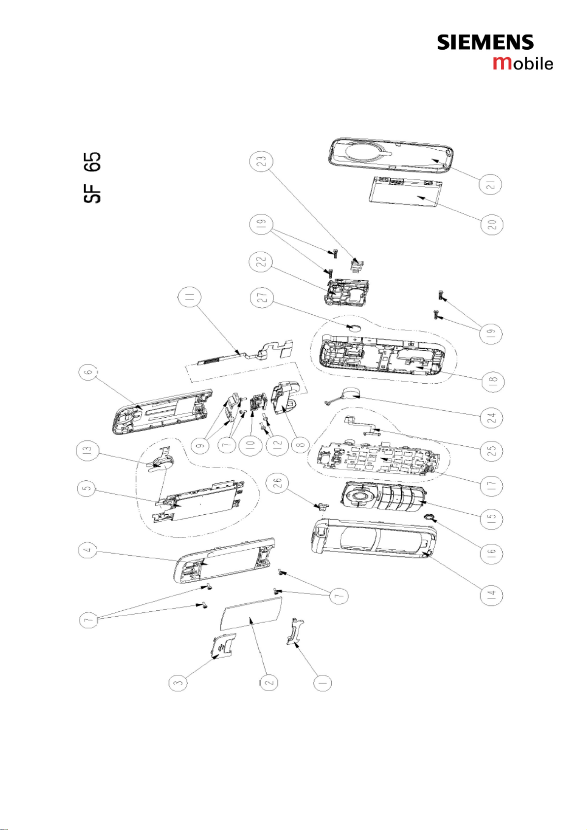
4. Exploded View
Company Confidential
Copyright 2005© Siemens AG
Page 7of 20
Service Repair Documentation
Level 2 – SF65

Company Confidential
Copyright 2005© Siemens AG
Page 8of 20
Service Repair Documentation
Level 2 – SF65
Ref. Nr. Description Part Number R. Level Qty
1 Menu Key SF65 Silver L50658-A157-A1 1 1
2 Display Window SF65 L50658-A157-A2 1 1
3 Switch Zoom Key SF65 silver L50658-A157-A3 1 1
4 Flip Frontcase without Earphone SF65
polar white L60658-A157-A4 1 1
5 LCD Module Assy with Earphone SF65 L50680-Q7360-M1 1 1
6 Flip Rearcase SF65 Polar White L60658-A157-A5 1 1
7 Screw 14X4 Torx Plus 6IP silver SF65 L50658-A157-A6 1 6
8 Hinge Body SF65 polar white L50658-A157-A7 1 1
9 Hinge Cover SF65 polar white L50658-A157-A8 1 2
10 Rotary Metal Hinge SF65 L50658-A157-A9 1 1
11 Flexible PCB Assembly SF65 L50680-Q7360-F1 1 1
12 Screw Torx Plus-6IP M1.6X4.4mm SF65 L50658-A157-A10 1 2
13 Earphone SF65 L50604-F3090-X923 2.5 1
14 Base Upper Case Shell without keypad
SF65 polar white L50658-A157-A11 1 1
15 Keypad SF65 polar white L50658-A157-A12 1 1
16 Microphone SF65 L50654-Z6-C117 1 1
17 RF Control Board Sf65 w. Camera Flash L36880-Q7360-U10 2 1
18 Mounting Frame with Camera Glass,w/o
Vibra,w/o Camera Gasket SF65 silver L50658-A157-A19 1 1
19 Screw Torx Black SF65 L50658-A157-A14 1 4
20 Battery Li-Ion 660 mAh SF65 L50645-K1310-X319 0 1
21 Battery Cover SF65 polar white L50658-A157-A15 0 1
22 Antenna with Connectors SF65 L50651-Z1901-A57 1 1
23 Camera Gasket SF65 L50658-A157-A16 1 1
24 Vibra Unit SF65 L50653-Z5-C302 1 1
25 Flexible Camera Flash Assembly SF 65 L50680-Q7360-F2 2.5 1
26 Base Upper Case Cap SF65 polar white L50658-A157-A17 1 1
27 Camera Glass Assembly SF65 L50658-A157-A18 1 1
IRDA Communication Module SF65 L50610-U6189-D670 2.5 1
Sensor Hall SF65 L50610-U6190-D670 2.5 2
Side Tact Switch SF65 L50615-Z77-C257 2.5 3
Backup Battery SF65 L50628-F2705-Z1 2.5 1
Display Connector – Board to Board
Connector SF65 L50634-Z97-C58 2.5 2
Battery Connector SF65 L50634-Z97-C59 2.5 1
Vibra Connector SF65 L50634-Z97-C63 2.5 1
System Connector SF65 L50634-Z97-C64 2.5 1
White Led SF65 L50640-L2119-D670 2.5 8
LED Red/Green Light Design SF65 L50640-L2125-D670 2.5 1

Company Confidential
Copyright 2005© Siemens AG
Page 9of 20
Service Repair Documentation
Level 2 – SF65
5. Disassembly of SF65
Note: ESD concept; the internal circuits will be more susceptible to ESD during the housing
exchange.The construction of the internal block is designed , in the best possible way, to protect
the circuit against sparks.
The keypad must be completely closed to prevent any occurence of an ESD disruptive discharge.
It is a requirement for the service personnel to observe ESD protection rules while performing
service on SF65.
Disassembly tools :
Name Part Number
Tweezers XXXXXXXXXXXX
Torque-Screwdriver F30032-P228-A1
Opening tool F30032-P38-A1
Hinge Tool CF62 F30032-P371-A1

Company Confidential
Copyright 2005© Siemens AG
Page 10 of 20
Service Repair Documentation
Level 2 – SF65
Release the battery cover (using your finger)
Shift the cover (be careful with plastic pin )
Take out the battery pack by releasing the 2
fingers from their catchs and lifting the battery
Upward from the strip.
Remove the menu key by lifting it upward with
a plastic tool
Remove the zoom key by lifting it upward
Unscrew the four screws of the flip front case

Company Confidential
Copyright 2005© Siemens AG
Page 11 of 20
Service Repair Documentation
Level 2 – SF65
Separate the flip front case from the flip
rearcase
Open the covers (be careful, earphone is
sticked on the top and bottom)
Unscrew the two screws of the LCD module
Lift the LCD module, unplug the flexible PCB
assembly on the bottom side
Unscrew the four screws of the mounting frame
Release the antenna with connectors by
pushing the antenna fixing fingers

Company Confidential
Copyright 2005© Siemens AG
Page 12 of 20
Service Repair Documentation
Level 2 – SF65
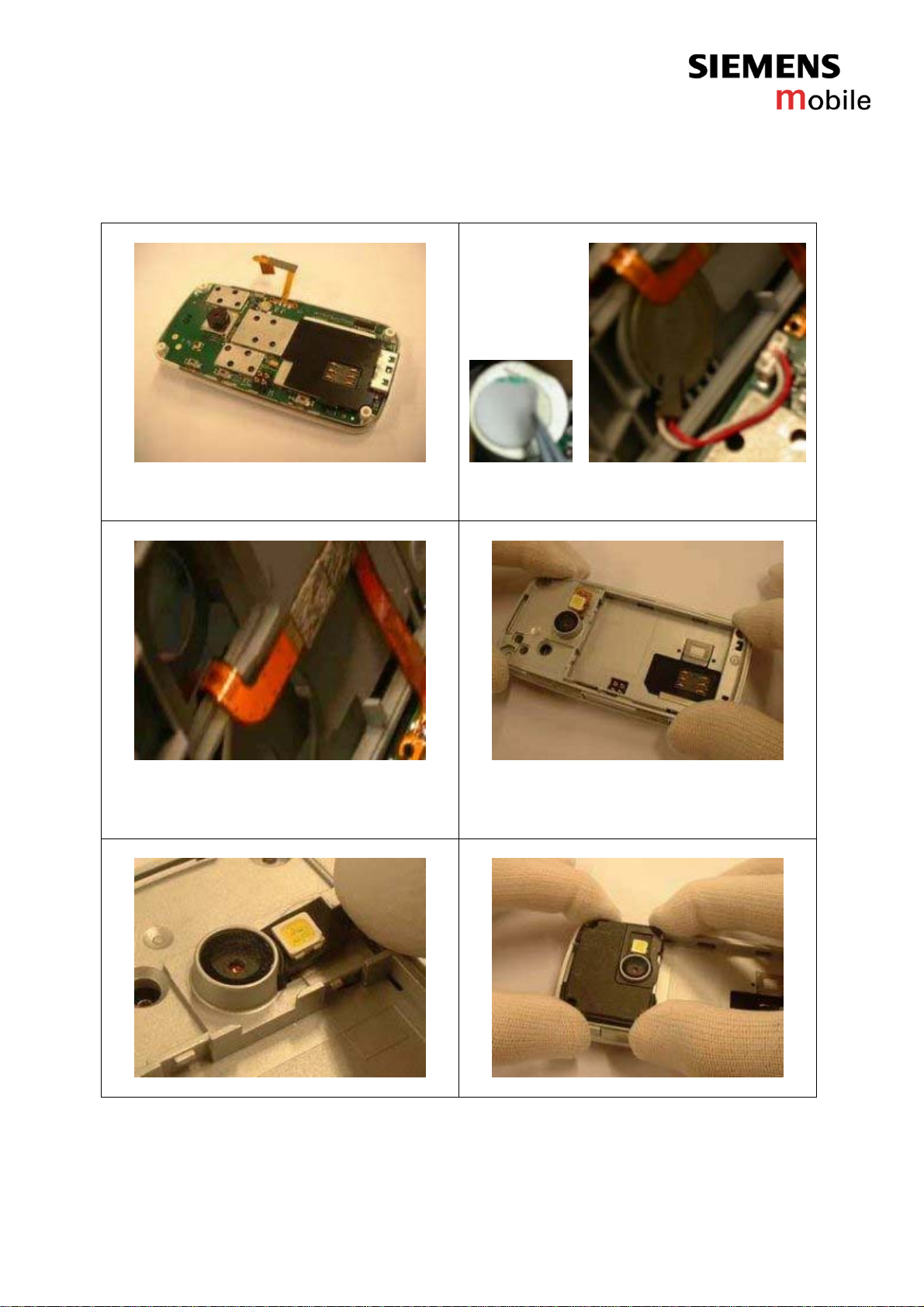
Take out the camera gasket with tweezers
Take apart the mounting frame from the base
upper case shell ( Attention to the flexible
camera flash assembly and the vibrator
connection)
Remove the PCB assembly by lifting it straight
up
Remove the vibrator from the Mounting frame
Place the hinge assembly tool into body
hinge´s hole, against the springhead and push
it in
Hold spring compressed in the hinge. When
the hinge is released, remove the hinge body
Company Confidential
Copyright 2005© Siemens AG
Page 13 of 20
Service Repair Documentation
Level 2 – SF65
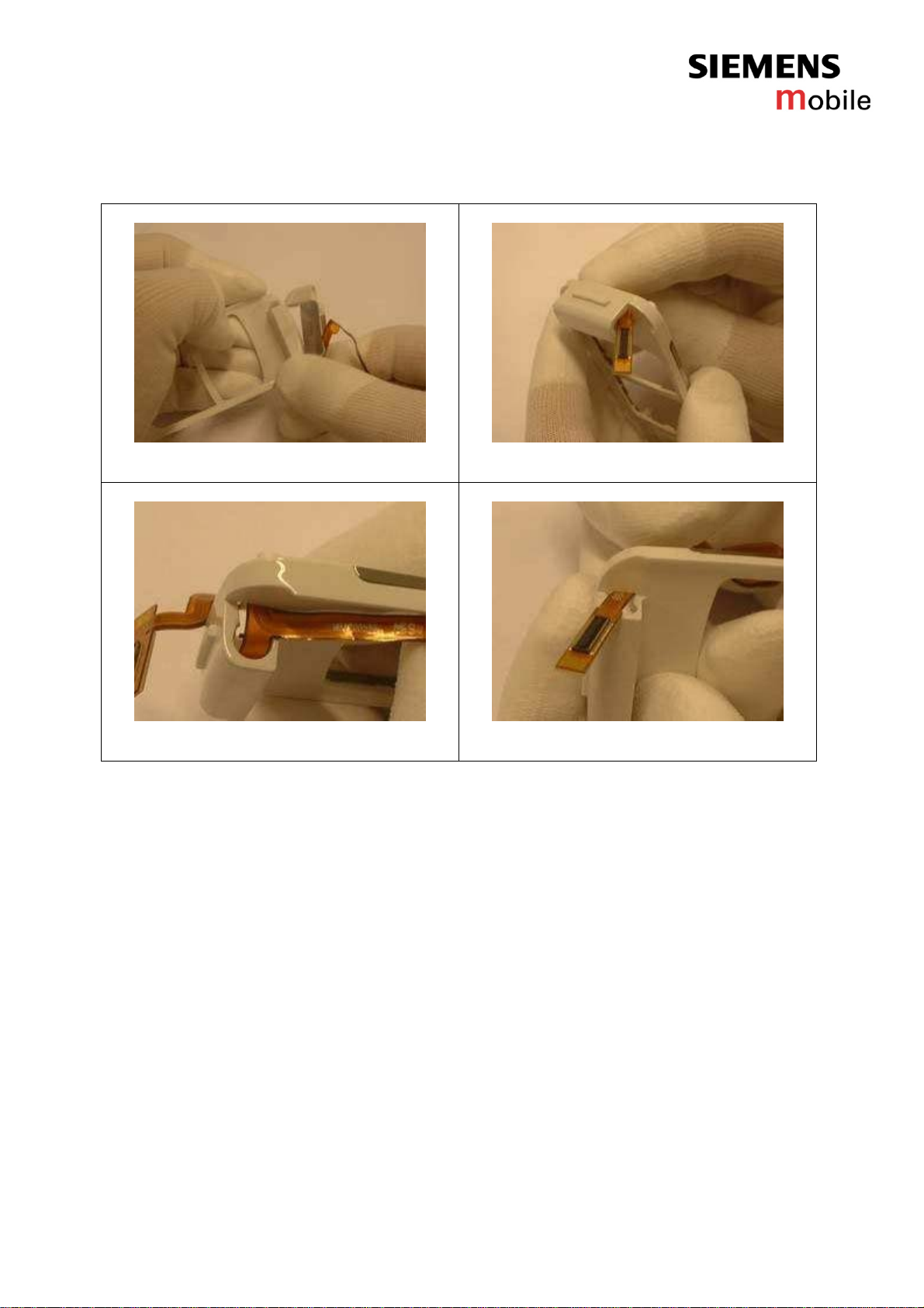
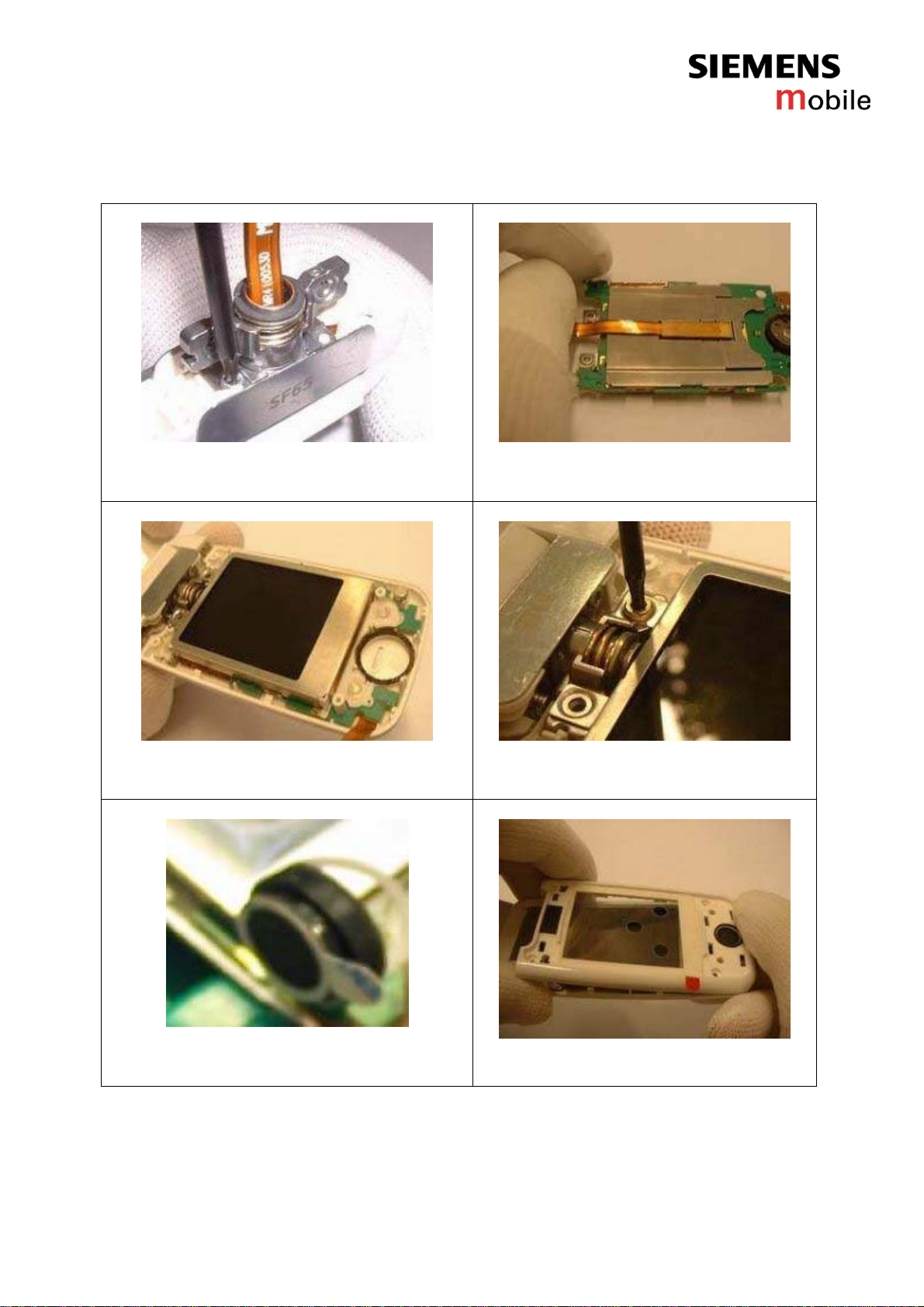
Carefully pull out the flex (pay attention not to
damage it )
Direction of the flex cable : down to up
If necessary push with a plastic tool to release
the flex cable
Removal of the flex cable
Company Confidential
Copyright 2005© Siemens AG
Page 14 of 20
Service Repair Documentation
Level 2 – SF65
6. Assembly of SF65
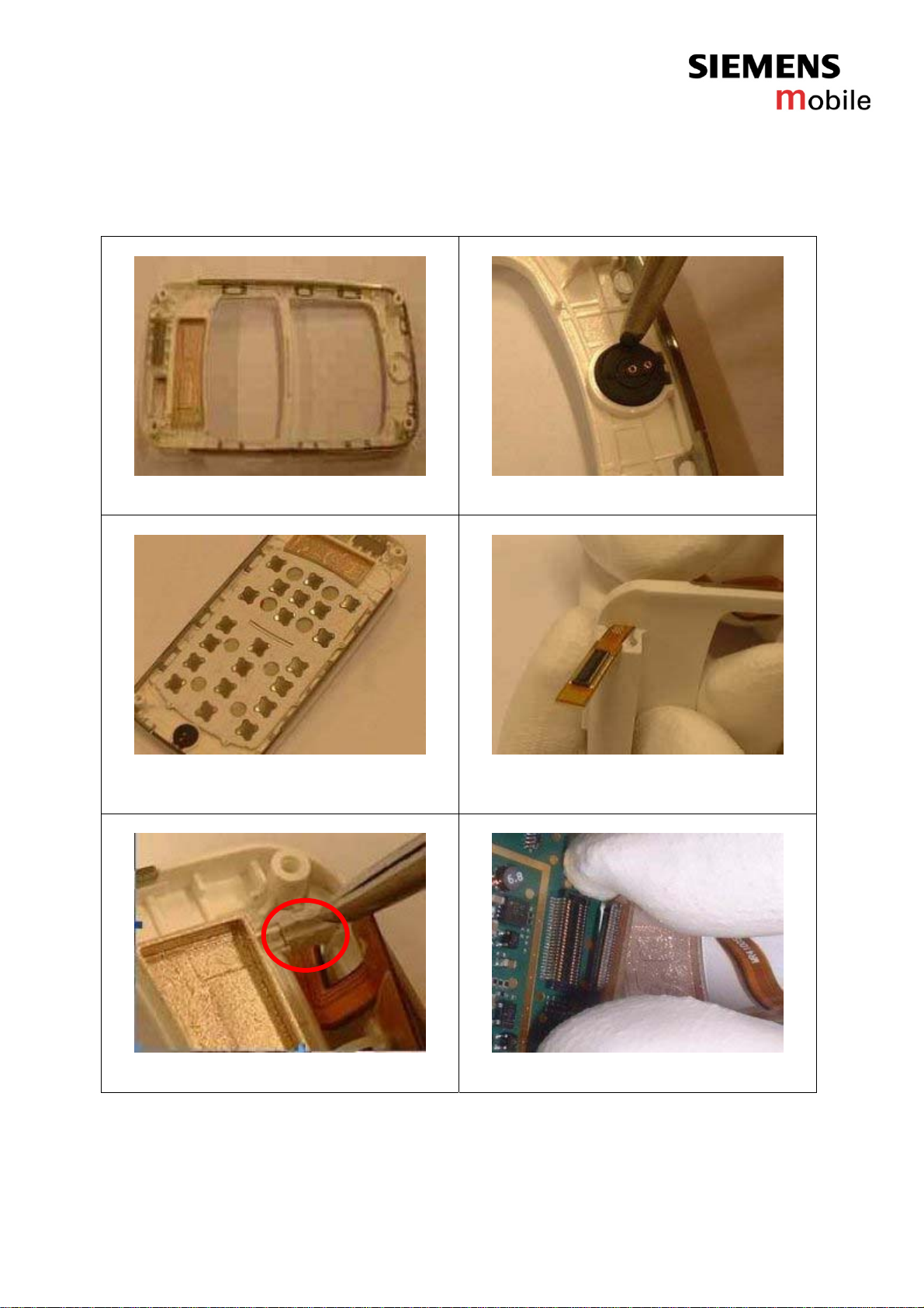
Place the Base Upper Case Shell on a flat
place
Place the microphone with tweezers
Take a new keypad,remove the safety foil,
place it into base upper case shell, taking care
of the 8 positionning pins
Insert the flex cable into the base upper case
shell
Place the white cap next to the screw bording
Plug the flexible PCB assembly into the
B2B connector
Company Confidential
Copyright 2005© Siemens AG
Page 15 of 20
Service Repair Documentation
Level 2 – SF65
Place the PCB assembly into the base upper
case shell
Remove the foil from the vibrator and stick it
into the mounting frame
Connect the vibrator to the PCB assembly
Thread in the flexible camera flash assembly to
the mounting frame
Adjust the flex camera flash
Clamp together the phone, press in the middle
and then on the four corners to avoid breaking
side buttons
Place the camera gasket on the flashlight
Clamp the antenna onto its place

Company Confidential
Copyright 2005© Siemens AG
Page 16 of 20
Service Repair Documentation
Level 2 – SF65
Screw the four black screws (M1.8*6.5 Screw
Torx black SF65) of the mounting frame
Torque : 18 cNm
Thread in the flexible PCB assembly into the
hinge body
Lift the Hinge Body on the edge of the Base Upper Case Shell.
With the help of a screw driver clamp the Hinge body to its place
Clamp the Hinge Body parallel with the phone
Bend in the flex to the hinge body anti-clockwise
( using tweezers)
Thread in the flex, place the rotary hinge
metal in such a way that it musn´t get to the
side of the keypad with its arched surface
Company Confidential
Copyright 2005© Siemens AG
Page 17 of 20
Service Repair Documentation
Level 2 – SF65
Fix the rotary metal hinge with the two silver
screws (M1.4*4 screws silver SF65)
Torque : 9 cNm
Connect the flexible PCB assembly to the
LCD and fix it ( Check the connection
carefully)
Place the LCD module into the flip rearcase
The LCD module has to be seated into the
positionning points
Screw in the LCD module
(M1.6*4.4 screws Yellow)Torque : 9 cNm
Remove the safety foil from the inner side of the
earphone, stick it into its place
Place the flip front housing and press hefty
( press on top , then bottom and middle )
Company Confidential
Copyright 2005© Siemens AG
Page 18 of 20
Service Repair Documentation
Level 2 – SF65
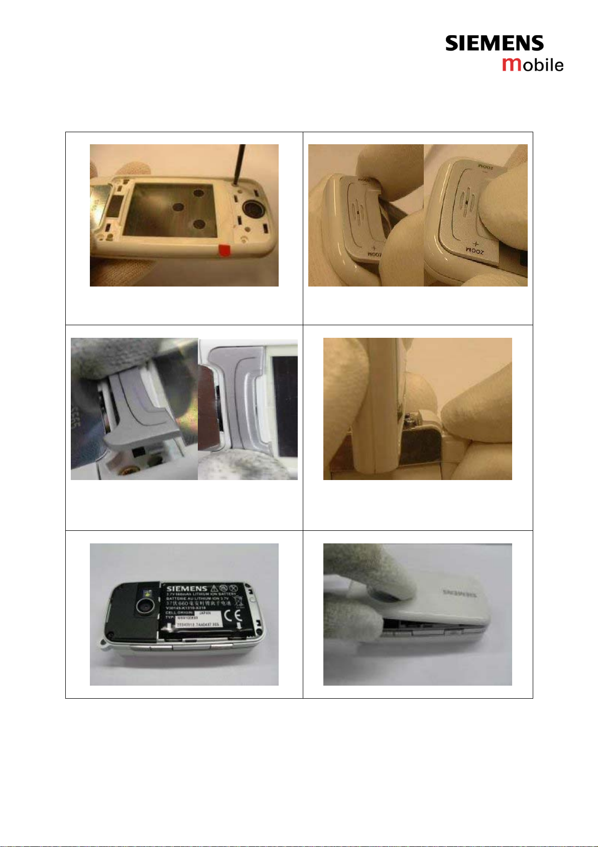
Screw together ( the screwing has to be done
cornerwise)
(M1.4*4 Screws black SF65)Torque : 10 cNm
Place the upper part of the zoom key and then
press hefty to fix it.
Place the menu key and press strongly
( Take care not to break down the snapping
fingers)
Turn the flip of the phone by 90°
Place the two hinge covers into their place
Insert the battery as shown
Snap on the battery cover

Company Confidential
Copyright 2005© Siemens AG
Page 19 of 20
Service Repair Documentation
Level 2 – SF65
7. IMEI Label Description
White label with black lettering
SIEMENS
S30880-SXXXX-XXXX-1 YY
XXXXXXXX SSSSSS C
Made xx Xxxxxxx
3)
SF65
1) 2)
4)
5)
6)
7)
8)
8)XXXXXXXX Typ-Approval Code TAC
8)SSSSSS Current serial number (6 digit),Assigned by PICS
8)C CHECK DIGIT 15.digit
1) Corporate logo :
2) Product name :
3) Made in Hungary :
4) Code of date : (See table below)
5) Code number of Transceiver
6) CE-identification :
7) Barcode IMEI-No.:
8) IMEI-No. (plain writing)
Explanation of Code of date
Year Date Code Month Date Code
2003 R January 1
2004 S February 2
2005 T March 3
2006 U September 9
2007 V October O
2008 W November N
2009 X December D
Company Confidential
Copyright 2005© Siemens AG
Page 20 of 20
Service Repair Documentation
Level 2 – SF65
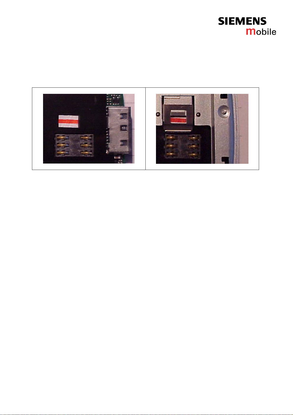
8. Water Indicator
• Water-indicator on main board
•
Water-indicator visible through holder window
The position of the Water-Indicator had been defined the way that it is possible
to read out the status of the water-Indicator within level0.In case that a walk-in
shop has been used as service-channel, the endcustomer shall be confronted
directly – if colour of Water-Indicator has turned to pink! In a further step the
mainboard shall be checked for any signs of oxidation.The result shall be used
as proof of evidence towards the endcustomer.In that case the mobile phone
shall not be accepted as in-warranty,but shall be considered as Damage
Caused by customer.
Other manuals for SF65
1
Table of contents
Other Siemens Mobile Cell Phone manuals

Siemens Mobile
Siemens Mobile A65 User manual

Siemens Mobile
Siemens Mobile CFX 65 Setup guide

Siemens Mobile
Siemens Mobile SK65 User manual

Siemens Mobile
Siemens Mobile C65 User manual

Siemens Mobile
Siemens Mobile CX65 User manual

Siemens Mobile
Siemens Mobile CFX 65 Setup guide

Siemens Mobile
Siemens Mobile SF65 Setup guide


