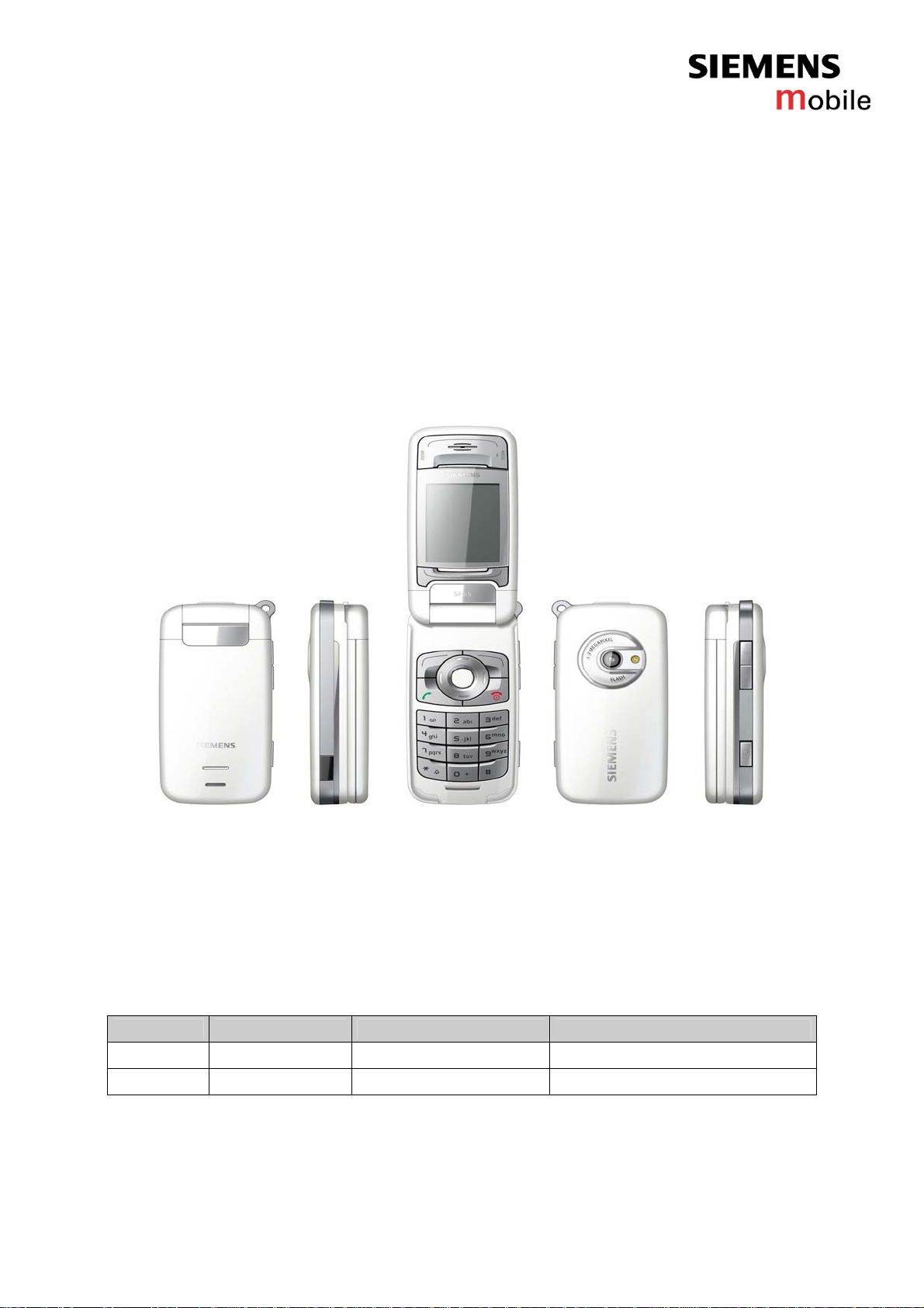
Siemens Mobile SF65 Setup guide
Company Confidential
Copyright 2005© Siemens AG
Page 1of 16
Service Repair Documentation
Level 2.5 – SF65
Service Repair Documentation
Level 2.5 – SF65
Release Date Department Notes to change
1.0 05.01.2005 COM MD CC GRM T New document
1.1 27.01.2005 COM MD CC GRM T IRIS codes reviewed

Company Confidential
Copyright 2005© Siemens AG
Page 2of 16
Service Repair Documentation
Level 2.5 – SF65
Introduction
This Service Repair Documentation is intended to carry out repairs on Siemens
repair level 2.5. The described failures shall be repaired in Siemens authorized local
workshops.only
All repairs have to be carried out in an ESD protected environment and with ESD
protected equipment/tools. For all activities the international ESD regulations have to
be considered.
Assembling/disassembling has to be done according to the latest SF65 Level 2 repair
documentation. It has to be ensured that every repaired mobile Phone is checked
according to the latest released General Test Instruction document (both documents
are available in the Technical Support section of the C-market).
Check at least weekly C-market for updates and consider all SF65 related Customer
Care Information
If you have any questions regarding the repair procedures or technical questions
spare not hesitate to contact our technical support team in Kamp-Lintfort, Germany:
Tel.: +49 2842 95 4666
Fax: +49 2842 95 4302

Company Confidential
Copyright 2005© Siemens AG
Page 3of 16
Service Repair Documentation
Level 2.5 – SF65
Table Of Content
1. SF65 Board Layout ..............................................................................................4
2. System Connector ................................................................................................6
3. Display Connector – Board to Board Connector ...................................................7
4. Battery Connector .................................................................................................8
5. White & Red/Green LED.......................................................................................9
6. IRDA Communication Module.............................................................................10
7. Back Up Battery ..................................................................................................11
8. Side TACT Switch...............................................................................................12
9. Sensor Hall .........................................................................................................13
10. Vibra Connector ..................................................................................................14
11. Earphone ............................................................................................................15
12. Flexible Camera Flash Assembly.......................................................................16
Company Confidential
Copyright 2005© Siemens AG
Page 4of 16
Service Repair Documentation
Level 2.5 – SF65
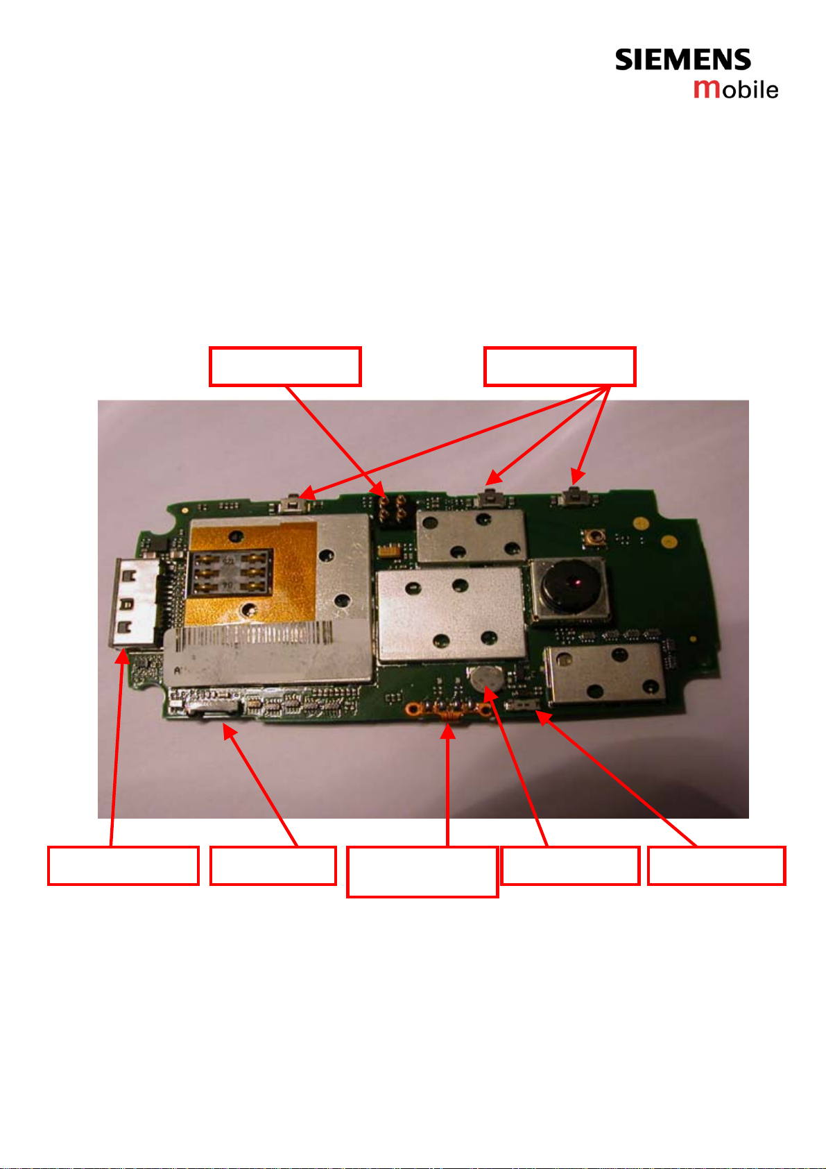
1. SF65 Board Layout
Jigs, Tools and Working materials for all described repairs:
- hot air blower
- soldering gun
- tweezers
- flux
- solder
Battery Connector
Vibra ConnectorBack Up Battery
Flexible Camera
Flash Assembly
IRDA ModuleSystem Connector
Side TACT Switch

Company Confidential
Copyright 2005© Siemens AG
Page 5of 16
Service Repair Documentation
Level 2.5 – SF65
Sensor Hall
White LED
Earphone Red/Green LED Display Connector
Board to Board Connector
Other manuals for SF65
1
Table of contents
Other Siemens Mobile Cell Phone manuals

Siemens Mobile
Siemens Mobile SK65 User manual

Siemens Mobile
Siemens Mobile C65 User manual

Siemens Mobile
Siemens Mobile CFX 65 Setup guide

Siemens Mobile
Siemens Mobile A65 User manual

Siemens Mobile
Siemens Mobile CX65 User manual

Siemens Mobile
Siemens Mobile CFX 65 Setup guide

Siemens Mobile
Siemens Mobile SF65 Setup guide


