Siemens Mobile CFX 65 Setup guide

Company Confidential
Copyright 2004© Siemens AG
1
Service Repair Documentation
Level 2.5 - CFX65 V1.1
Service Repair Documentation
Level 2.5 – CFX 65
Release Date Department Notes to change
1.0 10.11.2004 ICM MP CCQ GRM T New document
1.1 09.12.2004 ICM MP CCQ GRM T Code Changes

Company Confidential
Copyright 2004© Siemens AG
2
Service Repair Documentation
Level 2.5 - CFX65 V1.1
Introduction
This Service Repair Documentation is intended to carry out repairs on Siemens
repair level 2.5. The described failures shall be repaired in Siemens authorized
local workshops only.
All repairs have to be carried out in an ESD protected environment and
with ESD protected equipment/tools. For all activities the international
ESD regulations have to be considered.
Assembling/ disassembling has to be done according to the latest CFX65 Level 2
repair documentation. It has to be ensured that every repaired mobile phone is
checked according to the latest released General Test Instruction document
(both documents are available in the Technical Support section of the C-market).
If you have any questions regarding the repair procedures or technical questions
do not hesitate to contact our technical support team in Kamp-Lintfort, Germany:
Scrap Handling: All Scrap information given in this manual
are related to the SCRAP-Rules and instructions.
Attention: Consider soldering rules, avoid excessive heat
Tel.: +49 2842 95 4666
Fax: +49 2842 95 4302

Company Confidential
Copyright 2004© Siemens AG
3
Service Repair Documentation
Level 2.5 - CFX65 V1.1
Table of content
CFX 65 BOARD LAYOUT ...................................................................................................................... 4
LCM LAYOUT......................................................................................................................................... 6
1. B TO B CONNECTOR (J305) .......................................................................................................... 7
2. RF SWITCH (ANT300) ..................................................................................................................... 8
3. ANTENNA SPRING (J301) .............................................................................................................. 9
4. SPEAKER CONNECTOR (J200)................................................................................................... 10
5. SIDE KEY SWITCH (S400,S401)................................................................................................... 11
6. SIM READER (J302)...................................................................................................................... 12
7. I/O CONNECTOR (J304)................................................................................................................ 13
8. BACKUP BATTERY (BT414R)...................................................................................................... 14
9. IRDA (U103) ................................................................................................................................... 15
10. BATTERY CONNECTOR (J300).................................................................................................... 16
11. FUSE (F300).................................................................................................................................... 17
12. LED ON PCBA................................................................................................................................18
13. CAMERA CONNECTOR................................................................................................................. 19
14. CAMERA MODULE ........................................................................................................................ 20
15. FLASH LED..................................................................................................................................... 21

Company Confidential
Copyright 2004© Siemens AG
4
Service Repair Documentation
Level 2.5 - CFX65 V1.1
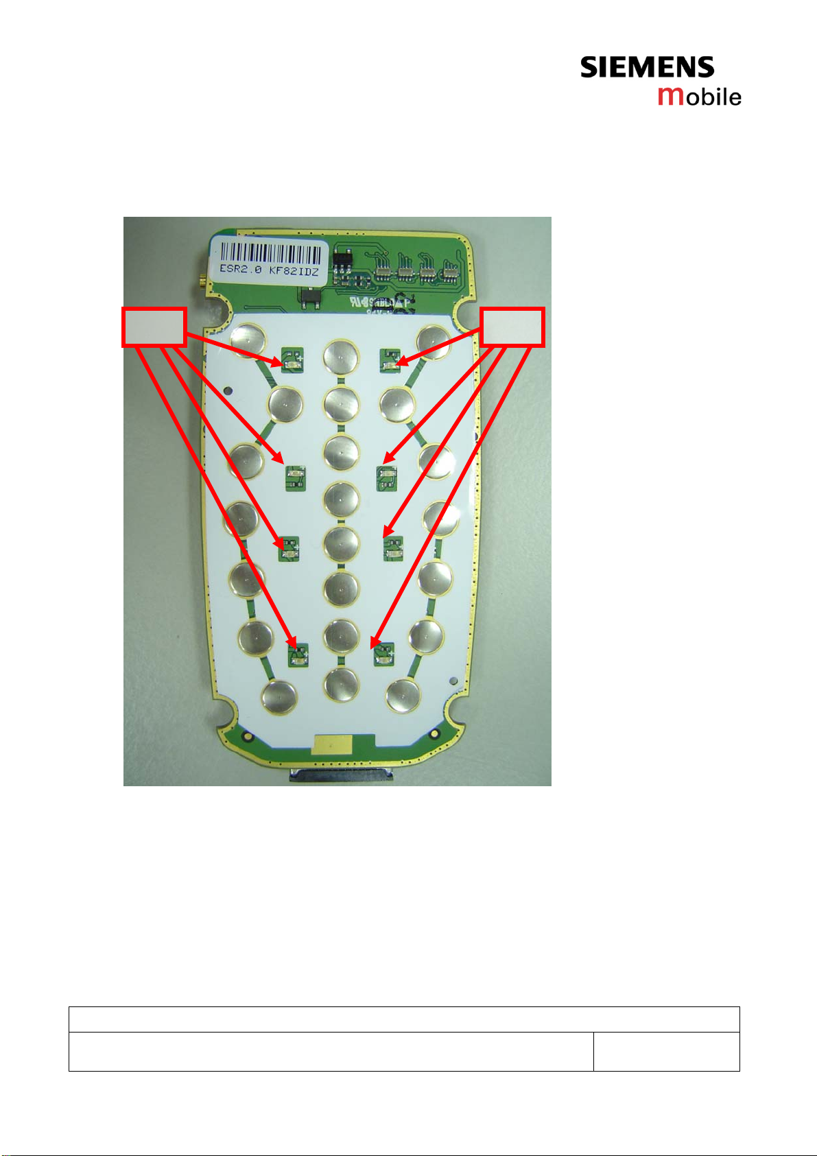
CFX 65 board layout
Jigs, Tools and working materials for all described repairs:
-hot air blower
-soldering iron
-a pair of tweezers
-flux
-solder
(J300)
Battery
c
onnector
(J200)
Buzzer
connector
(J302) SIM
connector
(F300) Fuse
(J304) I/O
connector
(BT414R)
Backup
battery
(U103) IrDA
(S402)
Switch
(ANT330) RF
connector
(J301) RF
switch
(S401)
Switch
(J305) B to B connector
Company Confidential
Copyright 2004© Siemens AG
5
Service Repair Documentation
Level 2.5 - CFX65 V1.1
LED LED
Company Confidential
Copyright 2004© Siemens AG
6
Service Repair Documentation
Level 2.5 - CFX65 V1.1
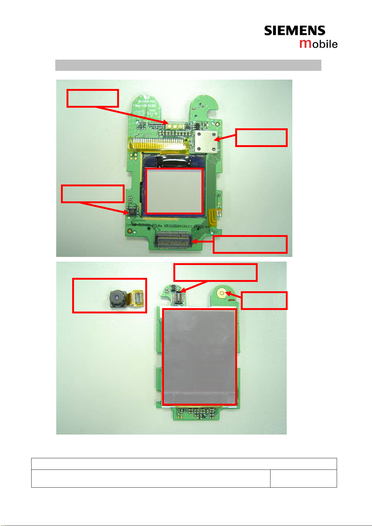
LCM layout
Charge pump
Mono LCM
Flash LED
Backend
B to B connector
65K LCM
Receiver
Camera connector
Camera module

Company Confidential
Copyright 2004© Siemens AG
7
Service Repair Documentation
Level 2.5 - CFX65 V1.1
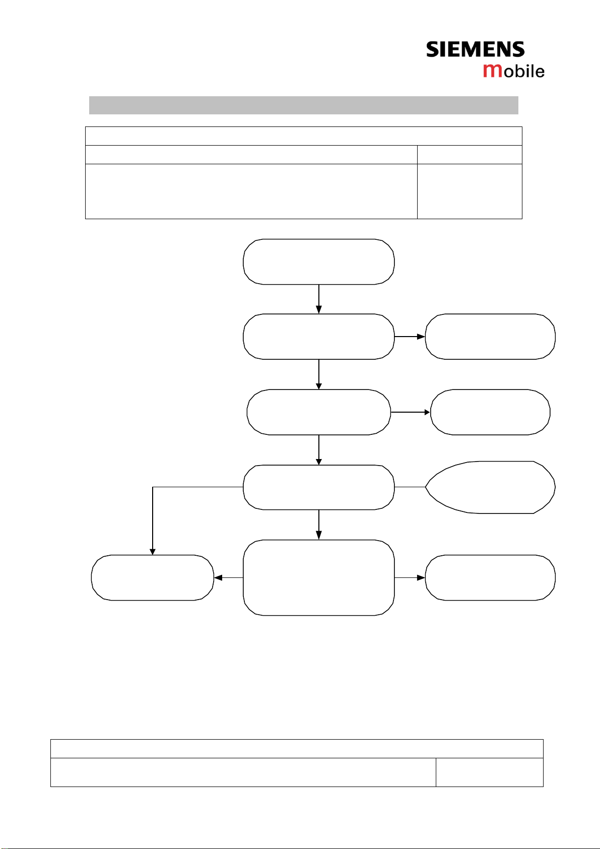
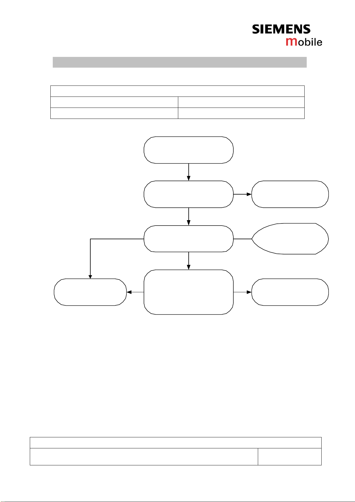
1. B to B connector (J305)
Fault Symptoms
Customer GRT
No display but main board works No GRT support
Camera and/ or earpiece does not work
Level2Repair
Check the status of the
B to B connector visually
- check for twisted or
bendedcontacts
- check for dry joints
B to B connector problems
Watch for oxidation and
damaged padsof the
B to B connector
SCRAP
Exchange
BtoBconnector
okay
okay
not
okay
not okay
-hastobe send
separatelytoWSC
Connector board to board
Use soldering iron to remove defective component. Avoid excessive heat! Watch surrounding
components! Resolder new component afterwards.
E-commerce order number: L50634-Z97-C377
Soldering temperature: 240 - 255°C
IRIS Diagnose Code: BA000 Accessories Camera
21000 Display Performance
22000 Display Background Illumination

Company Confidential
Copyright 2004© Siemens AG
8
Service Repair Documentation
Level 2.5 - CFX65 V1.1
2. RF switch (ANT300)
Fault Symptoms
Customer GRT
Network search No GRT support
No location update No GRT support
Use the resistor test
function of a multimeter
to check connection
between springcontacts
and solderingcontacts.
The value must be ~0Ω
Check the status of the
RFconnectorvisually
- check for twisted or
bendedcontacts
- check for dry joints
RFconnectorproblems
Watch for oxidation and
damaged padsof the
RFconnector
SCRAP -hastobe send
separatelytoWSC
Level2Repair
Exchange
batteryconnector
okay
okay
okay
not
okay
not
okay
not okay
Check for dust inside
the RFconnector Clean
IOconnector
okay
not
okay
Connector RF
Use hot air blower to remove defective component. Avoid excessive heat! Watch surrounding
components! Resolder new component afterwards.
E-commerce order number: L50634-Z97-C375
Soldering temperature: 240 - 255°C
IRIS Diagnose Code: 45100 Interface / Antenna connector / No function

Company Confidential
Copyright 2004© Siemens AG
9
Service Repair Documentation
Level 2.5 - CFX65 V1.1
3. Antenna Spring (J301)
Fault Symptoms
Customer GRT
Poor network No GRT support
No network No GRT support
Use the resistor test
function of a multimeter
to check connection
between springcontacts
and solderingcontacts.
The value must be ~0Ω
Check the status of the
Antennaspringvisually
- check for twisted or
bendedcontacts
- check for dry joints
Antennaspringproblems
Watch for oxidation and
damaged padson the
PCB
SCRAP -hastobe send
separatelytoWSC
Level2Repair
Exchange
Antennaspring
okay
okay
okay
not
okay
not
okay
not okay
Check for dust inside
theAntennaspring Clean
IOconnector
okay
not
okay
Antenna Spring
Use hot air blower to remove defective component. Avoid excessive heat! Watch surrounding
components! Resolder new component afterwards.
E-commerce order number: L50658-A136-B16
Soldering temperature: 240 - 255°C
IRIS Diagnose Code: 83140 TX power fault internal antenna

Company Confidential
Copyright 2004© Siemens AG
10
Service Repair Documentation
Level 2.5 - CFX65 V1.1
4. Speaker connector (J200)
Fault Symptoms
Customer GRT
No sound from speaker No GRT support
The speaker is sometimes barely to hear No GRT support
Use the resistor test
function of a multimeter
to check connection
between springcontacts
and solderingcontacts.
The value must be ~0Ω
Check the status of the
Speakerconnectorvisually
- check for twisted or
bendedcontacts
- check for dry joints
Speakerconnector
problems
Watch for oxidation and
damaged padson the
Speakerconnector
SCRAP -hastobe send
separatelytoWSC
Level2Repair
Exchange
Speakerconnector
okay
okay
okay
not
okay
not
okay
not okay
Check for dust inside
theSpeakerconnector Clean
IOconnector
okay
not
okay
Speaker connector
Use soldering iron to remove defective component. Avoid excessive heat! Watch surrounding
components! Resolder new component afterwards.
E-commerce order number: L50634-Z97-C381
Soldering temperature: 240 - 255°C
IRIS Diagnose Code: 72110 Accustics

Company Confidential
Copyright 2004© Siemens AG
11
Service Repair Documentation
Level 2.5 - CFX65 V1.1
5. Side key switch (S400,S401)
Fault Symptoms
Customer GRT
No function while pressing No GRT support
Pressing feeling is bad No GRT support
Use the resistor test
function of a multimeter
to check connection
between springcontacts
and solderingcontacts.
The value must be ~0Ωwhen
switch is pressed.
Check the status of the
Side key switch visually
- check for twisted or
bendedcontacts
- check for dry joints
Side key switch
problems
Watch for oxidation and
damaged padson the
Side key switch
SCRAP -hastobe send
separatelytoWSC
Level2Repair
Exchange
Side keyswitch
okay
okay
okay
not
okay
not
okay
not okay
Check for dust inside
the Side key switch
Clean
IOconnector
okay
not
okay
Side key switch
Use hot air blower to remove defective component. Avoid excessive heat! Watch surrounding
components! Resolder new component afterwards.
E-commerce order number: L50615-Z77-C240
Soldering temperature: 240 - 255°C
IRIS Diagnose Code: 34100 Keys / Side

Company Confidential
Copyright 2004© Siemens AG
12
Service Repair Documentation
Level 2.5 - CFX65 V1.1
6. SIM reader (J302)
Fault Symptoms
Customer GRT
Handset does not accept SIM No GRT support
Can not read SIM No GRT support
Use the resistor test
function of a multimeter
to check connection
between springcontacts
and solderingcontacts.
The value must be ~0Ω
Check the status of the
SIM Cardreader visually
- check for twisted or
bendedcontacts
- check for dry joints
SIM Card Problems
Watch for oxidation and
damaged padsof the
SIM Cardreader
SCRAP -hastobe send
separatelytoWSC
Level2Repair
Exchange
SIM Cardreader
okay
okay
okay
not
okay
not
okay
not okay
SIM Reader
Use soldering iron to remove defective component. Avoid excessive heat! Watch surrounding
components! Resolder new component afterwards.
E-commerce order number: L50634-Z97-C374
Soldering temperature: 240 - 255°C
IRIS Diagnose Code: 43300 Interface / SIM Cardreader / Mechanical Damage
Company Confidential
Copyright 2004© Siemens AG
13
Service Repair Documentation
Level 2.5 - CFX65 V1.1
7. I/O connector (J304)
Fault Symptoms
Customer GRT
Charging problems No GRT support
Problems with external loudspeaker or microphone when using a car kit No GRT support
Problems with accessories connected at the I/O connector No GRT support
Use the resistor test
function of a multimeter
to check connection
between springcontacts
and solderingcontacts.
The value must be ~0Ω
Check the status of the
IO connectorvisually
- check for twisted or
bendedcontacts
- check for dry joints
IO connectorproblems
Watch for oxidation and
damaged padsof the
IOconnector
SCRAP -hastobe send
separatelytoWSC
Level2Repair
Exchange
IOconnector
okay
okay
okay
not
okay
not
okay
not okay
Check for dust inside
the IO connector Clean
IOconnector
okay
not
okay
Use soldering iron to remove defective component. Avoid excessive heat! Watch surrounding
components! Resolder new component afterwards.
E-commerce order number: L50634-Z97-C375
Soldering temperature: 240 - 255°C
IRIS Diagnose Code: 46100 Interface/Charging connector/ Mechanical damage

Company Confidential
Copyright 2004© Siemens AG
14
Service Repair Documentation
Level 2.5 - CFX65 V1.1
8. Backup battery (BT414R)
Fault Symptoms
Customer GRT
After removing and reassembling the battery, the time is not
correct or default value. No GRT support
Use the voltage test
function of a multimeter
to check battery voltage
The voltage mustbe ~0Ω
Check the status of the
batteryand
connectorvisually
- check for twisted or
bendedcontacts
- check for dry joints
Backup Battery problems
Watch for oxidation and
damaged padsof the
batteryand
connector
SCRAP -hastobe send
separatelytoWSC
Level2Repair
Exchange
BackupBattery
okay
okay
okay
not
okay
not
okay
not okay
Backup battery
Use soldering iron to remove defective component. Avoid excessive heat! Watch surrounding
components! Resolder new component afterwards.
E-commerce order number: L50645-K1310-X320
Soldering temperature: 220 - 230°C
IRIS Diagnose Code: 16000 Battery / Backup Battery Performance
Company Confidential
Copyright 2004© Siemens AG
15
Service Repair Documentation
Level 2.5 - CFX65 V1.1
9. IRDA (U103)
Fault Symptoms
Customer GRT
No infrared connection possible No GRT support
Level2Repair
Check the status of the
IRDA visually
- check for twisted or
bendedcontacts
- check for dry joints
IRDAproblems
Watch for oxidation and
damaged padsof the
IRDA
SCRAP
Exchange
IRDA
okay
okay
not
okay
not okay
-hastobe send
separatelytoWSC
IRDA
Use hot air blower to remove defective component. Avoid excessive heat! Watch surrounding
components! Resolder new component afterwards.
E-commerce order number: L50610-U6153-D670
Soldering temperature: 240 - 255°C
IRIS Diagnose Code: 41000 Interfaces / IRDA / No function
41300 Interfaces / IRDA / Mechanical damage

Company Confidential
Copyright 2004© Siemens AG
16
Service Repair Documentation
Level 2.5 - CFX65 V1.1
10. Battery connector (J300)
Fault Symptoms
Customer GRT
Mobile does not switch on No GRT support
Use the resistor test
function of a multimeter
to check connection
between springcontacts
and solderingcontacts.
The value must be ~0Ω
Check the status of the
batteryconnectorvisually
- check for twisted or
bendedcontacts
- check for dry joints
Batteryconnectorproblems
Watch for oxidation and
damaged padsof the
batteryconnector
SCRAP -hastobe send
separatelytoWSC
Level2Repair
Exchange
batteryconnector
okay
okay
okay
not
okay
not
okay
not okay
Battery connector
Use hot air blower to remove defective component. Avoid excessive heat! Watch surrounding
components! Resolder new component afterwards.
E-commerce order number: L50634-Z97-C376
Soldering temperature: 240 - 255°C
IRIS Diagnose Code: 13000 Battery / Mechanical damage
Company Confidential
Copyright 2004© Siemens AG
17
Service Repair Documentation
Level 2.5 - CFX65 V1.1
11. Fuse (F300)
Fault Symptoms
Customer GRT
Battery charging does not work No GRT support
Use the voltage test
function of a multimeter
to check battery voltage
The voltage mustbe ~0Ω
Check the status of the
Fuse visually
- check for twisted or
bendedcontacts
- check for dry joints
Fuseproblems
Watch for oxidation and
damaged padson the
PCB
SCRAP -hastobe send
separatelytoWSC
Level2Repair
Exchange
Fuse
okay
okay
okay
not
okay
not
okay
not okay
Fuse
Use soldering iron to remove defective component. Avoid excessive heat! Watch surrounding
components! Resolder new component afterwards.
E-commerce order number: L50645-A820-Y20
Soldering temperature: 240 - 255°C
IRIS Diagnose Code: 11000 Battery / No charging / Deep discharge

Company Confidential
Copyright 2004© Siemens AG
18
Service Repair Documentation
Level 2.5 - CFX65 V1.1
12. LED on PCBA
Fault Symptoms
Customer GRT
LED does not work or not bright No GRT support
Use the diode test
function of a multimeter
to check the status of the
diode.Thetypicalvoltage
drop on the diode is 1.7 V
when testing the diode
functoin with the multimeter.
Check the status of the
LED pads visually
- check for twisted or
bendedcontacts
- check for dry joints
LED on PCBA problems
Watch for oxidation and
damaged padsof the
LED
SCRAP -hastobe send
separatelytoWSC
Level2Repair
ExchangeLED
okay
okay
okay
not
okay
not
okay
not okay
LED
Use soldering iron to remove defective component. Avoid excessive heat! Watch surrounding
components! Resolder new component afterwards.
E-commerce order number: L50640-L2123-D670
Soldering temperature: 240 - 255°C
IRIS Diagnose Code: 36000 Keys / Illumination

Company Confidential
Copyright 2004© Siemens AG
19
Service Repair Documentation
Level 2.5 - CFX65 V1.1
13. Camera connector
Fault Symptoms
Customer GRT
Camera malfunction No GRT support
Use the resistor test
function of a multimeter
to check connection
between springcontacts
and solderingcontacts.
The value must be ~0Ω
Check the status of the
cameraconnectorvisually
- check for twisted or
bendedcontacts
- check for dry joints
Cameraconnectorproblems
Watch for oxidation and
damaged padsof the
cameraconnector
SCRAP -hastobe send
separatelytoWSC
Level2Repair
Exchange
cameraconnector
okay
okay
okay
not
okay
not
okay
not okay
Camera connector
Use hot air blower to remove defective component. Avoid excessive heat! Watch surrounding
components! Resolder new component afterwards.
E-commerce order number: L50634-Z97-C378
Soldering temperature: 240 - 255°C
IRIS Diagnose Code: BA000 Accessories / Camera

Company Confidential
Copyright 2004© Siemens AG
20
Service Repair Documentation
Level 2.5 - CFX65 V1.1
14. Camera module
Fault Symptoms
Customer GRT
Camera malfunction No GRT support
Use the resistor test
function of a multimeter
to check connection
between springcontacts
and solderingcontacts.
The value must be ~0Ω
Check the status of the
camera modulevisually
- check for twisted or
bendedcontacts
- check for dry joints
Cameramoduleproblems
Watch for oxidation and
damaged padsof the
cameramodule
SCRAP -hastobe send
separatelytoWSC
Level2Repair
Exchange
cameramodule
okay
okay
okay
not
okay
not
okay
not okay
Camera module
Use hot air blower to remove defective component. Avoid excessive heat! Watch surrounding
components! Resolder new component afterwards.
E-commerce order number: L50653-Z5-C297
Soldering temperature: 240 - 255°C
IRIS Diagnose Code: BA000 Accessories / Camera
Other manuals for CFX 65
1
Table of contents
Other Siemens Mobile Cell Phone manuals

Siemens Mobile
Siemens Mobile C65 User manual

Siemens Mobile
Siemens Mobile CX65 User manual

Siemens Mobile
Siemens Mobile A65 User manual

Siemens Mobile
Siemens Mobile SF65 Setup guide

Siemens Mobile
Siemens Mobile SK65 User manual

Siemens Mobile
Siemens Mobile CFX 65 Setup guide

Siemens Mobile
Siemens Mobile SF65 Setup guide


