manuals.online logo
Brands
  1. Home
  2. •
  3. Brands
  4. •
  5. Siemens
  6. •
  7. Adapter
  8. •
  9. Siemens PC2637 User manual

Siemens PC2637 User manual

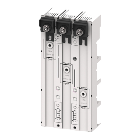
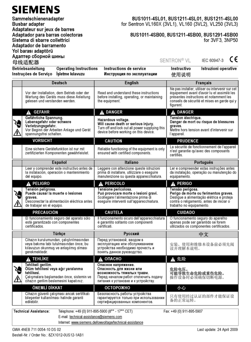
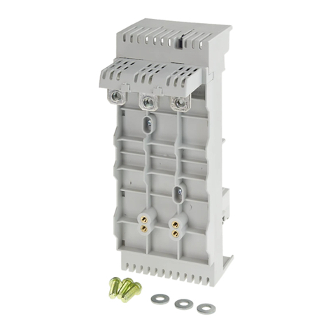
LineEnd LoadEnd Switchboard
Number Adapter Adapter Mtg. Plate
Application Poles Cat. No. Cat. No. Cat. No.
Information “E” “CLE”
2 PC2637 PC2638 PL2616 PL2617
3 PC2657 PC2658 PL2616 PL2617
3 PM2657 PM2658 PL2616 PL2617
Hazardous voltage.
Will cause death or
severe injury.
Turn power off supply-
ing device before
installing.
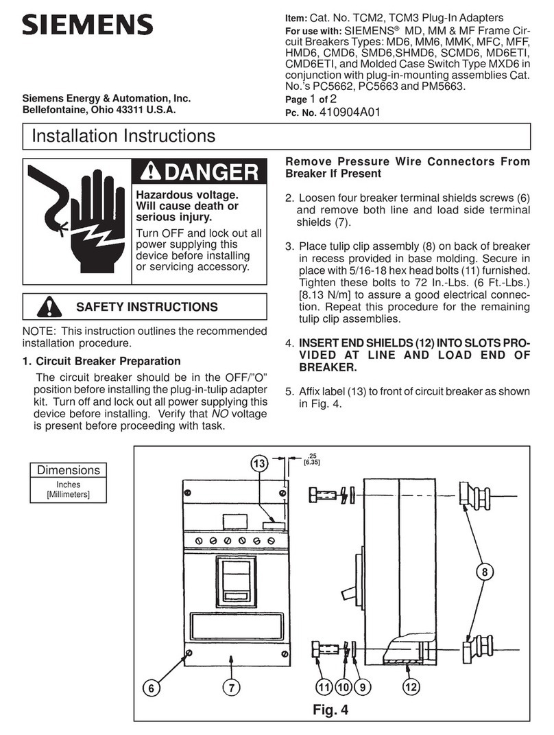
Item: InstructionsforInstallationofCircuitBreakerPlug-In
Adaptersfor“E”&“CLE”FrameCircuitBreakers
(Cat.No.’sPC2637,PC2638,PC2657,PC2658,PM2657,
PM2658)
For use with: SIEMENS®E, ED, EM and EF Frame Cir-
cuitBreakers andMolded CaseSwitches
Page 1 of 2
Pc. No. 60303A02
SAFETY INSTRUCTIONS
Siemens Energy & Automation, Inc.
Bellefontaine, Ohio 43311 U.S.A.
Installation Instructions
NOTE: This instruction outlines the recommended
installation procedure.
1. Turn power off supplying device before installing kit.
A complete plug-in installation requires one line end
adapter assembly (consisting of plug-in adapter, stud
connectors and associated hardware), one load end
adapter assembly and one switchboard mounting plate.
The switchboard mounting plate is optional and can be
replaced by other mounting means to suit customers’
requirements.
Mounting Preparation: (Figs. 1 & 2)
2. If the switchboard mounting plate (1) is to be used,
provided required drilling as shown in Fig. 1.
3. If other mounting means are to be used, provide
the cutouts and drilling required to mount the
adapter blocks as shown in Fig. 2.
Switchboard Mounting Plate (If used): (Fig. 3)
4. Place switchboard mounting plate (1) in position
at location previously prepared in step 1 above.
Secure in place with 1/4” [M6] hardware (Hard-
ware furnished by customer).
3.38
[85.8]
Fig. 2
Fig. 1
BREAKER A B C
E5
[127.01] 8
[203.2] 9
[228.6]
CLE 8.25
[209.55] 11.25
[285.75] 12.25
[311.2]
DIMENSIONS
INCHES
[MILLIMETERS]
.266[6.75] Dia.Hole
4 Pls. (For 1/4”[M6]
Mtg. Hardware)
.50
[12.7]
.56 [14.2]
Breaker Mtg.
Location
1.00
[25.4]
[50.8]
1.00
[25.4]
1.00
[25.4]
.99
[25.1]
.705
[17.90]
[35.18]
. 266 Dia. [6.75]
Hole
(4 Pls.)
.38 Rad. [9.6]
(4 Pls.)
Customer’s
Mtg. Sheet
(Optional)
Breaker Mtg.
Location
.99
[25.1]
BREAKERS TYPES
E2(-A),E4(-A),E6(-A),HE4(-A),HE6(-A),CLE(-A),ED2,
ED4,ED6,EM6,EMK,HED4,HED6,CED6,EFC,EFF
Siemens Energy & Automation, Inc.
Bellefontaine, OH 43311 U.S.A.
Installation Instructions
Hazardous voltage.
Will cause death or
severe injury.
Turn power off
supplying device before
installing.
Page 2 of 2
Pc. No. 60303A02
Plug-In Adapter: (Fig. 3)
5. Align plug-in adapter (2) with cutouts in switch-
board mounting plate (or customer’s mounting
means as previously prepared in step 2) and
secure in place with 1/4” screws (3) washers (4)
and(5)andhex nuts(6). Tighten to55±5In.-Lb.
[6.21N/m].
Final Assembly: (Fig. 6)
6.
Make bus and/or cable connection to rear
of mounting block studs using hex nuts (15)
furnished to secure this connection. Attach
bus or connector to mounting block studs
by removing one nut (15) from the top of
each stud. Do not allow this nut (15) to come
within 1/8 inch of the nut resting on the tower
(17). Do not tighten nut (17) as it is preset at
the factory. Secure the nut under the bus or
connector with a wrench to keep it from ro-
tating. Replace the nut (15) that you had
previously removed and torque to 35 ± 2
In.-Lb. [3.95 N/m] making certain not to al-
low the nut being retained with the wrench
to rotate.
CAUTION: Make certain that breaker operat-
inghandleisinthe Off position before proceed-
ing with the next step.
Breaker Preparation: (Fig. 4)
Remove Pressure Wire Connectors From
Breaker If Present
7. Select line side breaker stud and insulator (11)
and (12) and assemble to terminals, from back
ofbreaker, and securetobreakerterminalswith
#12-24 screw and washers (7), (8), (9) as
shown in Fig. 4. Recommended tightening
torque for these screws is 2½ - 3 ft. lbs. [3.39-
4.07 N/m]to assure good electrical connection.
Repeatthisprocedure fortheremaining lineand
loadconnections,breakerstudsand insulators.
8. Insert line end shields (10) into slots provided
at line end breaker.
9. Add accessory warning labels (13), (14) to top
of breaker as indicated in Fig. 5.
10. Alignbreaker withplug-in adapterand forcemale
studs (11) over female tulip clips in plug-in
adapteruntilbreakerbasebottoms againstplug-
in adapter. Secure breaker in place with #8 X
4.06longmountingscrews(16). Torqueto12±
2In.-Lb.[1.36N/m]
11. If installationrequirestheuse offrontpaneltrim,
provide cutout for breaker escutcheon as
shown in Fig. 7.
Fig. 4
Breaker Mounting
Location
Fig. 5
Fig. 6 Fig. 7
3/8 - 16 Studs
Front
Panel Trim
Load Side
Line Side
Alternate
Fig. 3
1/4” Mtg. [M6]
Hardware
(By Customer)
DIMENSIONS
[MILLIMETERS]
INCHES
[53.3] [40.4]
[50.3] [37.3]
[115.8]
POLE X Y
Center 2.28
[57.9] 1.50
[38.1]
Left & Right 4.50
[114.3] 3.62
[91.9]
[57.1]
[35.0]
[36.3] [17.8]
[72.6]
This manual suits for next models

5

Other Siemens Adapter manuals

Siemens 8US1240-5MA00 User manual

Siemens

Siemens 8US1240-5MA00 User manual

Siemens AC-ADPT User manual

Siemens

Siemens AC-ADPT User manual

Siemens Siemeca AMR AEW36.2 User manual

Siemens

Siemens Siemeca AMR AEW36.2 User manual

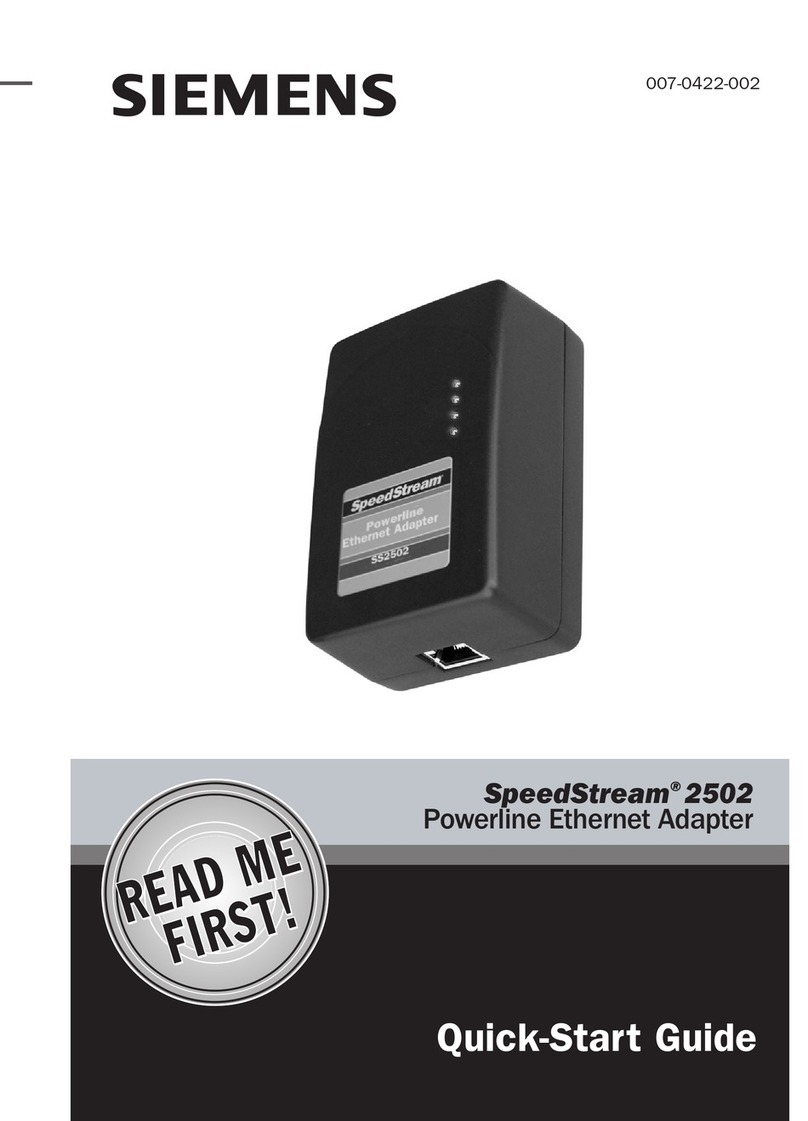
Siemens SpeedStream User manual

Siemens

Siemens SpeedStream User manual

Siemens DX791 User manual

Siemens

Siemens DX791 User manual

Siemens 8US1211-4TR00 User manual

Siemens

Siemens 8US1211-4TR00 User manual

Siemens Gigaset USB adapter 54 User manual

Siemens

Siemens Gigaset USB adapter 54 User manual

Siemens AEW36.2 User manual

Siemens

Siemens AEW36.2 User manual

Siemens AS-i F User manual

Siemens

Siemens AS-i F User manual

Siemens TCN2 User manual

Siemens

Siemens TCN2 User manual

Siemens XLS-MSE3-ADPT User manual

Siemens

Siemens XLS-MSE3-ADPT User manual

Siemens Gigaset 300 User manual

Siemens

Siemens Gigaset 300 User manual

Siemens 3VM9187-0SH20 User manual

Siemens

Siemens 3VM9187-0SH20 User manual

Siemens SIMATIC ET 200SP User manual

Siemens

Siemens SIMATIC ET 200SP User manual

Siemens Gigaset 108 User manual

Siemens

Siemens Gigaset 108 User manual

Siemens 8US1211-1NS10 User manual

Siemens

Siemens 8US1211-1NS10 User manual

Siemens SIRIUS 8WD4428-0BF User manual

Siemens

Siemens SIRIUS 8WD4428-0BF User manual

Siemens PC5777 User manual

Siemens

Siemens PC5777 User manual

Siemens 7XV5450 0BA00 User manual

Siemens

Siemens 7XV5450 0BA00 User manual

Siemens SITRANS AW200 User manual

Siemens

Siemens SITRANS AW200 User manual

Siemens SIMOGEAR BA 2039 User manual

Siemens

Siemens SIMOGEAR BA 2039 User manual

Siemens Gigaset 108 User manual

Siemens

Siemens Gigaset 108 User manual

Siemens FDB299 User manual

Siemens

Siemens FDB299 User manual

Siemens Gigaset Powerline Adapter 200 User manual

Siemens

Siemens Gigaset Powerline Adapter 200 User manual

Popular Adapter manuals by other brands

NetComm V220 Specifications

NetComm

NetComm V220 Specifications

NEC N8104-224 user guide

NEC

NEC N8104-224 user guide

Bosch GAA12V-21 Original instructions

Bosch

Bosch GAA12V-21 Original instructions

Superlux E901i quick start guide

Superlux

Superlux E901i quick start guide

NexusLink GPL-1200-KIT user manual

NexusLink

NexusLink GPL-1200-KIT user manual

Abocom WU5508 user manual

Abocom

Abocom WU5508 user manual

Manhattan 179195 user manual

Manhattan

Manhattan 179195 user manual

TRENDnet TPL-405E Quick installation guide

TRENDnet

TRENDnet TPL-405E Quick installation guide

Kramer ADC-DPM/HF user manual

Kramer

Kramer ADC-DPM/HF user manual

Leuze electronic CA-SET instructions

Leuze electronic

Leuze electronic CA-SET instructions

Mellanox Technologies ConnectX-3 Pro user manual

Mellanox Technologies

Mellanox Technologies ConnectX-3 Pro user manual

Philips CPWUA054/00 quick start guide

Philips

Philips CPWUA054/00 quick start guide

D-Link PowerLine DHP-500AV Quick installation guide

D-Link

D-Link PowerLine DHP-500AV Quick installation guide

Vivo MOUNT-AD4X2 instruction manual

Vivo

Vivo MOUNT-AD4X2 instruction manual

TP-Link Archer TX50UH user guide

TP-Link

TP-Link Archer TX50UH user guide

Atlantis A02-PL303-WN user manual

Atlantis

Atlantis A02-PL303-WN user manual

UEi CA383B instruction manual

UEi

UEi CA383B instruction manual

Endura A-CA74E instruction manual

Endura

Endura A-CA74E instruction manual

manuals.online logo
manuals.online logoBrands
  • About & Mission
  • Contact us
  • Privacy Policy
  • Terms and Conditions

Copyright 2025 Manuals.Online. All Rights Reserved.