Siemens VersiCharge SG VCSG30GRYUW User manual

1 ©2015 Siemens Industry, Inc. R814365 Rev05
Installation and Operations Manual
Siemens VersiCharge SG™

2 ©2015 Siemens Industry, Inc. R814365 Rev05
Contact Information
Siemens Industry, Inc.
Energy Management Division
Low Voltage and Products
5400 Triangle Parkway
Norcross, GA 30092
1-800-241-4453
www.usa.siemens.com/versicharge
FCC Compliance
This equipment has been tested and found to comply with the limits for a Class B digital device,
pursuant to part 15 of the FCC Rules. These limits are designed to provide reasonable protection
against harmful interference in a residential installation. This equipment generates, uses and can
radiate radio frequency energy and, if not installed and used in accordance with the instructions,
may cause harmful interference to radio communications. However, there is no guarantee that
interference will not occur in a particular installation. If this equipment does cause harmful
interference to radio or television reception, which can be determined by turning the equipment
off and on, the user is encouraged to try to correct the interference by one or more of the
following measures:
Reorient or relocate the receiving antenna.
Increase the separation between the equipment and the receiver.
Connect the equipment into an outlet on a circuit different from that to which the receiver
is connected.
Consult the dealer or an experienced radio/TV technician for help.
Changes or modifications not expressly approved by the party responsible for compliance may
void the user’s authority to operate the equipment and the warranty on the product.
Other Information
Product information is subject to change without notice. All trademarks are recognized as the
property of their respective owners.
For Siemens VersiCharge™ Warranty Terms and Conditions, see the Appendix on page 40 of
this manual.
© 2015 Siemens Industry, Inc. All rights reserved.

3 ©2015 Siemens Industry, Inc. R814365 Rev05
Table of Contents
1 Important Safety Information......................................................................................................5
1.1 Read this First.....................................................................................................................5
1.2 Symbol Legend ...................................................................................................................5
1.3 Product Labels ....................................................................................................................5
1.4 Definitions............................................................................................................................6
1.5 Safety Instructions (General and Specific)..........................................................................6
1.6 Instructions Pertaining to a Risk of Fire or Electric Shock...................................................7
1.7 Code and Standard References..........................................................................................7
2: Device Layout...........................................................................................................................9
2.1 Exterior – Front....................................................................................................................9
2.2 Exterior – LED Indicators ....................................................................................................9
2.3 Mounting Bracket (Receptacle not Included) ....................................................................10
2.4 Exterior – Rear..................................................................................................................11
2.5 Interior – Connection Area ................................................................................................12
2.6 Device States....................................................................................................................13
Section 3: Installation..................................................................................................................14
3.1 Building Survey .................................................................................................................14
3.2 Site Selection ....................................................................................................................14
3.3 Cord-and-plug installation .................................................................................................15
3.4 Hard-wired installation.......................................................................................................17
3.5 Amperage Adjustment.......................................................................................................18
3.6 Remote Control Interface..................................................................................................19
3.7 Smartphone, Tablet , and Cloud App Setup......................................................................20
Section 4: Operation...................................................................................................................25
4.1 Overview ...........................................................................................................................25
4.2 Typical Operation..............................................................................................................25
4.3 Faults.................................................................................................................................25
4.4 Cord Management.............................................................................................................26
4.5 Delay Timer.......................................................................................................................26
4.6 Halo Operation..................................................................................................................27
4.7 Remote Control Interface..................................................................................................28
4.8 App Operation...................................................................................................................28
Section 5: Troubleshooting.........................................................................................................37
5.1 General Settings................................................................................................................37
5.2 Specific Errors and Actions...............................................................................................37

4 ©2015 Siemens Industry, Inc. R814365 Rev05
Section 6: Warranty ....................................................................................................................38
Section 7: Wiring Diagrams ........................................................................................................41

5 ©2015 Siemens Industry, Inc. R814365 Rev05
1 Important Safety Information
1.1 Read this First
This manual contains important instructions for use during installation, operation and
maintenance of the Siemens VersiCharge™ SG electric vehicle charging station.
1.2 Symbol Legend
To reduce the risk of electrical shock, and to ensure the safe installation and operation of the
Siemens VersiCharge™ SG, the following safety symbols appear throughout this document to
indicate dangerous conditions and important safety instructions.
DANGER Hazardous voltage. Will cause death or serious injury. Turn off Power before
working on this equipment. This indicates a situation where the present voltage could
cause injury or death. Extreme caution is required when servicing or installing the
equipment referenced.
DANGER
Explosion hazard. This equipment has arcing or sparking parts that should not
be exposed to flammable vapors. Use extreme caution and follow instructions carefully.
WARNING! This indicates a situation where failure to follow instructions may be a safety
hazard or cause equipment malfunction. Use extreme caution and follow instructions
carefully.
NOTE: This indicates information particularly important for optimal system operation.
Follow instructions closely.
Indicates connection point for Ground conductor.
1.3 Product Labels
The following symbols appear on the product label and are described here:
This label indicates the risk of hazardous
voltage and electric shock which will cause
death, serious injury, or substantial damage.
Turn off power supplying this device before
working inside.
DANGER
Explosion hazard. This equipment has arcing or sparking parts that should not
be exposed to flammable vapors. Use extreme caution and follow instructions carefully.

6 ©2015 Siemens Industry, Inc. R814365 Rev05
Indicates connection point for Ground conductor.
1.4 Definitions
The term EV used in this manual refers to an electric vehicle.
The term AC used in this manual refers to alternating current.
The term ‘VersiCharge SG’ unit refers to any Wi-Fi enabled VersiCharge SmartGrid unit with a plug and
cord assembly attached, i.e. part numbers VCSG30GXXXX (Indoor / Outdoor Use).
The SmartGrid (SG) term in this product description refers to the capability of this unit to respond to
demand response events and operate on a schedule synched with the power company’s capacity
constraints. The owner of a VersiCharge SG unit can cancel or opt out of any utility event as long as this
is not defined differently in the specifications of the utility program. The user should be aware of any
increase in cost or disqualification from the utility programs specified by the utility as a result of canceling
or opting out events.
The Siemens VersiCharge line of EV Charging Systems includes a Charging Circuit Interrupting
Device (CCID). The CCID is required by UL Standard 2231 and is designed to detect grounding faults
within the system, and disconnect power from the downstream conductors when a fault is detected.
Arcing component in contactor: Siemens VersiCharge EV Charging Systems include a contactor that,
when opened or closed, will cause a short duration arc. The contactor is enclosed in an appropriate
electrical enclosure, but use caution in the presence of flammable vapors. The vapors could ignite,
creating an explosion. Store flammable vapors away from all electrical equipment, and should vapors be
present, allow sufficient time for ventilation before operating this equipment.
1.5 Safety Instructions (General and Specific)
DANGER Hazardous voltage. Will cause death or serious injury. Turn off power supplying this
equipment before working inside
- Read this Installation and Operations Manual in its entirety prior to installing, maintaining,
servicing or replacing a Siemens VersiCharge EV Charging System.
- Permits: Be aware that many areas require special permits and/or utility approvals to install EV
charging equipment. Contact your local electrical inspector’s office and your local utility prior to
beginning work to understand local requirements.
- Qualified person: Because of the inherent dangers of electricity, only a qualified person should
install, maintain, service, or replace electrical wiring and connected equipment. For the purpose
of this manual, a qualified person is one who is familiar with the installation, construction of
operation of the equipment and the hazards involved. In addition, this person should meet the
definition of a qualified person pursuant to the National Electrical Code® (NEC®)1. Failure to
comply with the recommendation of having a qualified person install the unit when electrical
work is required may void the warranty provided with this device.
- Weatherproof seals: VersiCharge SG units may be used indoors and outdoors.
WARNING! Failure to properly seat seals can result in water, debris and other foreign objects
entering into the device. These can cause damage to electrical components and prevent the
device from functioning properly.
1National Electrical Code and NEC are Registered Trademarks of the National Fire Protection Association (NFPA)

7 ©2015 Siemens Industry, Inc. R814365 Rev05
1.6 Instructions Pertaining to a Risk of Fire or Electric Shock
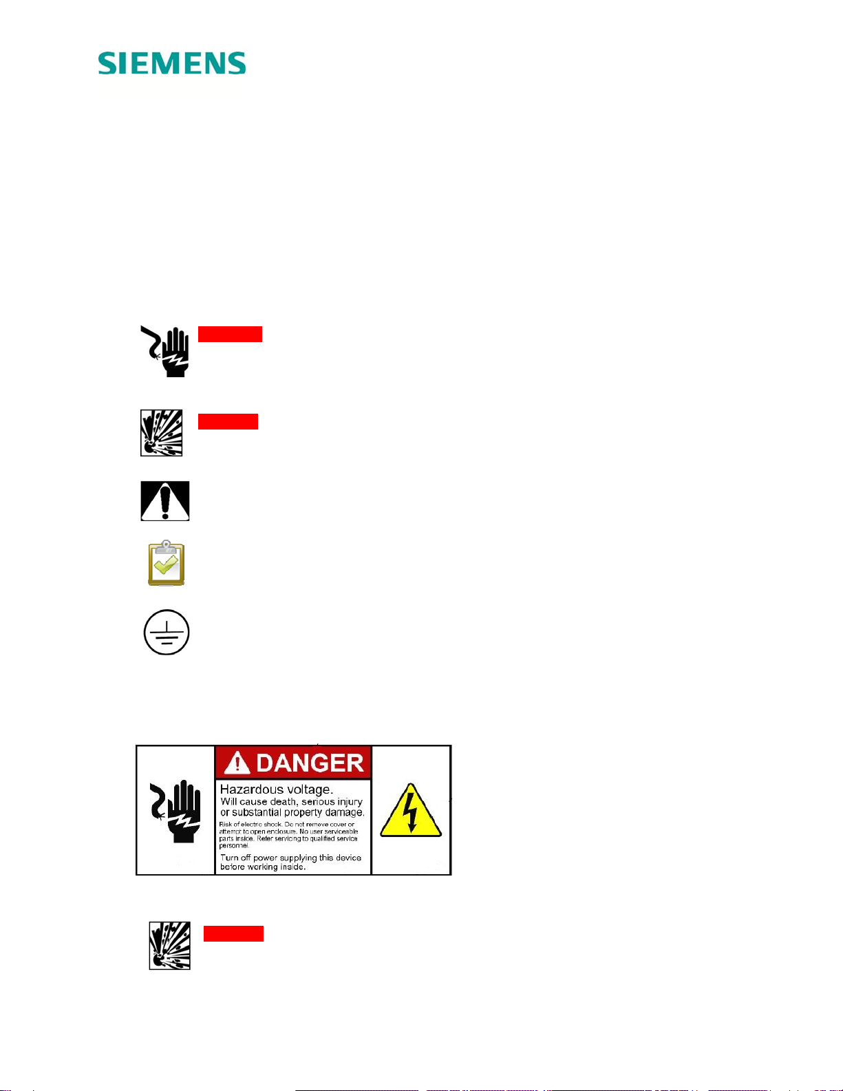
WARNING! When using electric products, basic precautions should always be followed,
including the following. This manual contains important instructions for the Universal Unit that
shall be followed during installation, operation and maintenance of the unit:
- Read all of the instructions before using this product.
- Failure to follow these instructions may lead to death, serious injury or property damage.
- Any electrical wiring required to install this device shall conform to applicable codes and
standards (ANSI/NFPA 70). A qualified electrician is recommended to perform these
tasks.
- To reduce the risk of electric shock, never service, install or uninstall this device from
service while energized.
- This equipment has arcing or sparking parts that should not be exposed to flammable
vapors. This equipment should be located at least 18 inches above the floor.
- This device is equipped with an auto reset feature
oIf this device is connected to a vehicle at the time that power is restored following an
outage, charging may automatically resume.
oIf this device is connected to a vehicle and a ground fault trip occurs, charging may
automatically resume after a delay period.
- This device should be supervised when used around children.
- Do not put fingers into the electric vehicle coupler.
- Do not use this product if the flexible power cord or EV cable is frayed has broken
insulation, or any other signs of damage.
- Do not use this product if the enclosure or the EV coupler is broken, cracked, open, or
shows any other indication of damage.
- A torque driver shall be used to make power connections to ensure that adequate contact
pressure is applied. See the installation section of this manual for additional details.
- A device provided with a wire connector for field installed wiring shall be provided with
instructions specifying that the connector provided shall be used in making the field
connection.
- When installing this device in the hard wired configuration, power connections shall be
made at line terminals with 14.5 lb-in torque.
- An insulated grounding conductor that is identical in size, insulation material, and
thickness to the grounded and ungrounded branch-circuit supply conductors, except that
it is green with or without one or more yellow stripes, shall be installed as part of the
branch circuit that supplies the device or system.
- The grounding conductor shall be grounded to earth at the service equipment or, when
supplied by a separately derived system, at the supply transformer.
- Do not attempt to operate this device if the ambient temperature is greater than
50C(122F)
- Use 6-8 AWG, 75°C copper wire to connect to supply circuit.
- CAUTION: To reduce the risk of fire, connect only to a circuit provided with 40 amperes
maximum branch circuit over current protection in accordance with the ANSI/NFPA 70
National Electrical Code.
1.7 Code and Standard References
- This device has been designated to meet the requirements in section 626 of the National
Electric Code (NEC®).
- UL Listing with Listing Number – Siemens VersiCharge Devices are listed in UL file #
E348556
- Complies with the following UL Standards: 2594, 2231-1, 2231-2
- EV interface compliant to SAE J-1772 Level II

8 ©2015 Siemens Industry, Inc. R814365 Rev05
- This equipment has been tested and found to comply with the limits for a Class B digital
device, pursuant to part 15 of the FCC Rules.
- Personal Protection Equipment: Use of proper personal protection equipment, including,
but not limited to, eye protection, shock protection, gloves and other appropriate
protection, is recommended when installing or servicing any electrical equipment
DANGER Explosion hazard. This equipment has arcing or sparking parts that should
not be exposed to flammable vapors. This equipment should be installed at least 18
inches above floor or ground level. Use extreme caution and follow instructions
carefully.

9 ©2015 Siemens Industry, Inc. R814365 Rev05
2: Device Layout
2.1 Exterior – Front
1. Pause Button
2. Delay Timer Button
3. Coupler
4. Coupler Holster
5. Halo Indicator
6. Enclosure Screws
7. Hinges
2.2 Exterior – LED Indicators
1. Power Available
2. Pause
3. Charging
4. Service Portal
5. Wi-Fi Status
6. Time Delay
7. Ready
8. Fault
9. Remote Control
10. Remote Control Lock
11. Time Delay Duration (hrs.)
2
1
3
4
5
6
7
21 3
78
6
11
4
10
9
5

10 ©2015 Siemens Industry, Inc. R814365 Rev05
2.3 Mounting Bracket (Receptacle not Included)
1. Mounting Holes
2. Receptacle cutout
3. Mounting Slot
4. Mounting Tab
1
3
2
4

11 ©2015 Siemens Industry, Inc. R814365 Rev05
2.4 Exterior – Rear
1. Mounting Tabs
2. Plug and cord assembly in fed from behind wiring option
3. Fed from the bottom wiring option
4. Coupler and cord assembly
3
2
1
4

12 ©2015 Siemens Industry, Inc. R814365 Rev05
2.5 Interior – Connection Area
1. Line Conductor Connections
2. Ground Connection
3. Remote Control Interface
4. Wi-Fi Module and CEA2045 Connector
1
2
3
4

13 ©2015 Siemens Industry, Inc. R814365 Rev05
2.6 Device States
EVSE's do not have the capability to determine whether your car has been charged or not. Refer to car
manual for indication of car battery status.
State Name Description Indicator(s) Halo Status
Indicator
Power Available 240V or 208V Power Present 'Power Available' Off
Ready to
Charge EV detected, waiting for charging
command from EV 'Power Available' and
‘Ready’ Green - Solid
Charging Charging EV 'Power Available' and
'Charging' Green - Fading in
and out
Pause* Operation paused 'Power Available’ and
‘Pause’ Off
Delay Timer Operation awaiting delay timer 'Power Available' and
'Hour(s) Delay' Off
Remote - Third
Party System is controlled via third
party remote control interface 'Power Available' and
‘Remote Control Lock' ** Dependent upon
command
Remote - Local Last command received initiated
via application ‘Power Available’ and
‘Remote Control’ Dependent upon
command
Reduced
Charge Commanded to limit the
maximum available rate to less
than 7.2kW maximum
‘Power Available’ on and
‘Charging’ pulsing** Green - Fading in
and out
* Some EV’s may initiate a delay of charge when exiting out of the ‘Pause’ state before the EV starts
telling the VersiCharge to start charging again. Please refer to the user manual for the EV for further
information.
** Press and hold the “Pause” button for 5 seconds to opt out of a remote third party (demand response)
event or to return charge rate to maximum kilowatt charge. Please be aware that consistently opting out
of DR events may disqualify some utility rate programs.
Further combinations of indicators on the unit are described in the Fault code section 4.3.

14 ©2015 Siemens Industry, Inc. R814365 Rev05
Section 3: Installation
3.1 Building Survey
Available voltage, current and frequency:
VersiCharge EV charging stations can draw up to 30A at 240 VAC, 50/60 Hz (7.2kW of
power). The complete electrical structure of the building must be adequately sized to
handle the entire building energy load, under peak conditions, as well as the charging
station load under operation.
Checking for adequate power includes all the connections from the utility through the
entire circuit structure to the branch circuit position and connected wiring.
Utility connection and transformer capacity - check with utility service provider to ensure
enough power is available for the building and the VersiCharge under full loading.
Available breaker positions and amperage
Verify the panel has an open position for a two pole breaker.
Verify that the additional 30 A draw from the VersiCharge will not exceed the total loading
for the Main Breaker of the structure.
Breaker selection
A 2-pole 40 A dedicated branch circuit breaker is required for both cord-and-plug
installation and hard wired installations. Siemens Part numbers: Q240 (plug-in type),
B240 (bolt-on type).
The VersiCharge must be wired on a dedicated circuit, with no other loads wired on that
circuit.
3.2 Site Selection
NOTE: To ensure optimal functionality, we do not recommend installing the VersiCharge
unit in the direct sunlight.
Accessibility
When selecting a mounting site, ensure that the coupler can reach the EV before starting
installation.
The VersiCharge will mount on the surface of the wall, protruding at least 18 inches, and
a location for installation should be chosen where there is sufficient space to park an EV,
walk past the device, open nearby doors, etc., without obstruction.
If the installation location is not already wired for installation, installation of the
VersiCharge unit should be planned with an electrician and then the electrician should
bring in the electricity according to those guidelines.

15 ©2015 Siemens Industry, Inc. R814365 Rev05
DANGER Explosion hazard. This equipment has arcing or sparking parts that should not
be exposed to flammable vapors. This equipment should be installed at least 18 inches
above floor or ground level. Use extreme caution and follow instructions carefully.
3.3 Cord-and-plug installation
The standard VersiCharge SG unit arrives factory-configured for rear fed and bottom fed
cord-and-plug installations. For hardwired installations, please refer to section 3.4 of this
manual. Please note that once the cord is removed, it shall not be reinstalled on the unit,
otherwise the warranty will be voided.
WARNING! Due to risk of moisture, cord-and-plug installations require a NEMA outdoor
rated receptacle and enclosure, when installed outdoors. Installing outdoors without
properly rated outdoor receptacles and enclosures will violate listings and void the device
warranty. Outdoor cord-and-plug installations must be bottom fed only.
Bottom-fed, Cord-and-Plug Installation
Measure the plug in cord of the unit first since the mounting bracket and the receptacle
need to be located within this distance of each other.
Locate a stud within the wall to attach
the mounting bracket.
oFor concrete or masonry walls,
install appropriate anchors.
oVerify that the stud or anchor and
surrounding materials can handle the
20+ lbs load of the VersiCharge.
Receptacle will be located below
VersiCharge mounting bracket, either to
the left or the right of the stud to which
the mounting bracket will be attached.
Verify receptacle location complies with
local code requirements.
oNEC® 2014 specifies: Indoor (NEC®
Article 625.29B) installation 18 – 48
inches above ground level.
oVerify local code with respect to
installation height.
Wire a standard NEMA 6-50 receptacle
using appropriate wire.
Using 7/16 inch socket head and drill, attach the mounting bracket to the wall using two
lag screws provided. Verify that lag screws are going into the stud.

16 ©2015 Siemens Industry, Inc. R814365 Rev05
Hang the VersiCharge on the Mounting Bracket
by first hooking the bottom of the unit into the
mounting slot and then hooking the top into the
mounting tab.
Secure VersiCharge to wall and mounting
bracket using provided screws.
Ensure that the breaker for the circuit on which
the receptacle is wired is turned to the ‘OFF’
position, plug the VersiCharge into the receptacle
and switch the breaker to the ‘ON’ position.
Rear-fed, Cord-and-Plug Installation
NOTE: Flush mount installations only,
meaning the receptacle is even with wall in
which it is installed.
Locate a stud within the wall to attach the
mounting bracket.
oFor concrete or masonry walls, install
appropriate anchors.
oVerify that the stud or anchor and
surrounding materials can handle the
20+ lbs load of the VersiCharge.
Ensure that receptacle can be flush mount
installed to the left side of the mounting
bracket.
oReceptacle should be installed prior to
mounting the VersiCharge to the wall.
oNEC® 2014 specifies: Indoor (NEC®
Article 625.29B) states installation 18 –
48 inches above ground level.
oVerify local code with respect to
installation height.
Wire a standard NEMA 6-50 receptacle
using appropriate wire.

17 ©2015 Siemens Industry, Inc. R814365 Rev05
Using 7/16 inch socket head and drill, attach the Mounting Bracket to the wall using two
lag screws provided. Verify that lag screws are going into the stud.
Before starting the step to hang the
VersiCharge unit onto the mounting bracket,
ensure that the circuit breaker on the circuit for
the receptacle is turned to the ‘OFF’ position.
To hang the unit onto the mounting bracket,
place bottom mounting tab into corresponding
slot in mounting bracket. Plug cord into
receptacle. Rotate the unit towards the wall so
that the hook on the unit goes over the top
mounting bracket. Turn the breaker for this
circuit back to the ‘ON’ position to power up
the VersiCharge.
Secure VersiCharge to wall and mounting
bracket with provided screws
3.4 Hard-wired installation
This section describes the hard-wired installation and the removal of the cord and plug
assembly in case the VersiCharge SG units need to be hard-wired during installation.
Removing the Cord-and-Plug Assembly
DANGER Hazardous voltage. Will cause death or serious injury. Turn off power
before working on this equipment by turning the circuit breaker to which this
circuit is wired to the ‘OFF’ position.
Open hinged cover by loosening four cover
Phillips closure screws.
Remove barrier by removing the two securing
screws.
Remove the cord-and-plug assembly from the
conductor opening
oDisconnect the attachment plug wires from
the terminal block by loosening screws in
position 1, 2, and 3.
oDo not adjust the two screws on top of the
terminal block unit. These are for factory use only.
oDisconnect and remove strain relief and entire cord-and-plug
assembly

18 ©2015 Siemens Industry, Inc. R814365 Rev05
Route conductors, with proper strain relief, into the VersiCharge from the conductor
opening
oPull 3-6 inches of slack through the conductor opening
Place bottom mounting tab into corresponding slot in mounting bracket. Secure
VersiCharge to wall and mounting bracket
Wire conductors (copper only) into device (L1, L2 and Ground) from connected conduit.
Using torque screw driver, torque all lugs to 14.5 lb-in.
Replace barrier and secure with the two screws which were removed in the beginning.
Rotate the unit towards the wall so that the hook on the unit goes over the top mounting
bracket.
Replace hinged cover, securing with four Phillips head screws
Turn the circuit breaker for the this circuit to the ‘ON’ position
Secure VersiCharge to wall and mounting bracket
3.5 Amperage Adjustment
The Siemens VersiCharge has the option to set the maximum amperage/power that the
car may draw using the Amperage adjustment dial. Note that Versicharge cannot control
the power draw to the EV, it can only communicate the current capacity of the device to
the EV.
NOTE: The EV controls the power draw. the VersiCharge only communicates the
maximum available power to EV.
Dial Settings
Amperage adjustment dial is for use by a qualified technician only
Purpose of the amperage adjustment dial is to set the max current that the EV is allowed
to draw from the charging station.
The dial has 10 settings
o0-4 are for amperage adjustments
oSettings 5-9 are for factory use only. These settings will result in a fault if used.
Verify that the VersiCharge is disconnected from power when changing the amperage
adjustment dial
For a more thorough explanation of how this setting is displayed in the VersiCharge SG
mobile and web application, please refer to section 4.8 of this manual

19 ©2015 Siemens Industry, Inc. R814365 Rev05
Circuit Requirements
Circuit must be sized for the max ampere requirement. Do not de-rate breakers or
conductors based on amperage adjustment
3.6 Remote Control Interface
The Siemens VersiCharge has a Remote Control Interface that allows charging to be
controlled by an external device. This function is for wired control, and is separate from
the remote control system associated with phone and web applications.
WARNING! Remote Control Interface should be low voltage control wiring. Installing
higher voltage on this interface can cause damage to unit, preventing it from functioning
properly. Do not hook up 120/240 V to these connections.
Control Switch input is a dry contact input from
an external source.
Status Output indicates the charging status of
the VersiCharge.
The Remote Control Interface is located inside
the unit so to connect a device, the unit has to
be opened by taking the following steps:
oSet the circuit breaker for this circuit to the
‘OFF’ position
Setting 0 1 2 3 4
Label MIN 25% 50% 75% MAX
Current (A) 6 7.5 15 22.5 30
Power (kW) 1.44 1.8 3.6 5.4. 7.2

20 ©2015 Siemens Industry, Inc. R814365 Rev05
oOpen hinged cover by loosening four cover Phillips closure screws.
oRemove barrier by removing the two securing screws.
oRemove connector to run wire
oRoute control wiring, with proper protection and strain relief, through the low voltage
wire opening. Do not route the wiring along with any high voltage connections
oInstall external control source according to the instructions provided with that device
oTurn the circuit breaker for this circuit back to the ‘ON’ position to power your
VersiCharge back up
Note: See section 4.7 for more details on this interface
3.7 Smartphone, Tablet , and Cloud App Setup
The ability to control and monitor the VersiCharge SG is what seperates this product from
previous generations of the Siemens VersiCharge as well as competitors. There are
three different modes of communicating with the VersiCharge SG:
1) Smartphone Application: This is the preferred method for most SG owners. Search
for “VersiChargeSG” in the App Store for the iOS operating system (for iPhone
owner) or in the Google Play Store for the Android operating system. Please
download this free smartphone application.
2) Cloud Application: Using your preferred browser you may control and monitor your
VersiCharge SG by entering the following URL: https://versichargesg.cloudapp.net.
This is suggested to be the secondary or backup mode of interfacing with the
VersiCharge SG.
3) Local Web Pages: Using your web enabled device connect to the VersiCharge SG
access point (identifiable with prefix “vs”- traceability number). Enter
http://local.versichargesg.net in a new window of your preferred web browser. This
will navigate you to the local web pages of the SG (identical functionality as web
app). Most users only employ this mode of communication in the case of a Wi-Fi
network failure or outage.
NOTE: In case of a Wi-Fi network failure, the charger will continue to function based
upon last registered state. If the schedule function is enabled, it will continue to run
indefinitely. All demand response settings will be saved. Faceplate functionality will
remain the same.
User Registration Process
Open the Smartphone app from your phone or the cloud application from
your computer/tablet/phone at https://versichargesg.cloudapp.net
(ensure you have an internet connection on your device). In this manual
the registration process is shown by example of the phone app. The web
app user registration process follows the same steps.
Table of contents
Other Siemens Automobile Accessories manuals

Siemens
Siemens HKW-600 User manual

Siemens
Siemens VersiCharge User manual

Siemens
Siemens VersiCharge Ultra 175 User manual

Siemens
Siemens SICHARGE D 8EM5907-0AA000-1AA7.05 User manual

Siemens
Siemens VersiCharge AC Instruction Manual

Siemens
Siemens VersiCharge AC User manual

Siemens
Siemens VersiCharge Ultra 175 User manual

Siemens
Siemens HKW-700 User manual

Siemens
Siemens SICHARGE D 8EM5907-0AA00-1AA7.01 User manual

Siemens
Siemens 8EM1310-2EH04-0GA0 Administrator guide