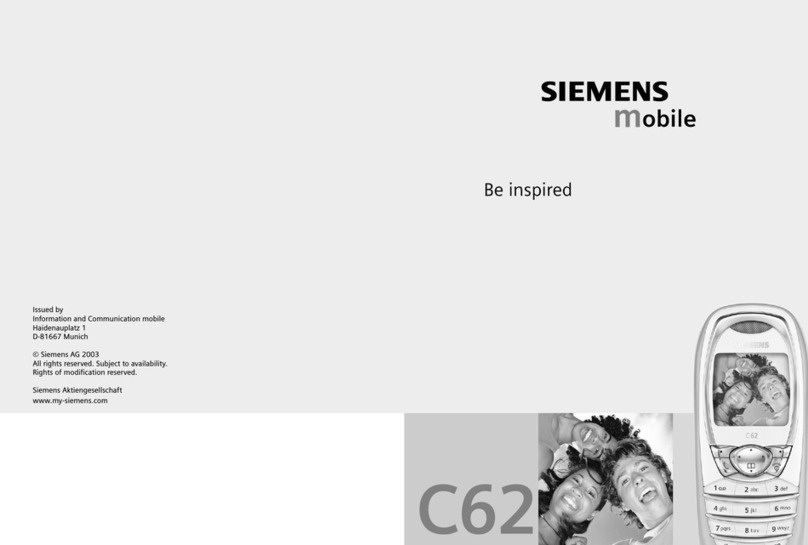
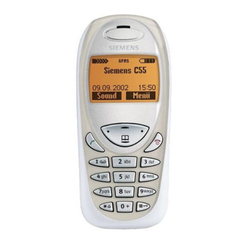
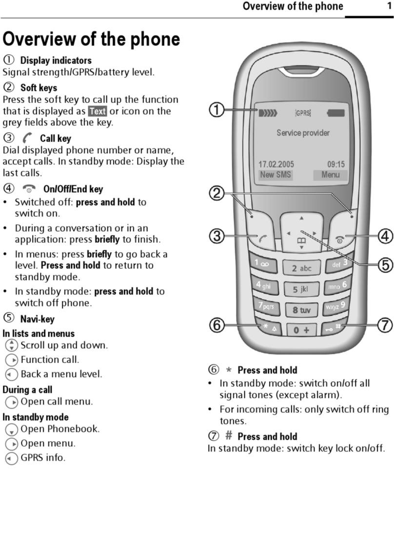
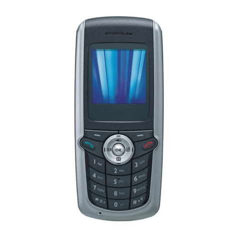
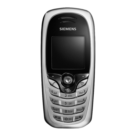
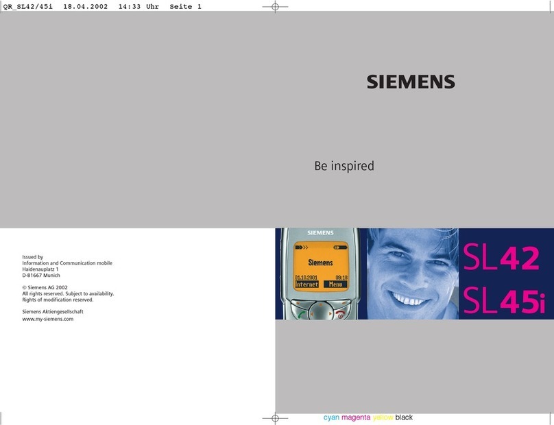
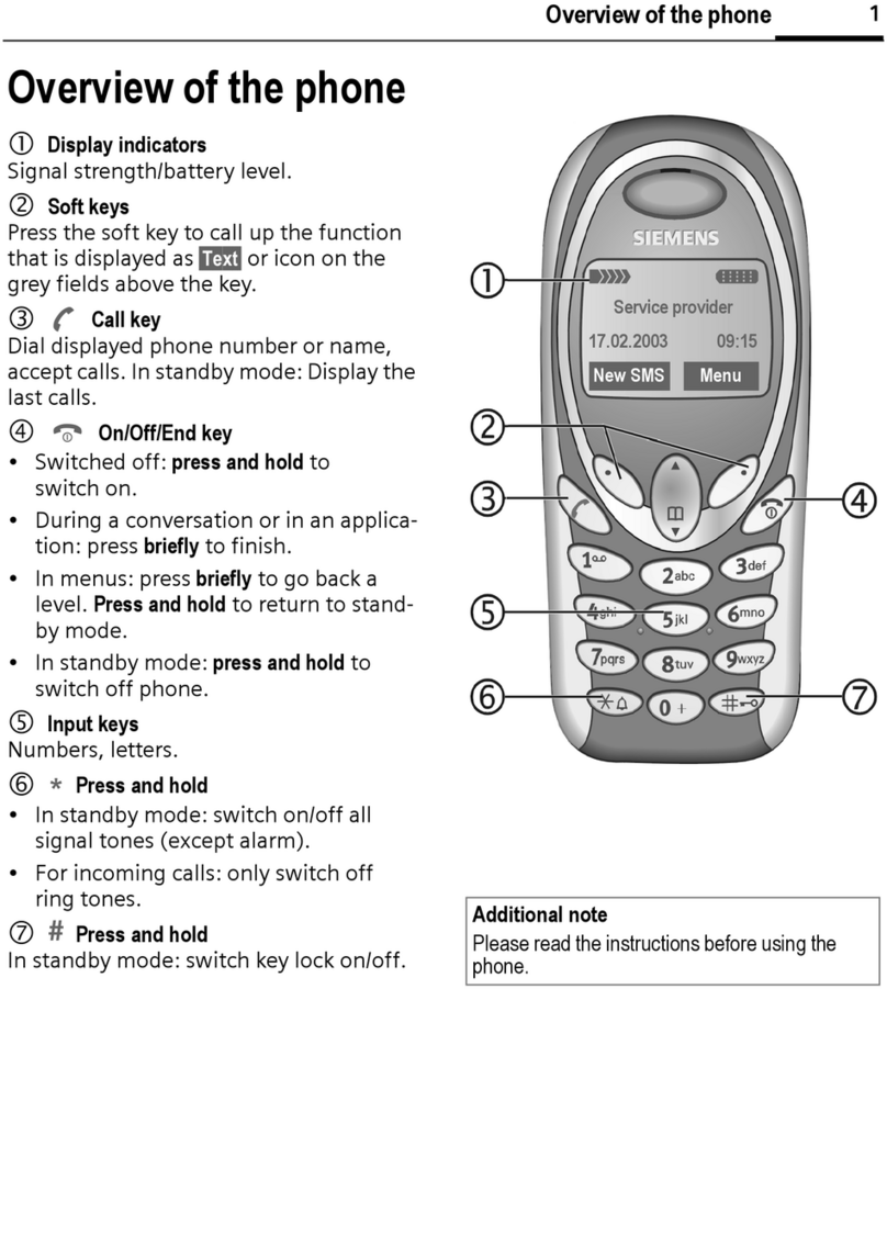
Siemens C62 User manual

Local Service Organization Service Manual
BE INSPIRED
C
C
C6
6
62
2
2
SIEMENS COMMUNICATIONS UNLIMITED
Our innovation shapes the future

SIEMENS PTE LTD
C62 Level 2 Service Manual
Copyright © Siemens Pte Ltd. C62 Level 2 manual V1.1
All Rights Reserved
ICM MP CCQ SLI RHQ 1 of 47 Internal Use Only
Table of Contents
1 GPRS (GERENAL PACKET RADIO SERVICE)....................................................2
2 KEY FEATURES......................................................................................................3
3 ACCESSORIES ……………………………………………………………………….6
4 UNIT DESCRIPTION C62.. …………………..……………………….………….…..8
4.1 Exploded View of C62……………………………………………………………………...9
4.2 Parts List…………………………………………………………………………………...10
5 DISASSEMBLY OF C62......………………………………………………………...11
6 REASSEMBLY OF C62..…………………………………………………………….16
7 MOBILE SOFTWARE PROGRAMMING…………………………………………..21
8 SIEMENS SERVICE EQUIPMENT USER MANUAL……………………………..32
9 JPICS, JAVA BASED PRODUCT INFORMATION CONTROLLER…………....33
10 INTERNATIONAL MOBILE EQUIPMENT IDENTITY, IMEI..…………………….39
11 GENERAL TESTING INFORMATION………………………….…………………..40
Annex 1………………………………………………………………………………..45
Annex 2………………………………………………………………………………..46

SIEMENS PTE LTD
C62 Level 2 Service Manual
Copyright © Siemens Pte Ltd. C62 Level 2 manual V1.1
All Rights Reserved
ICM MP CCQ SLI RHQ 2 of 47 Internal Use Only
1GPRS (GENERAL PACKET RADIO SERVICE)
GPRS is a new non-voice value added services that allows information to be sent and received
across a GSM mobile telephone network. It supplements today’s Circuit Switched Data (CSD)
and Short Message Services (SMS). GPRS involves overlaying a packet based air interface on
the existing circuit switched GSM network. This gives the option to use a packet-based data
service. The information is split into separated but related “packets” before being transmitted and
reassembled at the receiving end. Theoretically, maximum speeds of up to 171.2 kilobits per
second (kbps) are achievable with GPRS using all eight timeslots at the same time. This is about
3 times as fast as the data transmission speed possible over today’s fixed telecommunications
networks and 10 times as fast as current Circuit Switched Data services on GSM networks.
Figure1. Example of GPRS data transmission
Example: Cell with 1 Frequency channel:
1 physical channel for signaling, 4 physical channels for Circuit switched and 3 physical channels
for Packet switched.

SIEMENS PTE LTD
C62 Level 2 Service Manual
Copyright © Siemens Pte Ltd. C62 Level 2 manual V1.1
All Rights Reserved
ICM MP CCQ SLI RHQ 3 of 47 Internal Use Only
2 Key Features
Frequency Bands • GSM Phase 2+, triple-band - EGSM 900 / GSM 1800 /
GSM 1900, GPRS
Power • EGSM 900 : Power Class 4
• GSM 1800 : Power Class 1
• GSM 1900 : Power Class 1
Battery • Li-ion Battery Pack
• Operational Voltage : 3.4 ~ 4.2 V
• Nominal Capacity : 630 mAh
Stand-by Time • Min 60 Hrs
• Max 250 Hrs
(actual time depends on the network)
Talk Time • Best case : min 1.5 hours
• Best case : max 4.5 hours
(Actual time depends on the network)
Charging Time • 3.5 hrs for a full battery
SIM Card • Plug In card 1.8 or 3V
• SIM application Tool Kit
Message • SMS – MT, MO, CB. Predictive Text Input & T9
• EMS
• MMS Support
Display • LCD: 128 x 128 pixels, 4k colours, 7 lines
Physical Details • Dimension: 101 mm (L) x 44 mm (W) x 20 mm (H)
• Volume: ~ 72 cc
• Weight: ~ 75 g

SIEMENS PTE LTD
C62 Level 2 Service Manual
Copyright © Siemens Pte Ltd. C62 Level 2 manual V1.1
All Rights Reserved
ICM MP CCQ SLI RHQ 4 of 47 Internal Use Only
Keypad • Power / End key and Send key
• 2 soft keys and 4-way menu keys
• 12 numeric keys (10 numeric, # and 8)
Key Sound • Click / Tone / Silent
Key Lock • Activation by pressing and holding #-key or Automatic
• Deactivation by pressing and holding #-key
Antenna • Integrated
Dialling • Last 10 dialled calls
• Last 10 received calls with date/time stamp
• Last 10 missed calls with date /time stamp
Ringer • On/Off/Beep
• 16 Polyphonic melodies
• User defined melodies (this is limited to the availability of the
memory space in the phone.)
Speech Codec • FR, EFR, HR
Speaker Volume • Adjustable in 6 levels during call via softkey or Up-menu key.
Silent Alert • Built-in vibrator
Phone Book • Up to 500 entries
Supplementary
Services
• AOCC (Advice of Charge Charging)
• AOCI (Advice of Charge Information)
• CAI (Display of Charge Advice Information)
• CB (Call Barring)
• CF (Call Forwarding)
• CH (Call Hold)
• CLIP (Calling Line Identity Presentation)
• CLIR (Calling Line Identity Restriction)
• COLP (Connected Line Identity Presentation)
• COLR (Connected Line Identity Restriction)
• CPHS 4.2 (Common PCN Handset Specification)
• CT (Call Transfer)
• CW (Call Waiting)
• FDN (Fixed Dialing Numbers)

SIEMENS PTE LTD
C62 Level 2 Service Manual
Copyright © Siemens Pte Ltd. C62 Level 2 manual V1.1
All Rights Reserved
ICM MP CCQ SLI RHQ 5 of 47 Internal Use Only
• LND (Last Numbers Dialled List)
• MTPY (Multiparty Conference)
• SDN (Service Dialing Number)
• SMS MO (Mobile Originated)
• SMS MT (Mobile Terminated)
• USSDwork (Unstructured Supplementary Service Data)
Ciphering • GEA1
PIN Control • PIN 1, PIN 2
Network function • Automatic and manual network selection
Chipset • EMP Carbon
Imaging • Attachable QuickPic Camera with flash(VGA camera)

SIEMENS PTE LTD
C62 Level 2 Service Manual
Copyright © Siemens Pte Ltd. C62 Level 2 manual V1.1
All Rights Reserved
ICM MP CCQ SLI RHQ 6 of 47 Internal Use Only
3 Accessories
For the C62, the following accessories will be available.
Li-ion Battery EBA-610 Travel Charger ETC-500 (EURO)
Travel Charger ETC-510 (UK) Headset PPT HHS-510
QuickPic Camera Set IQP-500 Basic Car Pack HKB-500

SIEMENS PTE LTD
C62 Level 2 Service Manual
Copyright © Siemens Pte Ltd. C62 Level 2 manual V1.1
All Rights Reserved
ICM MP CCQ SLI RHQ 7 of 47 Internal Use Only
Car Charger ECC-500 Car Kit Portable HKP-500
Pictures are not available for the following accessories:
Travel Charger ETC-520 (U.S.A)
Data Cable DCA-500
Data Cable USB DCA-510

SIEMENS PTE LTD
C62 Level 2 Service Manual
Copyright © Siemens Pte Ltd. C62 Level 2 manual V1.1
All Rights Reserved
ICM MP CCQ SLI RHQ 8 of 47 Internal Use Only
4 Unit Description C62
Mechanically the C62 mobile phone is built up by plastic front and back covers, a plastic antenna
cover, a transceiver PWB and a battery case. Inner surface of the B-cover is covered with a metal
layer and a conducting gasket.
The housing of the phone is closed with 5 screws that keep the B-cover, the A-cover and all the
parts between those together.
See details for disassembly and assembly in the following chapters.
Length 101 mm
Width 44 mm
Thickness 20 mm
Weight 75 g

SIEMENS PTE LTD
C62 Level 2 Service Manual
Copyright © Siemens Pte Ltd. C62 Level 2 manual V1.1
All Rights Reserved
ICM MP CCQ SLI RHQ 9 of 47 Internal Use Only
4.1 Exploded View of C62

SIEMENS PTE LTD
C62 Level 2 Service Manual
Copyright © Siemens Pte Ltd. C62 Level 2 manual V1.1
All Rights Reserved
ICM MP CCQ SLI RHQ 10 of 47 Internal Use Only
4.2 Part List
Pos. Description Qty
1 A-cover assembly, Eagle White 1
1 A-cover assembly, Pigeon Blue 1
1 A-cover assembly, Cherry Red 1
2 LCD-module 1
3 KEYMAT ASSEMBLY HD0503 LATIN Eagle White 1
3 KEYMAT ASSEMBLY HD0503 CHINESE Eagle White 1
3 KEYMAT ASSEMBLY HD0503 HEBREW Eagle White 1
3 KEYMAT ASSEMBLY HD0503 CYRILLIC Eagle White 1
3 KEYMAT ASSEMBLY HD0503 THAI Eagle White 1
3 KEYMAT ASSEMBLY HD0503 BOPOMOFO Eagle White 1
3 KEYMAT ASSEMBLY HD0503 ARABIC Eagle White 1
3 KEYMAT ASSEMBLY HD0503 GREEK Eagle White 1
3 KEYMAT ASSEMBLY HD0503 LATIN Pigeon Blue 1
3 KEYMAT ASSEMBLY HD0503 CHINESE Pigeon Blue 1
3 KEYMAT ASSEMBLY HD0503 HEBREW Pigeon Blue 1
3 KEYMAT ASSEMBLY HD0503 CYRILLIC Pigeon Blue 1
3 KEYMAT ASSEMBLY HD0503 THAI Pigeon Blue 1
3 KEYMAT ASSEMBLY HD0503 BOPOMOFO Pigeon Blue 1
3 KEYMAT ASSEMBLY HD0503 ARABIC Pigeon Blue 1
3 KEYMAT ASSEMBLY HD0503 GREEK Pigeon Blue 1
3 KEYMAT ASSEMBLY HD0503 LATIN Cherry Red 1
3 KEYMAT ASSEMBLY HD0503 CHINESE Cherry Red 1
3 KEYMAT ASSEMBLY HD0503 HEBREW Cherry Red 1
3 KEYMAT ASSEMBLY HD0503 CYRILLIC Cherry Red 1
3 KEYMAT ASSEMBLY HD0503 THAI Cherry Red 1
3 KEYMAT ASSEMBLY HD0503 BOPOMOFO Cherry Red 1
3 KEYMAT ASSEMBLY HD0503 ARABIC Cherry Red 1
3 KEYMAT ASSEMBLY HD0503 GREEK Cherry Red 1
4 Domesheet HD0503 1
5 Service PCB mainboard 1 Not a spare part
6 Microphone 1
7 Receiver 1
8 Antenna connector (pogo pins) 2
9 Vibrator 1
10 B-cover assembly CW 1
11 Screws 5
12 Water Indicator 1
13 Speaker/Multifunction receiver 1
14 Audio gasket HD0503 1
15 Audio cap with adhesive 1
16 Antenna assembly CW 1
17 Type label 1
18 Battery 1
19 Battery cover, Eagle White 1
19 Battery cover, Pigeon Blue 1
19 Battery cover, Cherry Red 1

SIEMENS PTE LTD
C62 Level 2 Service Manual
Copyright © Siemens Pte Ltd. C62 Level 2 manual V1.1
All Rights Reserved
ICM MP CCQ SLI RHQ 11 of 47 Internal Use Only
5 Disassembly of C62
Note: ESD concept; the internal circuits will be more susceptible to ESD because of the use of exchangeable
housing. The construction of the internal block must be/is designed, in the best possible way, to protect the circuit against
sparks.
The keypad must be completely closed to prevent any occurrence of an ESD disruptive discharge.
The SIM contacts may be open, thus reachable for ESD contact discharge. This could lead to damage or destruction of
the IC pins.
It is a requirement for the service personnel to observe ESD protection rules while performing servicing the C62.
Step 1
Release the battery cover by placing your
thumb in the top centre and press
downwards.
Step 2
Release the battery by pressing upwards and
then lift it up out of the cavity.
Step 3
Release the antenna assembly from the B-
cover by first placing the two pins of the MCR-
008 tool to the corresponding holes in the B-
cover in an angle as shown.
Step 4
Press the tool down to release the antenna
assembly.

SIEMENS PTE LTD
C62 Level 2 Service Manual
Copyright © Siemens Pte Ltd. C62 Level 2 manual V1.1
All Rights Reserved
ICM MP CCQ SLI RHQ 12 of 47 Internal Use Only
Step 5
The lower edge of the antenna cover has now
been detached from the phone as shown.
Step 6
Remove the antenna assembly by carefully
lifting it up.
Note: Be careful not to break or bend the
plastic pins or the radiator, which are inside the
antenna cover, while removing the antenna
assembly.
Step 7
Remove the four B-cover screws in the
corners with the screwdriver in a crosswise
order. Remove the screw in the centre at last.
Step 8
Remove the B-cover by holding it in the middle
and lifting it straight up.
Step 9
Remove the PWB by first lifting it up from the
lower end.
Step 10
Hold of both the PWB and the display and lift
them up.

SIEMENS PTE LTD
C62 Level 2 Service Manual
Copyright © Siemens Pte Ltd. C62 Level 2 manual V1.1
All Rights Reserved
ICM MP CCQ SLI RHQ 13 of 47 Internal Use Only
Step 11
Hold the display and the PWB firmly. The
display is connected to the PWB.
Step 12 (Display)
Lift the display up as shown.
Step 13
The display is connected to the PWB with a
connector
Step 14
Open the connector hinge with the tweezers.
Then remove the display.
Step 15 (Microphone)
Remove the microphone from the B-cover by
using the tweezers.
Step 16 (Speaker)
Lift the audio cap up until it detaches from the
B-cover.

SIEMENS PTE LTD
C62 Level 2 Service Manual
Copyright © Siemens Pte Ltd. C62 Level 2 manual V1.1
All Rights Reserved
ICM MP CCQ SLI RHQ 14 of 47 Internal Use Only
Step 17
The speaker is glued to the audio cap. Take a
firm hold of it with the tweezers.
Step 18
Remove the speaker from the audio cap.
Step 19
Remove the speaker gasket from the audio
cap with the tweezers. If the gasket is
damaged (even a little) during the removal, it
must be changed to a new one.
Step 20 (Vibrator)
Remove the vibrator assembly with the
tweezers by lifting the vibrator by the flywheel.
Step 21 (Domesheet)
Remove the domesheet from the PWB with
the tweezers.
Step 22 (Antenna Connector)
Using the tweezers, push the pins downwards
to free them from the B-cover housing.

SIEMENS PTE LTD
C62 Level 2 Service Manual
Copyright © Siemens Pte Ltd. C62 Level 2 manual V1.1
All Rights Reserved
ICM MP CCQ SLI RHQ 15 of 47 Internal Use Only
Step 23
Turn the B-cover to another side. Put the
smaller head of the new pins into the
corresponding holes.
Step 24(Receiver)
Remove the receiver by using the tweezers
Step 25 (Keymat)
Remove the keymat from the A-cover with the
tweezers.

SIEMENS PTE LTD
C62 Level 2 Service Manual
Copyright © Siemens Pte Ltd. C62 Level 2 manual V1.1
All Rights Reserved
ICM MP CCQ SLI RHQ 16 of 47 Internal Use Only
6 Reassembly of C62
Step 1 (Keymat)
Place the keymat into the A-cover. Ensure
that the receiver is in its housing and the
housing (window etc.) is clean.
Step 2
Check that the keymat has been aligned
properly. The pins in the lower corners of
the A-cover should come through the
corresponding holes in the keymat.
Step 3 (Display)
Insert the display connector to the PWB
Step 4
Close the connector hinge with the
tweezers.
Step 5
Remove the protection foil from the display
with the tweezers.
Step 6 (Microphone)
Take a new microphone and mount it in its
place.

SIEMENS PTE LTD
C62 Level 2 Service Manual
Copyright © Siemens Pte Ltd. C62 Level 2 manual V1.1
All Rights Reserved
ICM MP CCQ SLI RHQ 17 of 47 Internal Use Only
Step 7 (Speaker)
Carefully fit the speaker into the speaker
housing in the B-cover. Press the speaker to
ensure it fits properly in the B-cover.
Step 8
Place the speaker gasket onto the speaker.
The gasket must be replaced if it is even
slightly damaged!
Step 9
Detach the protection foil from the new audio
cap.
Step 10
Place the audio cap on the speaker. The
two pins (marked with arrows) align the
audio cap in its correct place.
Step 11
Press the audio cap to ensure it is properly
glued into place. Make sure the pin on the
top is through the hole in audio cap
Step 12 (Vibrator)
Mount the vibrator assembly with the two
connectors facing upwards.

SIEMENS PTE LTD
C62 Level 2 Service Manual
Copyright © Siemens Pte Ltd. C62 Level 2 manual V1.1
All Rights Reserved
ICM MP CCQ SLI RHQ 18 of 47 Internal Use Only
Step 13 (Domesheet)
Detach the new domesheet from the
protection foil with the tweezers.
Step 14
Place the domesheet on the domesheet
assembly jig with the glue surface upwards.
Step 15
Ensure that the domesheet is properly
aligned with the pins in the jig.
Step 16
Place the PWB onto the jig through the two
(2) pins, which align the PWB on the correct
position.
Step 16
The domesheet is now glued to the PWB.
Step 17 (Antenna Connector)
Push the pins downwards until locked in the
holes.

SIEMENS PTE LTD
C62 Level 2 Service Manual
Copyright © Siemens Pte Ltd. C62 Level 2 manual V1.1
All Rights Reserved
ICM MP CCQ SLI RHQ 19 of 47 Internal Use Only
Step 18 (Receiver)
Take a new receiver and mount it.
Step 19
Place the PWB onto the A-cover by laying
down the top part first.
Step 20
Then lay down the lower part of the PWB.
Step 21
Ensure the correct alignment with the pins
in the A-cover and the corresponding holes
in the PWB.
Step 22
Place the B-cover assembly onto the top of
the PWB and align the B-cover to the A-
cover. Check that the B-cover housing is
ok and all the components are in their
places.
Step 23
Place the five (5) screws in the holes and
tighten in the order shown, 1 first and 5 last.
Set torque to 20 Ncm.
Other manuals for C62
4
Table of contents
Other Siemens Cell Phone manuals

Siemens
Siemens M50 User manual

Siemens
Siemens S65 Setup guide

Siemens
Siemens SL10 User manual

Siemens
Siemens S75 User manual

Siemens
Siemens S42 User manual

Siemens
Siemens Emoty User manual

Siemens
Siemens Gigaset SL56 User manual

Siemens
Siemens AL21A User manual

Siemens
Siemens A56 User manual

Siemens
Siemens CF75 User manual

Siemens
Siemens S65 User manual

Siemens
Siemens SL65 Setup guide

Siemens
Siemens Gigaset Powerline Adapter 200 User manual

Siemens
Siemens S40 User manual

Siemens
Siemens GSM 900, GSM 1900 User manual

Siemens
Siemens AP75 User manual
Siemens
Siemens SX1 User manual

Siemens
Siemens S25 User manual

Siemens
Siemens S35i User manual

Siemens
Siemens S55 User manual