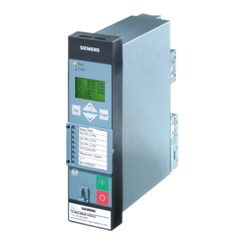
7SR10 Description of Operation
©2018 Siemens Protection Devices Limited Chapter 1 Page 2 of 77
Contents
Section 1: Introduction .......................................................................................................................................8
1.1 Current Transformer Circuits ..............................................................................................................8
1.2 External Resistors..............................................................................................................................8
1.3 Description ........................................................................................................................................8
1.4 Ordering Options ...............................................................................................................................9
1.5 Functional Diagram..........................................................................................................................11
1.6 Terminal Diagram ............................................................................................................................12
1.6.1 Terminal Diagram with Control Push Buttons ......................................................................12
Section 2: Hardware Description ......................................................................................................................14
2.1 General ...........................................................................................................................................14
2.2 Front Fascia ....................................................................................................................................15
2.2.1 Front Fascia with Control Push Buttons...............................................................................15
2.3 CB Open/Close ...............................................................................................................................15
2.4 Power Supply Unit (PSU).................................................................................................................16
2.5 Connectors......................................................................................................................................17
2.5.1 Connectors with Control Push Buttons ................................................................................17
2.6 Relay Information ............................................................................................................................17
2.7 Operator Interface............................................................................................................................19
2.7.1 Liquid Crystal Display (LCD) ...............................................................................................19
2.7.2 LCD Indication ...................................................................................................................19
2.7.3 Standard Keys ...................................................................................................................19
2.7.4 Protection Healthy LED ......................................................................................................20
2.7.5 Indication LEDs..................................................................................................................20
2.8 Current Inputs..................................................................................................................................20
2.9 Voltage Inputs .................................................................................................................................21
2.10 Binary Inputs ...................................................................................................................................21
2.11 Binary Outputs (Output Relays)........................................................................................................21
2.12 Virtual Input/Outputs ........................................................................................................................22
2.13 Self Monitoring ................................................................................................................................23
2.13.1 Protection Healthy/Defective...............................................................................................24
Section 3: Protection Functions ........................................................................................................................25
3.1 Current Protection: Phase Overcurrent (67, 51, 50)...........................................................................25
3.1.1 Directional Control of Overcurrent Protection (67)................................................................25
3.1.2 Instantaneous Overcurrent Protection (50) ..........................................................................26
3.1.3 Time Delayed Overcurrent Protection (51) ..........................................................................27
3.1.4 Current Protection: Voltage Controlled Overcurrent (51V)....................................................29
3.2 Current Protection: Derived Earth Fault (67N, 51N, 50N)...................................................................30
3.2.1 Directional Control of Derived Earth Fault Protection (67N)..................................................30
3.2.2 Instantaneous Derived Earth Fault Protection (50N) ............................................................31
3.2.3 Time Delayed Derived Earth Fault Protection (51N).............................................................32
3.3 Current Protection: Measured Earth Fault (67G, 51G, 50G)...............................................................34
3.3.1 Directional Control of Measured Earth Fault Protection (67G) ..............................................34
3.3.2 Instantaneous Measured Earth Fault Protection (50G).........................................................35
3.3.3 Time Delayed Measured Earth Fault Protection (51G) .........................................................36
3.4 Current Protection: Sensitive Earth Fault (67SEF, 51SEF, 50SEF)....................................................37
3.4.1 Directional Control of Sensitive Earth Fault Protection (67SEF)............................................37
3.4.2 Instantaneous Sensitive Earth Fault Protection (50SEF)......................................................38
3.4.3 Time Delayed Sensitive Earth Fault Protection (51SEF) ......................................................38
3.4.4 Current Protection: High Impedance Restricted Earth Fault - (64H)......................................40
3.4.5 Current Protection: Cold Load (51c)....................................................................................40
3.4.6 Current Protection: Negative Phase Sequence Overcurrent - (46NPS).................................41
3.4.7 Current Protection: Under-Current (37) ...............................................................................42
3.4.8 Current Protection: Thermal Overload (49)..........................................................................43
3.4.9 Voltage Protection: Phase Under/Over Voltage (27/59) .......................................................44
3.4.10 Voltage Protection: Negative Phase Sequence Overvoltage (47NPS) ..................................45
3.4.11 Voltage Protection: Neutral Overvoltage (59N) ....................................................................46
3.4.12 Voltage Protection: Under/Over Frequency (81) ..................................................................47
3.4.13 Power Protection: Power (32) .............................................................................................48
