Table of Contents
Preface..........................................................................................................................................................3
Open Source Software..................................................................................................................................7
1 Introduction................................................................................................................................................11
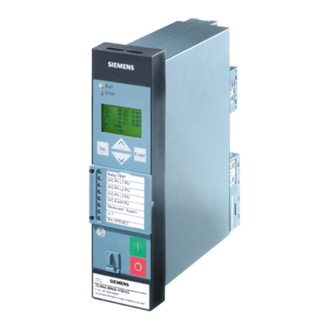
1.1 7SR46 Overcurrent and Earth Fault Relay Overview............................................................12
1.2 Ordering Options.............................................................................................................. 14
2 Device Functionality................................................................................................................................... 15
2.1 Front Fascia...................................................................................................................... 16
2.1.1 Overview.....................................................................................................................16
2.1.2 Liquid Crystal Display................................................................................................... 16
2.1.3 Keypad........................................................................................................................17
2.1.4 Light Emitting Diode (LED)...........................................................................................18
2.1.5 Local Flag.................................................................................................................... 20
2.1.6 Rating Label................................................................................................................ 20
2.2 Sensitivity ........................................................................................................................ 21
2.3 Binary Inputs ....................................................................................................................22
2.4 External Trip Input............................................................................................................ 24
2.5 Binary Outputs ................................................................................................................. 26
2.6 Pulse Output .................................................................................................................... 28
2.7 Remote Flag Output ......................................................................................................... 29
2.8 Resetting of LEDs, Trip Flag Indication, and Binary Outputs................................................ 30
2.9 Data Storage..................................................................................................................... 33
2.10 Real Time Clock (RTC)........................................................................................................34
3 Functions.................................................................................................................................................... 35
3.1 Functions Available in 7SR46 Argus Relay.......................................................................... 36
3.2 50 Instantaneous Overcurrent - Phase .............................................................................. 37
3.3 50N Instantaneous Earth Fault – Derived...........................................................................41
3.4 51 Time-Delayed Overcurrent – Phase............................................................................... 44
3.5 51N Time-Delayed Earth Fault – Derived............................................................................50
3.6 50LC/SOTF Switch onto Fault Protection............................................................................ 55
3.7 2nd Harmonic Block/Inrush Restraint (81HBL2).................................................................. 58
4 Technical Data............................................................................................................................................ 61
4.1 General Device Data..........................................................................................................62
4.2 50 Instantaneous Overcurrent - Phase............................................................................... 63
4.3 50N Instantaneous Earth Fault – Derived...........................................................................64
4.4 51 Time-Delayed Overcurrent - Phase................................................................................ 65
Reyrolle, 7SR46 Device, Manual 9
C53000-G7040-C103-1, Edition 10.2022
