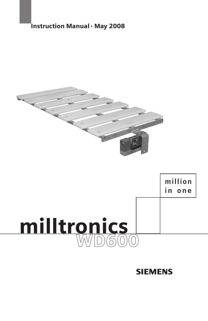
Siemens Milltronics WD600 User manual

Operating Instructions
Milltronics WD600
09/2016
Edition
Belt Scales

© Siemens AG 2015
Safety Guidelines
Warning notices must be observed to ensure personal safety as well as that of others, and to protect the product and the connected equipment.
These warning notices are accompanied by a clarification of the level of caution to be observed.
Qualified Personnel
This device/system may only be set up and operated in conjunction with this manual. Qualified personnel are only authorized to install and
operate this equipment in accordance with established safety practices and standards.
Unit Repair and Excluded Liability:
•The user is responsible for all changes and repairs made to the device by the user or the user’s agent.
•All new components are to be provided by Siemens.
•Restrict repair to faulty components only.
•Do not reuse faulty components.
Warning: Cardboard shipping package provides limited humidity and moisture protection. This product can only function properly and safely if
it is correctly transported, stored, installed, set up, operated, and maintained.
This product is intended for use in industrial areas. Operation of this equipment in a residential area may cause interference to several
frequency based communications.
Note: Always use product in accordance with specifications.
Copyright Siemens AG 2015. All Rights Reserved Disclaimer of Liability
This document is available in bound version and in
electronic version. We encourage users to purchase
authorized bound manuals, or to view electronic versions as
designed and authored by Siemens. Siemens will not be
responsible for the contents of partial or whole
reproductions of either bound or electronic versions.
While we have verified the contents of this
manual for agreement with the instrumentation
described, variations remain possible. Thus we
cannot guarantee full agreement. The contents of
this manual are regularly reviewed and
corrections are included in subsequent editions.
We welcome all suggestions for improvement.
Technical data subject to change.
European Authorized Representative
Siemens AG
Industry Sector
76181 Karlsruhe
Deutschland
•For a selection of Siemens level measurement manuals, go to:
www. siemens.com/processautomation. Select Products & Systems, then under Process Instrumentation, select
Level Measurement.
Manual archives can be found on the Support page by product family.
•For a selection of Siemens weighing manuals, go to:
www. siemens.com/processautomation. Under Products & Systems, select
Weighing and Batching Systems.
Manual archives can be found on the Support page by product family.
Milltronics WD600
___________________
___________________
___________________
___________________
___________________
___________________
___________________
___________________
___________________
Milltronics
Belt Scales
Milltronics WD600
Operating Instructions
09/2016
A5E38964753_AB
Introduction
1
Safety notes
2
Description
3
Installing/Mounting
4
Connecting
5
Commissioning
6
Service and maintenance
7
Technical data
8
Dimension drawings
9

Siemens AG
Division Process Industries and Drives
Postfach 48 48
90026 NÜRNBERG
GERMANY
Document order number: A5E38964753
Ⓟ
10/2016 Subject to change
Copyright © Siemens AG 2016.
All rights reserved
Legal information
Warning notice system
This manual contains notices you have to observe in order to ensure your personal safety, as well as to prevent
damage to property. The notices referring to your personal safety are highlighted in the manual by a safety alert
symbol, notices referring only to property damage have no safety alert symbol. These notices shown below are
graded according to the degree of danger.
DANGER
indicates that death or severe personal injury will result if proper precautions are not taken.
WARNING
indicates that death or severe personal injury may result if proper precautions are not taken.
CAUTION
indicates that minor personal injury can result if proper precautions are not taken.
NOTICE
indicates that property damage can result if proper precautions are not taken.
If more than one degree of danger is present, the warning notice representing the highest degree of danger will be
used. A notice warning of injury to persons with a safety alert symbol may also include a warning relating to property
damage.
Qualified Personnel
The product/system described in this documentation may be operated only by
personnel qualified
for the specific task
in accordance with the relevant documentation, in particular its warning notices and safety instructions. Qualified
personnel are those who, based on their training and experience, are capable of identifying risks and avoiding
potential hazards when working with these products/systems.
Proper use of Siemens products
Note the following:
WARNING
Siemens products may only be used for the applications described in the catalog and in the relevant technical
documentation. If products and components from other manufacturers are used, these must be recommended
or approved by Siemens. Proper transport, storage, installation, assembly, commissioning, operation and
maintenance are required to ensure that the products operate safely and without any problems. The permissible
ambient conditions must be complied with. The information in the relevant documentation must be observed.
Trademarks
All names identified by ® are registered trademarks of Siemens AG. The remaining trademarks in this publication may
be trademarks whose use by third parties for their own purposes could violate the rights of the owner.
Disclaimer of Liability
We have reviewed the contents of this publication to ensure consistency with the hardware and software described.
Since variance cannot be precluded entirely, we cannot guarantee full consistency. However, the information in this
publication is reviewed regularly and any necessary corrections are included in subsequent editions.

Milltronics WD600
Operating Instructions, 09/2016, A5E38964753_AB3
Table of contents
1 Introduction............................................................................................................................................. 5
1.1 The manual...............................................................................................................................5
2 Safety notes............................................................................................................................................ 7
2.1 General safety instructions .......................................................................................................7
3 Description.............................................................................................................................................. 9
3.1 Introduction ...............................................................................................................................9
3.2 Principle of operation..............................................................................................................10
4 Installing/Mounting................................................................................................................................ 11
4.1 Introduction .............................................................................................................................11
4.2 Conveyor considerations ........................................................................................................11
4.2.1 Control gates...........................................................................................................................12
4.2.2 Conveyor belting.....................................................................................................................12
4.2.3 Conveyor curvature.................................................................................................................12
4.2.4 Belt ploughs ............................................................................................................................13
4.2.5 Stacker conveyors ..................................................................................................................13
4.2.6 Conveyor trippers....................................................................................................................14
4.2.7 Skirt boards and sealing strips................................................................................................14
4.3 Load cell handling...................................................................................................................15
4.4 Installation precautions...........................................................................................................16
4.5 Installation procedure..............................................................................................................17
4.6 Idler alignment procedure.......................................................................................................18
5 Connecting ........................................................................................................................................... 21
5.1 Belt scale wiring......................................................................................................................21
6 Commissioning ..................................................................................................................................... 23
6.1 Calibration...............................................................................................................................23
6.2 Test Load................................................................................................................................23
6.3 Balancing ................................................................................................................................23
6.4 Final calibration.......................................................................................................................23
6.5 Zero calibration .......................................................................................................................24
6.6 Span calibration......................................................................................................................24
6.7 Material test ............................................................................................................................24
6.8 Re-rating .................................................................................................................................24
7 Service and maintenance...................................................................................................................... 25

Table of contents
4
Milltronics WD600
Operating Instructions, 09/2016, A5E38964753_AB
7.1 Maintenance........................................................................................................................... 25
7.2 Replacing a load cell.............................................................................................................. 25
7.3 Spare parts............................................................................................................................. 26
7.4 Technical support................................................................................................................... 26
8 Technical data ...................................................................................................................................... 27
8.1 Specifications......................................................................................................................... 27
9 Dimension drawings.............................................................................................................................. 29
9.1 Outline dimensions ................................................................................................................ 29

Milltronics WD600
Operating Instructions, 09/2016, A5E38964753_AB5
Introduction
1
Note
The Siemens weighing system is to be used only in the manner outlined in this manual,
otherwise protection provided by equipment may be impaired.
•
It is your responsibility to read this manual before installing and starting up any
component of the weighing system to which the belt scale is being applied.
1.1
The manual
This manual covers only belt scale installation, operation, and maintenance procedures.
Integrator and speed sensor operating instructions are available for download from our website:
Siemens weighing (http://www.siemens.com/weighing)
Follow these operating instructions for quick, trouble-free installation, and maximum accuracy
and reliability of your weighing system.
We always welcome suggestions and comments about manual content, design, and
accessibility. Please direct your comments to:
Technical publications (mailto:techpubs.smpi@siemens.com)

Introduction
1.1 The manual
6
Milltronics WD600
Operating Instructions, 09/2016, A5E38964753_AB

Milltronics WD600
Operating Instructions, 09/2016, A5E38964753_AB7
Safety notes
2
2.1
General safety instructions
CAUTION
Correct, reliable operation of the product requires proper transport, storage, positioning and
assembly as well as careful operation and maintenance. Only qualified personnel should
install or operate this instrument.
Note
Alterations to the product, including opening or improper repairs of the product, are not
permitted.
If this requirement is not observed, the CE mark and the manufacturer's warranty will expire.

Safety notes
2.1 General safety instructions
8Milltronics WD600
Operating Instructions, 09/2016, A5E38964753_AB

Milltronics WD600
Operating Instructions, 09/2016, A5E38964753_AB9
Description
3
3.1
Introduction
Milltronics WD600 Belt Scale
Milltronics WD600 belt scale is a low-to-medium capacity scale for light-to-medium belt loading.
It is designed to be inserted into either a flat roll idler (non-troughing) belt conveyor or a flat pan
slider belt conveyor for continuous weighing of dry bulk solids. WD600 is suitable for monitoring
such products as fertilizer, tobacco, animal feed pellets, and sugar.
WD600 belt scale consists of the following:
●weighbridge (slider deck)
●two precision load cells on mounting pads with weighbridge mounts
WD600 load cells output an electrical signal proportional to load, which is applied to the selected
Siemens belt scale integrator. Thus, weighing is accomplished without interrupting the process
and without affecting the process material.
Note
WD600 is an accurate and repeatable force sensor. Its performance is ultimately dependent
upon the
conveyor system and the quality of the installation and accuracy of the alignment.

Description
3.2 Principle of operation
10
Milltronics WD600
Operating Instructions, 09/2016, A5E38964753_AB
3.2
Principle of operation
Overview
①
Slider pad
②
Load cell
③
Top load cell mount
④
Bottom load cell mount
⑤
Conveyor stringer
Principle of operation
Belt scales work with an existing belt conveyor and the selected Siemens integrator. As material
moving along the conveyor belt travels over the belt scale, it exerts a force proportional to the
material load through the suspended weighdeck to the load cells.
The belt scale reacts only to the vertical component of the applied force. The resulting
movement in each load cell is sensed by its strain gauges. When the strain gauges are excited
by voltage from the electronic integrator, they produce an electrical signal proportional to weight,
which is then returned to the integrator. The vertical movement of the load cells is limited by the
positive overload stop incorporated into the design of the belt scale.

Milltronics WD600
Operating Instructions, 09/2016, A5E38964753_AB11
Installing/Mounting
4
4.1
Introduction
CAUTION
Installation shall be performed only by qualified personnel in accordance with local
governing regulations.
The belt scale is shipped from the factory as a single unit packed in a container for protection.
The weigh module must be removed from its package and inspected for physical damage. Be
sure the conveyor design meets the installation requirements for the belt scale.
Note
•
Use only approved conduit and conduit fittings or cable glands to maintain NEMA or IP
rating, as applicable.
•
Adjust conveyor stringers to be rigid, straight, parallel to, and square with the belt line in
the area of the scale installation.
•
Adjust pulleys to ensure that the conveyor belt tracks straight and centrally from the head
to the tail pulley.
•
The idler to be used on the scale and at least the next two approach and retreat idlers,
must be of the same style and manufacturer, and in good condition.
Prepare the site in accordance with the Siemens drawing(s) or by referring to the Belt Scale
Applications Guidelines (7ML19985GA01).
4.2
Conveyor considerations
The ideal placement of the belt scale depends on the conveyor system. This section provides
guidelines to determine belt scale placement.

Installing/Mounting
4.2 Conveyor considerations
12
Milltronics WD600
Operating Instructions, 09/2016, A5E38964753_AB
4.2.1
Control gates
The installation of a material feed control gate or similar device improves uniform flow of
material.
①
Control gate
②
Uniform material distribution
③
Belt scale
Note
Ensure steady and uniform material loading to the belt at or
near the same speed as the
conveyor belt.
4.2.2
Conveyor belting
Variations in the number of belt plies, the cover thickness and the type and number of splices in
a given belt cause considerable change in the weight per unit length of the belt. During the
course of zero calibrations, belt scales average the weight of the belt over one complete circuit
of the belt. Large deviations from the average adversely affect the zero calibrations.
4.2.3
Conveyor curvature
Vertical curvature (varied heights on one belt) is common in conveyor design, but creates
difficulties for belt scales if not dealt with correctly. The curvature, whether concave (internal) or
convex (external), disturbs the idler alignment, if the scale is installed in the area of curvature.
The concave curve tends to lift the belt off of the idlers in the area of curvature as belt loading
decreases, adversely affecting the zero calibration.
Note
Avoid locating the scale within the tangents of scale curvature.

Installing/Mounting
4.2 Conveyor considerations
Milltronics WD600
Operating Instructions, 09/2016, A5E38964753_AB13
Concave
①
Minimum 12 m (40 ft)
②
Tangents
③
Belt scale
Convex
①
Minimum 6 m (20 ft)
②
Minimum 12 m (40 ft)
③
Tangents
④
Belt scale
4.2.4
Belt ploughs
Belt ploughs or any conveyor or material control device that changes the profile of the carrying
belt in or near the scale area is not recommended. These devices can negatively affect the belt
scale idler alignment and usually create drag on the belt which the scale senses as a material
force of load.
Note
Do not install the scale within 9 m (30 ft) of belt ploughs or similar devices that contact the
material or belt.
4.2.5
Stacker conveyors
Any conveyor that is not a permanent structure, which varies in its incline, elevation or profile is
not considered a good installation for an accurate belt scale. A belt scale can be used effectively
in this conveyor type, but requires special setup. Siemens offers an inclinometer for use with
variable incline conveyors.

Installing/Mounting
4.2 Conveyor considerations
14
Milltronics WD600
Operating Instructions, 09/2016, A5E38964753_AB
4.2.6
Conveyor trippers
Note
On a convey
or with a tripper car, locate the scale under the recommendations for vertical
curves, but with the tripper fully retracted.
4.2.7
Skirt boards and sealing strips
Sometimes it is necessary to extend the infeed skirt boards and sealing strips the full length of
the conveyor. This can create problems in weighing accuracy if the sealing strips exert excess
force when contacting the belt and indirectly upon the idlers, especially where pinching occurs.
The situation adversely affects the zero calibrations.
Note
If possible, remove skirting in scale area. If not, adjust skirting so sealing strip does not put
excess force on the belt or allow pinching of material.

Installing/Mounting
4.3 Load cell handling
Milltronics WD600
Operating Instructions, 09/2016, A5E38964753_AB15
4.3
Load cell handling
The WD600 belt scale is designed for low to medium-capacity operation and uses two load cells.
Although the load cells are protected by shipping stops that keep the cells from moving, care
should be taken when handling the scale to avoid damaging the cells. The stops are screws that
are 38mm (1.5") long. The screw threads into the bottom of the load cell and pulls the cell
against the overload stop, use a 0.5mm (.02") shim between the load cell and overload stop to
prevent damage. When handling the WD600 during installation and set-up, make sure the stops
remain in place. Reinstall both shipping stops during maintenance or prolonged shutdown.
①
Weigh deck
②
Belt
③
Top load cell mount
④
Overload screw
⑤
Shipping screw
⑥
Load cell
⑦
Bottom load cell mount

Installing/Mounting
4.4 Installation precautions
16
Milltronics WD600
Operating Instructions, 09/2016, A5E38964753_AB
4.4
Installation precautions
The following precautions should be observed when handling the scale.
●Do not pry on the idler, its mountings, or the cells directly.
●Do not stand or lean on the scale.
●Avoid shock from blows of a hammer when trying to position the scale during installation.
●Do not lift the scale by the top load cell mounting brackets.
CAUTION
Arc welding
Use extreme caution when arc welding in the area of the belt scale. Ensure that no
welding current can flow through the belt scale. Welding currents passing through the
scale can functionally damage the load cells.

Installing/Mounting
4.5 Installation procedure
Milltronics WD600
Operating Instructions, 09/2016, A5E38964753_AB17
4.5
Installation procedure
①
Belt
②
Weigh span
③
Weigh deck
④
Minimum 4.75" (121 mm), both sides must be equal
⑤
Test weight hanger bracket
⑥
Load cell
⑦
Existing slider belt support
1. Remove the existing flat roll idler (or flat slider pan) from the area selected to locate the belt
scale assembly.
2. Drill four 8 mm (5/16") diameter mounting holes. This will allow clearance for 6 mm bolts.
Note
Slotting the holes vertically will permit greate
r adjustment capability.
3. Position the scale with the weighdeck towards the head end (discharge) of the conveyor and
the load cells toward the tail end (infeed).
–Raise the conveyor belting to provide room for the installation of the scale.
4. Insert the scale (modules) onto the conveyor.
–Insert four M6x1 bolts through the conveyor frame and through the holes in the sides of
the load cell mount pads.
–Secure the bolts, finger tight only.

Installing/Mounting
4.6 Idler alignment procedure
18
Milltronics WD600
Operating Instructions, 09/2016, A5E38964753_AB
5. Make sure there is at least 13 mm (½") of clearance between the return belt and the WD600.
–In some conveyors, it may be necessary to install a return idler roller adjacent to the scale
to deflect the return belt past the scale.
6. Position the scale so that it is parallel to the conveyor and square to the stringer.
–Place the weighdeck on the top load cell mount.
–Level the weighdeck and tighten the bolts sufficiently to keep the load cell mount pads in
place until final adjustment.
NOTICE
Off-center or off-square installation can result in poor belt tracking and scale
inaccuracy.
4.6
Idler alignment procedure
Establishing good idler alignment is the most important part of the installation procedure. Scale
accuracy is directly affected by alignment.
Note
Improperly aligned idlers could cause unwanted forces to be
applied to the weighbridge,
resulting in calibration and measurement errors.
1. Remove the shipping stops to free the weighing mechanism.
–Keep the screws stored in a convenient place for use during maintenance or at other
times when protection of the cells is necessary.
2. Align and level the weighbridge in the weighing area by raising or lowering the load cell
mount pads in their slots.
–The weighing area includes the scale and the approach and retreat idlers/sliders. For
conventional flat idler roll conveyors, two additional idler rolls should be included in the
alignment procedure.
3. Align and level the idlers (pans on a slider pan conveyor) in the weighing area by shimming
the scale deck, the two approach idlers, and the two retreat idlers, until they are within ± 0.8
mm (1/32") of each other.
–Be sure to check that the idlers are centered and squared to the conveyor during the
shimming process.
Other manuals for Milltronics WD600
1
Table of contents
Other Siemens Scale manuals

Siemens
Siemens Milltronics WD600 User manual

Siemens
Siemens SIWAREX WP231 User manual

Siemens
Siemens milltronics User manual

Siemens
Siemens MAMMOMAT Operating and maintenance instructions

Siemens
Siemens Milltronics MUS User manual

Siemens
Siemens SIWAREX FTA Application guide

Siemens
Siemens Milltronics MCS User manual

Siemens
Siemens milltronics User manual

Siemens
Siemens Milltronics MMI User manual