2
TABLE 1
ADDR 4321ADDR 4321
ILLEGAL O O O O8XOOO
1 OOOX9XOOX
2OOXO10 X O X 0
3OOXX11 X O X X
4OXOOILLEGAL X X O O
5OXOXILLEGAL X X O X
6OXXOILLEGAL X X X O
7 O X X X ILLEGAL XXXX
X = SWITCH CLOSED OR ON, 0= SWITCH OPEN OR OFF
NOTE:
To open a dipswitch, press down on the side of
the dipswitch marked OPEN. To close a
dipswitch, press down on the side of the
dipswitch opposite the side marked OPEN.
To open a slide switch, push the slide to the
side opposite the side marked ON. To close a
slide switch, push the slide to the side marked ON.
Do NOT install the card in its edge connector
until ALL OMM-1 field wiring is completed and
checked for shorts, opens, and other faults.
Refer to the Wiring Checkout Chart. Replace
the card in its protective bag if the wiring is not
complete.
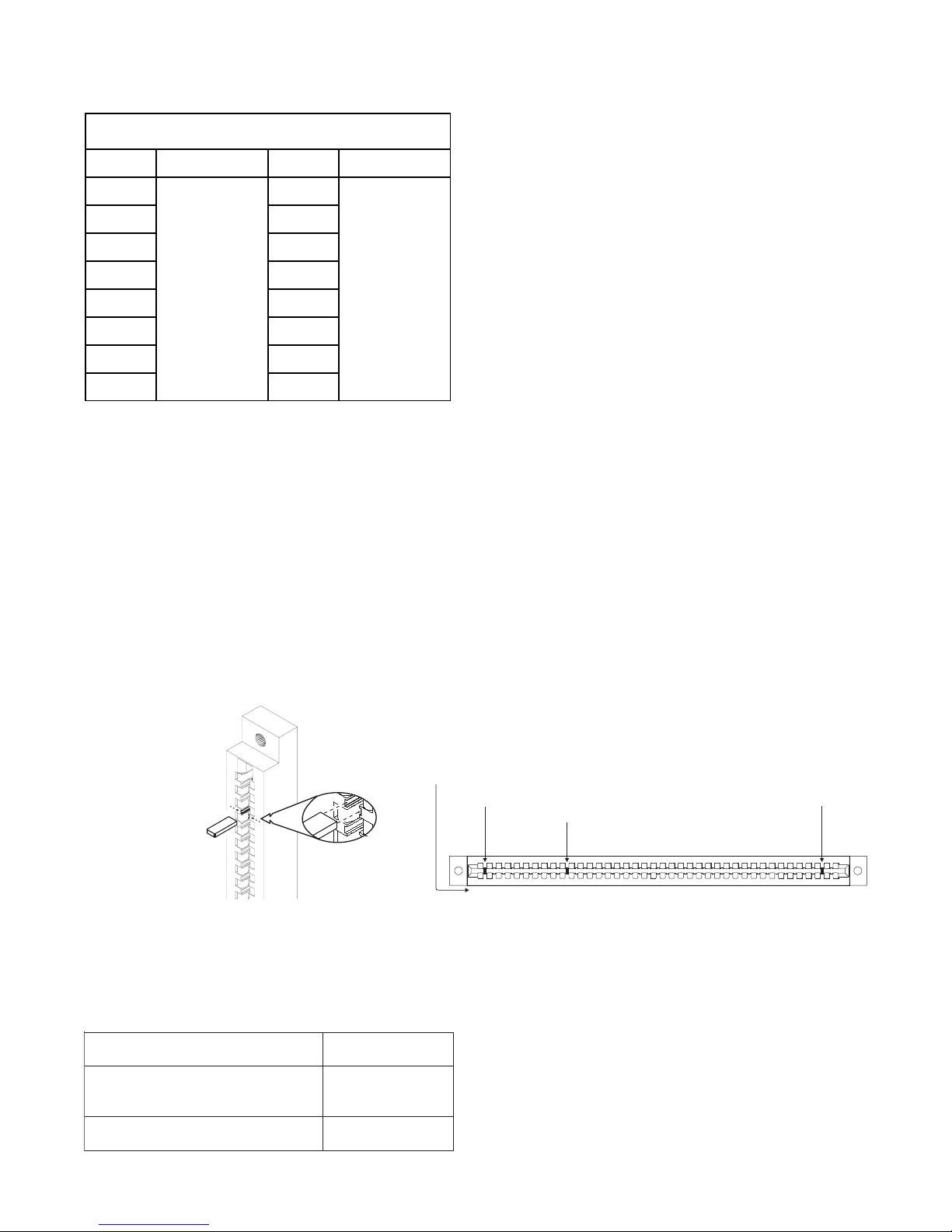
Find the card slot key provided in the installation
kit with the ZCT-8B board. Place the card slot
key
in the OMM-1 edge connector for the ZCT-8B
as
shown in Figure 2. See Figure 3 for the exact
Figure 2
Placing the Card Slot Key in the OMM-1 Figure 3
Location of User Key for ZCT-8B
ELECTRICAL RATINGS
179
218
FACTORY KEY 1
OMM PIN NUMBERS
FACTORY KEY 2
USER KEY
17
20
19
80
location of the key for this module. This prevents
installation of any other card type in the ZCT-8B
slot. Two other keys already installed in the
OMM-1 prevent reverse installation of the card in
the OMM-1 edge connectors. (See Figure 3.)
Place the card in its card edge connector cor-
rectly. The components on the board must face
the 22 position terminal block where the wiring is
terminated. Press the card firmly in place to be
sure it is seated properly in the edge connector.
tnerruCeludoMCDV5evitcAAm51
tnerruCeludoMCDV42evitcA Am01+Am01 enozevitcarep
tnerruCeludoMCDV42ybdnatSAm51
Maximum wire size: 14 AWG twisted pair, shielded
Minimum wire size: 18 AWG twisted pair, shielded
Maximum loop resistance: 10 ohms for both wires.
Outputs: Supervisory 9 VDC, 9mA max
Activated 12.5 VDC, 300mA max
End of line resistor: 10K, ¼W, ±1% (P/N 140-383467)


 On OpenStage Quick reference guide")


