manuals.online logo
Brands
  1. Home
  2. •
  3. Brands
  4. •
  5. Siemens
  6. •
  7. Temperature Controllers
  8. •
  9. Siemens RDUxxx Series User manual

Siemens RDUxxx Series User manual

CE1B3061en / 05.02.2003 Subject to alteration Siemens Building Technologies / HVAC Products
Operating Instructions RDU…
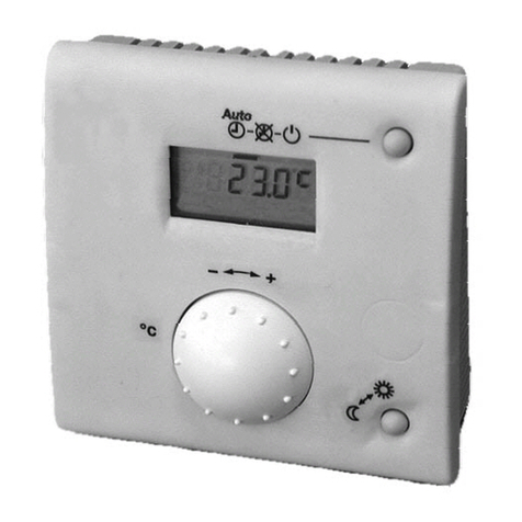
RDU... – the temperature controller that allows you to easily set the room temperature you want. You have
2 choices. You can either rely on the factory settings or make adjustments that suit your individual needs.
Display Settings and operation
Normal operation
Energy saving mode
Display of current
room temperature
or new setpoint
Warmer / colder
Adjustment of
temperature setpoints
3061Z01en
Heating valve open
Cooling valve open
Display of actual
room temperature
Buttons for setpoint adjustments
Heating mode, Off, cooling mode
Operating mode
selector
(RDU50.2)
Are your rooms too warm or too cold?
Normal operation
The + / - buttons allow you to increase or decrease the current room temperature setpoint in steps of 0.5 °C.
To do this, proceed as follows:
•Press or once
The setpoint display starts flashing
•Press the buttons again to change the room temperature setpoint
10 seconds after the last press, the new temperature setpoint will automatically be stored. The display stops flashing.
Changing from heating to cooling mode
/
Automatic changeover
With the RDU50.2, manual changeover modes selector
from heating mode, Off to cooling mode.
Off = out of operation.
Display shows that the heating output is active
Display shows that the cooling output is active
Changing from normal operation to energy
saving mode
/ Changeover from normal operation to energy saving mode
takes place automatically via an external contact
(window switch / remote operation switch, etc.).
(Exception with type RDU50.2 in Off mode)
Display shows normal operation.
Display shows energy saving mode.
Energy saving mode
If you want to change the factory-set temperature
setpoints (16 °C for heating and 28 °C for cooling), follow
the procedure given below (“Changing the control
parameters”).
Important:
The setpoint of energy saving mode can be set to Off.
This means that the controller is not active in energy
saving mode and the parameter display shows Off.
Risk of frost!
CE1B3061en / 05.02.2003 Subject to alteration Siemens Building Technologies / HVAC Products
Commissioning (by qualified HVAC staff)
Para-
meter Controller’s parameter factory settings: Setting range
(all settings can be made in increments of 0.5 K) RDU20 RDU50 RDU50.2
P01 Setpoint of heating in energy saving mode
(operating mode changeover switch activated) 16 °C0: corresponds to Off (display Off) 5…18 °C
P02 Setpoint of cooling in energy saving mode
(operating mode changeover switch activated) 28 °C0: corresponds to Off (display Off) 24…35 °C
P03 Minimum setpoint limitation in normal mode 5 °C5…20 °C
P04 Maximum setpoint limitation in normal mode 35 °C21…35 °C
P05 Heat-cool changeover switching point cooling 16 °C10…25 °CX
P06 Heat-cool changeover switching point heating 28 °C27…40 °CX
P07 Sensor calibration 0 K -3…+3
P08 P-band in heating mode 2 K 0.5…+4 K
P09 P-band in cooling mode 1 K 0.5…+4 K
Integral action time X
P10 Integral action time (only with modulating PI control, DIP switch no. 2 is set to ON) 5 min. 1…10 min. (increments of 1 min.) XX
Minimum output limitation in cooling mode (normal operation) 0 % 0...100 % (increments of 10 %) X
P11
Actuator running time (only with modulating PI control, DIP switch no. 2 is set to ON) 150 s 50...150 s (increments of 10 s) XX
P12 Active temperature sensor (no setting, display only) -1: room temperature sensor active
2: return air temperature sensor active
P13 Value of current room temperature reading (no setting, display only) -0…49 °C = current temperature value
P14 Value of current heat-cool changeover temperature reading including indication of current
mode ( ,) (no setting, display only) -
100 = input open (no sensor connected, heating mode ( ))
0…49 °C = current temp. value
00 = input bridged, cooling mode ( )
P15 Test mode for checking the actuator direction (note that this parameter can be quit only if the
setting is back at “---” and by pressing buttons + and – simultaneously) ---
“---“ = no signal on outputs Y1 and Y2
OPE = output Y1 forced open
CLO = output Y2 forced open
XX
Changing the control parameters
(To optimize the control performance, a number of control parameters
can be adjusted. This can also be made during operation without
opening the controller.
Do you want to change the control parameters of the heating and / or
cooling setpoints in the normal or energy saving mode? Or do you
want to increase / decrease the switching differential in heating and
cooling mode?
Then, proceed as follows:
(For factory settings, see above under “Commissioning)
1. Normal operation mode
2. Press the + and – buttons simultaneously for a min. of 3
and a max. of 5 seconds. Release them and within 2
seconds, press the + button again for 3 seconds. The
display will show “P01”.
3. Select the required parameter by repeatedly pressing
the + or – button:
P01 P0 2 P14 P15
+-+-+
--
+
3055z01
4. Press the + and – buttons simultaneously, the current
value of the selected parameter appears, which can
be changed by repeatedly pressing the + or – button.
5. By pressing buttons + and - simultaneously again or
5 seconds after the last press of a button, the last
parameter will be displayed again.
6. If you wish to display and change additional
parameters, repeat steps 3 through 5.
7. 10 seconds after the last display or setting,
all changes will be stored.
If the room temperature displayed by the controller does not agree with
the temperature effectively measured, the temperature sensor can be
recalibrated. For that purpose, parameter P07 must be changed
Proceed as described under “Changing the control parame-
ters” and follow steps 1 through 3 to select parameter P07.
With step 4, the room temperature displayed can now be
matched to the temperature effectively measured. Each push
of the + or – button changes the temperature by + or –
0.5 °C up to a maximum of + / - 3 °C.
With step 7, the recalibration is automatically stored 10
seconds after the last readjustment.
Legend to table
Adjustable:please record all changes you make
Not adjustable / display only
XNot adjustable / no display
Other Siemens Temperature Controllers manuals

Siemens SIMATIC S5 User manual

Siemens

Siemens SIMATIC S5 User manual

Siemens QAX30.1 User manual

Siemens

Siemens QAX30.1 User manual

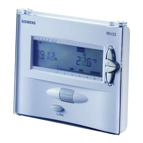
Siemens REV23 User manual

Siemens

Siemens REV23 User manual

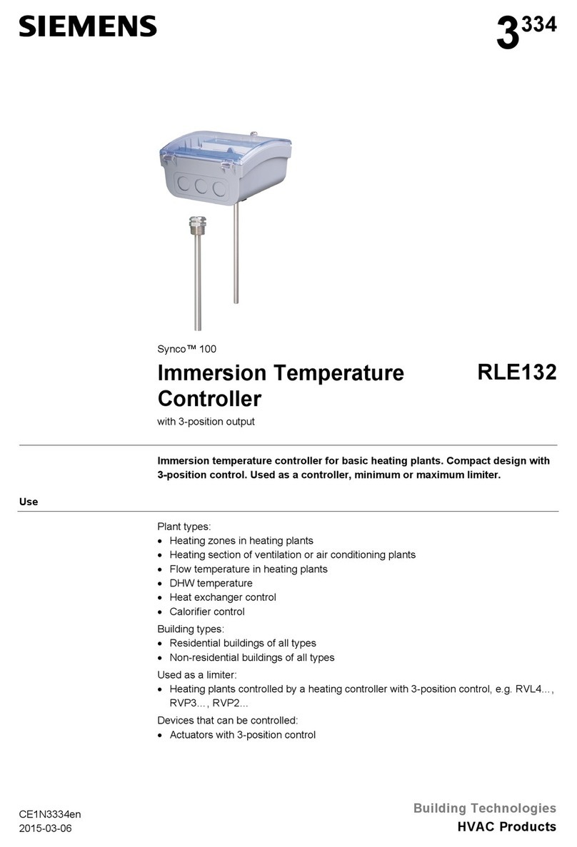
Siemens RLE132 User manual

Siemens

Siemens RLE132 User manual

Siemens RDE10.1DHW User manual

Siemens

Siemens RDE10.1DHW User manual

Siemens 24RFDC/SET User manual

Siemens

Siemens 24RFDC/SET User manual

Siemens REA22 Operator's manual

Siemens

Siemens REA22 Operator's manual

Siemens QAA2290.EWSC User manual

Siemens

Siemens QAA2290.EWSC User manual

Siemens RDD310 User manual

Siemens

Siemens RDD310 User manual

Siemens Synco 900 Guide

Siemens

Siemens Synco 900 Guide

Siemens QAX32.1 User manual

Siemens

Siemens QAX32.1 User manual

Siemens AVS13.399 User manual

Siemens

Siemens AVS13.399 User manual

Siemens RCC30 User manual

Siemens

Siemens RCC30 User manual

Siemens RDF20U User manual

Siemens

Siemens RDF20U User manual

Siemens RDU50U Owner's manual

Siemens

Siemens RDU50U Owner's manual

Siemens Expert Series Quick start guide

Siemens

Siemens Expert Series Quick start guide

Siemens REV23.03RF User manual

Siemens

Siemens REV23.03RF User manual

Siemens QAW910 User manual

Siemens

Siemens QAW910 User manual

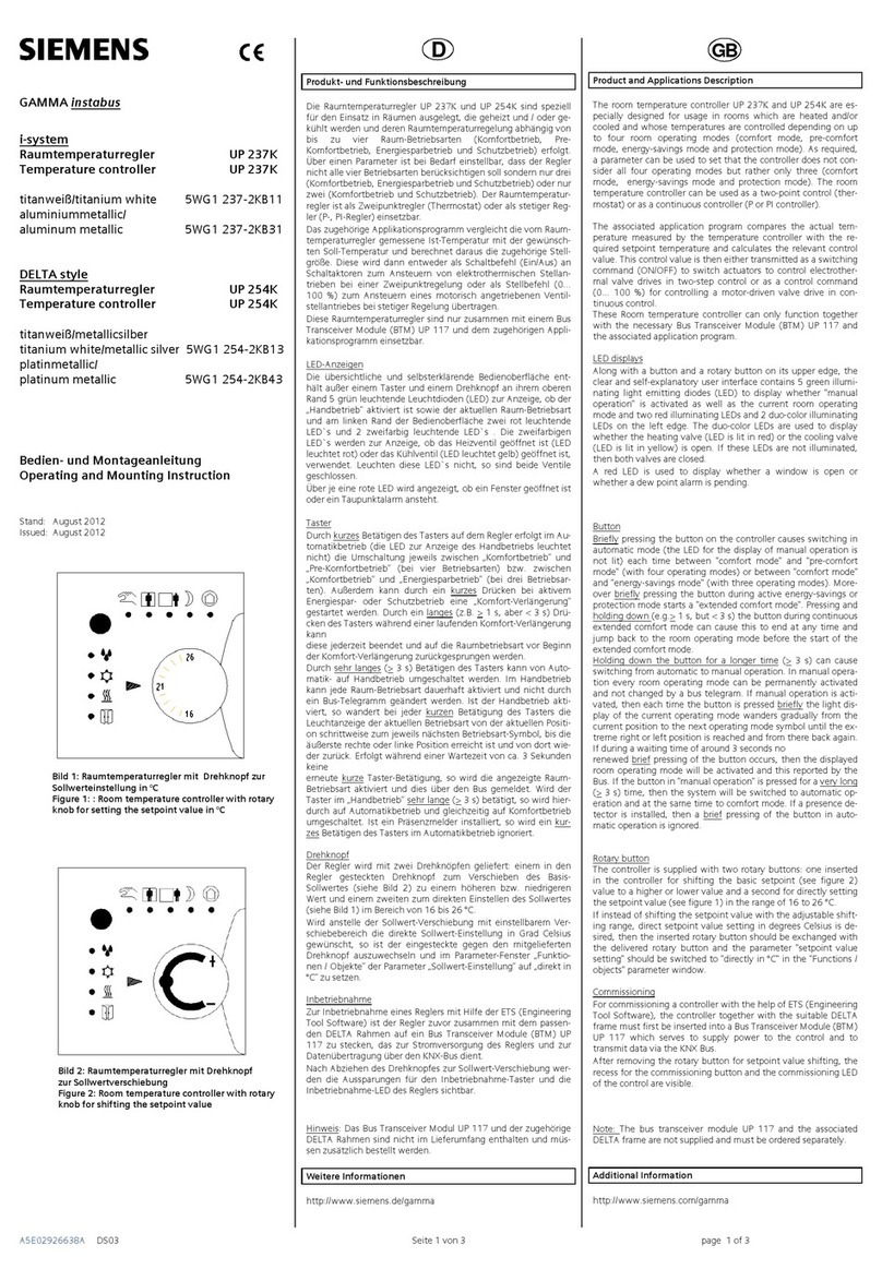
Siemens UP 237K User manual

Siemens

Siemens UP 237K User manual

Siemens BPS242RF User manual

Siemens

Siemens BPS242RF User manual

Siemens QAA70 User manual

Siemens

Siemens QAA70 User manual

Siemens SITRANS TSinse rt Administrator guide

Siemens

Siemens SITRANS TSinse rt Administrator guide

Siemens SITRANS TS100 Administrator guide

Siemens

Siemens SITRANS TS100 Administrator guide

Siemens HEATWELL RDE Series Operator's manual

Siemens

Siemens HEATWELL RDE Series Operator's manual

Popular Temperature Controllers manuals by other brands

Vescent SLICE-QT quick start guide

Vescent

Vescent SLICE-QT quick start guide

Atmel AT30TK175 Hardware user's guide

Atmel

Atmel AT30TK175 Hardware user's guide

Thermal Care Aquatherm RQE Operation, installation, and maintenance manual

Thermal Care

Thermal Care Aquatherm RQE Operation, installation, and maintenance manual

Elko RFTC-10/G Assembly instruction and manual

Elko

Elko RFTC-10/G Assembly instruction and manual

NPI MTC-20/2S Operating instructions and system description

NPI

NPI MTC-20/2S Operating instructions and system description

IFM TT 9 Series operating instructions

IFM

IFM TT 9 Series operating instructions

IKA IKATRON ETS-D5 operating instructions

IKA

IKA IKATRON ETS-D5 operating instructions

Hanyoung TD500 user guide

Hanyoung

Hanyoung TD500 user guide

Clas Ohlson WTH450H instruction manual

Clas Ohlson

Clas Ohlson WTH450H instruction manual

QUPIT Lisa installation manual

QUPIT

QUPIT Lisa installation manual

Danfoss ECL Comfort 110 quick guide

Danfoss

Danfoss ECL Comfort 110 quick guide

BAPI BAPI-Stat 4 X-Combo operating instructions

BAPI

BAPI BAPI-Stat 4 X-Combo operating instructions

Tempco TEC-9090 user manual

Tempco

Tempco TEC-9090 user manual

Tempco TEC-902 instruction manual

Tempco

Tempco TEC-902 instruction manual

alre RTERU-010.715# Series Operating and installation instructions

alre

alre RTERU-010.715# Series Operating and installation instructions

INCOE MV3 Series instruction manual

INCOE

INCOE MV3 Series instruction manual

Pentair DigiTrace RTD50CS installation instructions

Pentair

Pentair DigiTrace RTD50CS installation instructions

ITALCOPPIE SENSORI EVOMINI SCAT A quick start guide

ITALCOPPIE SENSORI

ITALCOPPIE SENSORI EVOMINI SCAT A quick start guide

manuals.online logo
manuals.online logoBrands
  • About & Mission
  • Contact us
  • Privacy Policy
  • Terms and Conditions

Copyright 2025 Manuals.Online. All Rights Reserved.