manuals.online logo
Brands
  1. Home
  2. •
  3. Brands
  4. •
  5. Siemon
  6. •
  7. Cables And Connectors
  8. •
  9. Siemon OptiFuse MPO SPLICE-ON User manual

Siemon OptiFuse MPO SPLICE-ON User manual

OptiFuse MPO SPLICE-ON Connector Instructions
From the main menu
press select fiber type.
2After selecting fiber type
press “Return”.
31
Select 12 strand and
press “Return”
4From the main menu select
Sleeve type.
5Select MPO Sleeve type
and press “Return”.
Set Fusion
Condition
From the main menu select
Arc test “on”, A sample section of
ribbon fiber is provided with the
connector for this purpose.
67
Tools
Set Fusion
Condition
Push and hold the
“power button” for more
than 1 sec.
Note: See operation
manual of T-71M12
Note: See operation
manual of T-71M12
Note: See operation
manual of T-71M12
Note: See operation
manual of T-71M12
Note: See operation
manual of T-71M12
Note: See operation
manual of T-71M12
Note: See operation
manual of T-71M12
INS_100.25411.00.qxp_C 1/26/18 3:29 PM Page 1
OptiFuse MPO SPLICE-ON Connector Instructions
10
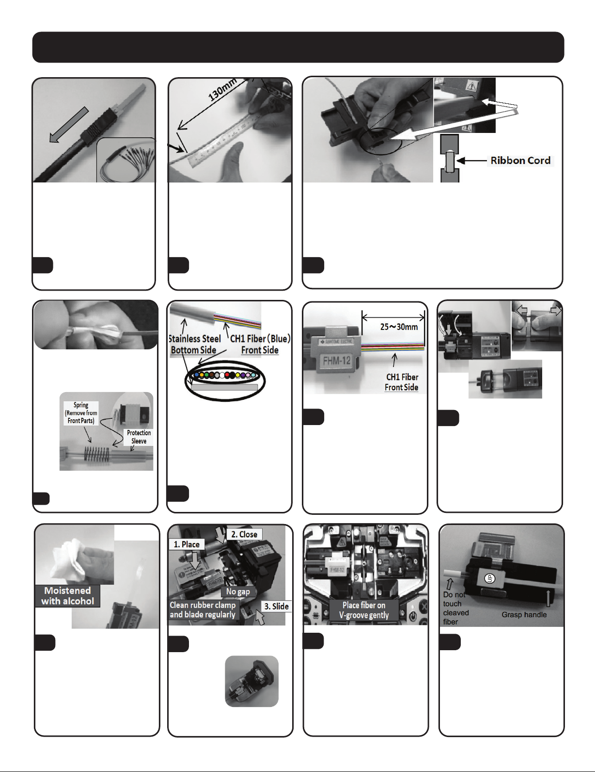
Slide rear parts onto the ribbon
cord.
8
Cut legs to desired length.
Mark off at 130mm from end of
cord.
9
Slide spring and then heat
shrink protection sleeve onto
the ribbon
11
Orient sleeve as shown
above.
12
Remove the ribbon coating
using the JR-6 unit. Ensure
unit is set to high temperature
for best results.
13 Set ribbon fiber in fiber
holder with between 25
and 30mm exposed as shown.
14
Use a fiber optic cleaning
paper moistened with
alcohol to remove any debris.
Gently pull away from jacket.
15
Use LYNX2-CORDTOOL-2&3 to make a slit in cord.
Set the Ribbon cord on “3mm” groove perpendicularly at 130mm
mark as shown and pull tool toward the end of the cord.
Cleave the fiber using the
FC-6M cleaver.
Place the fiber holder with
the cleaved fiber into the
fusion splicer on the left hand side.





Place MT STUB into hold-
er with “UP” text facing
upwards. After stub is set in the
holder, close the holder covers.
17 18
16
Note: The FC-8R cleaver can
also be used with same steps
INS_100.25411.00.qxp_C 1/26/18 3:30 PM Page 2
130mm
mark
Fold back the inner jacket, Kevlar
yarn, and outer jacket to the
marked 130mm line and secure
with tape.
OptiFuse MPO SPLICE-ON Connector Instructions
Place the fiber holder with the MT-STUB into the fusion splicer
on the right hand side. Close the Fusion splice cover. Ensure
that the heat shrink tube and spring are outside of the cover.
19 If fiber position does not align, remove affected splice holder
and gently replace it into the splicer. To begin splice process
press the start icon.
20
Continue to maintain
tension and gently
remove the splice stub
from the splice unit.
23 Gently slide the heat
shrink sleeve to the MT
STUB. Ensure that the
sleeve is not twisted.
2422
Press the heater button to
commence heating
process.
Disassemble rear parts.
Be sure to pull the boot off
the Kevlar stopper before
unscrewing from rear stopper.
26 27
While lightly maintaining
tension open the left
splice holder cover first
and then open the right
hand cover.
21 After the splicing proce-
dure is complete slide
the heat shrink sleeve to
the holder
Gently set sleeve into heater.
25
Ensure sleeve is in position
with metal side of sleeve flat
on bottom of heat chamber
before proceeding with
heating.
INS_100.25411.00.qxp_C 1/26/18 3:30 PM Page 3
INS_OptifuseMPOSpliceOnConnector_Rev. B7/21 100.25411.00
© 2018 The Siemon Company
To assist safe installations, comply with the following:
A. Use caution when installing or modifying
telecommunications circuits.
B. Never touch uninsulated wire terminals unless
the circuit has been disconnected.
C. Never install this device in a wet location.
D. Never install wiring during a lightning storm.
Worldwide Headquarters
North America
Watertown, CT USA
Phone (1) 860 945 4200
OptiFuse MPO SPLICE-ON Connector Instructions
Slide rear parts and remove dummy cap. Cut outer jacket (thin-
ner wall) 1-2 in. back.
28 Remove front housing dust cap. Insert MT STUB into front
housing. Align window in MT STUB with key ridge in front
housing. Gently slide spring over the heat shrink sleeve. Ensure
spring seats inside rear stopper. Gently push Rear Stopper forward
until a “click” is heard. Place dust cap over end of connector to
protect end face.
29
30 Slide the Kevlar stopper
forward.
Carefully cut the jacket sheaths in a chevron shape and place
on either side of the of the rear kevlar stopper as shown above.
31 32 Bring the parts/compo-
nents closer to each
other and straighten the
fibers covered with the
Kevlar in the sheath.
Screw Kevlar stopper to
rear stopper.
When Kevlar stopper is
fully tightened cut excess
Kevlar flush to housing.
Slide the furcation tube
boot forward (do not twist)
until fully seated.
33 34
www.siemon.com
INS_100.25411.00.qxp_C 1/26/18 3:30 PM Page 4

Other Siemon Cables And Connectors manuals

Siemon Z-PLUG User manual

Siemon

Siemon Z-PLUG User manual

Siemon LC Bladepatch User manual

Siemon

Siemon LC Bladepatch User manual

Siemon TERA User manual

Siemon

Siemon TERA User manual

Siemon 10G 6 User manual

Siemon

Siemon 10G 6 User manual

Popular Cables And Connectors manuals by other brands

Hubbell HBLC40123 installation instructions

Hubbell

Hubbell HBLC40123 installation instructions

Philips SWV3433W Specification sheet

Philips

Philips SWV3433W Specification sheet

GoMax Electronics SP-5008IZ user manual

GoMax Electronics

GoMax Electronics SP-5008IZ user manual

AVGear UDA2-V2 user manual

AVGear

AVGear UDA2-V2 user manual

PXM PX725 user manual

PXM

PXM PX725 user manual

PCB Piezotronics 045M29 Installation and operating manual

PCB Piezotronics

PCB Piezotronics 045M29 Installation and operating manual

Philips SWV3431W Specification sheet

Philips

Philips SWV3431W Specification sheet

prophecy gofanco PRO-HD21Split2P user guide

prophecy

prophecy gofanco PRO-HD21Split2P user guide

Gleason Reel Universal Cable Reel-Drive Drive UE32 Installation and maintenance instructions

Gleason Reel

Gleason Reel Universal Cable Reel-Drive Drive UE32 Installation and maintenance instructions

Monacor HDMS-1042 manual

Monacor

Monacor HDMS-1042 manual

PROEL PLCNTR user manual

PROEL

PROEL PLCNTR user manual

Ikelite 4102.15 instruction manual

Ikelite

Ikelite 4102.15 instruction manual

Staubli CombiTac direqt Assembly instructions

Staubli

Staubli CombiTac direqt Assembly instructions

Eaton COOPER POWER SERIES installation instructions

Eaton

Eaton COOPER POWER SERIES installation instructions

TRENDnet TU2-EX5 Specifications

TRENDnet

TRENDnet TU2-EX5 Specifications

Philips SWA3520 Specifications

Philips

Philips SWA3520 Specifications

E+E Elektronik EE75 manual

E+E Elektronik

E+E Elektronik EE75 manual

Brodit 942750 Quick start quide

Brodit

Brodit 942750 Quick start quide

manuals.online logo
manuals.online logoBrands
  • About & Mission
  • Contact us
  • Privacy Policy
  • Terms and Conditions

Copyright 2025 Manuals.Online. All Rights Reserved.