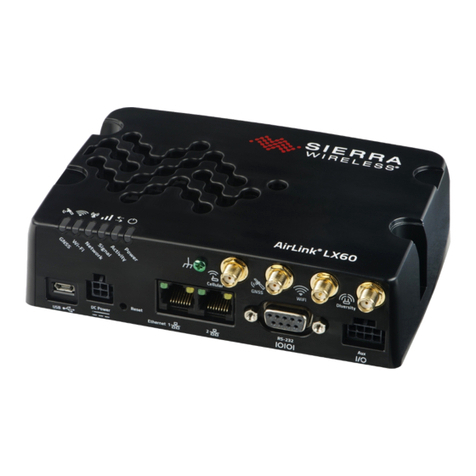
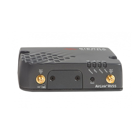
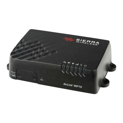
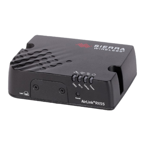
Sierra Wireless RX55 Installation manual

AirLink RX55
Hardware User Guide
41114494 Rev. 1 September 2022

AirLink RX55 Hardware User Guide
Rev. 1 September 2022 2 41114494
Important
Notice
Due to the nature of wireless communications, transmission and reception of data can
never be guaranteed. Data may be delayed, corrupted (i.e., have errors) or be totally lost.
Although significant delays or losses of data are rare when wireless devices such as the
Sierra Wireless product are used in a normal manner with a well-constructed network, the
Sierra Wireless product should not be used in situations where failure to transmit or
receive data could result in damage of any kind to the user or any other party, including
but not limited to personal injury, death, or loss of property. Sierra Wireless accepts no
responsibility for damages of any kind resulting from delays or errors in data transmitted
or received using the Sierra Wireless product, or for failure of the Sierra Wireless product
to transmit or receive such data.
Safety and
Hazards
Do not operate the Sierra Wireless product in areas where blasting is in progress, near
medical equipment, near life support equipment, or any equipment which may be
susceptible to any form of radio interference. In such areas, the Sierra Wireless product
MUST BE POWERED OFF. The Sierra Wireless product can transmit signals that could
interfere with this equipment.
The driver or operator of any vehicle should not operate the Sierra Wireless product while
in control of a vehicle. Doing so will detract from the driver or operator’s control and
operation of that vehicle. In some states and provinces, operating such communications
devices while in control of a vehicle is an offence.
The RX55 platform is classified to ANSI/ISA 12.12.01-2016 and CSA C22.2#213 and are
suitable for use in Class 1, Division 2, Groups A, B, C and D T6, and Class I Zone 2
Group IIC T6 classified Hazardous Locations.
The following warnings and instructions apply:
Warning: EXPLOSION HAZARD–SUBSTITUTION OF COMPONENTS MAY IMPAIR
SUITABILITY FOR CLASS I, DIVISION 2 and CLASS I, ZONE 2.
Avertissement: RISQUE D’EXPLOSION–LA SUBSTITUTION DE COMPOSANTS PEUT
RENDRE CE MATERIEL INACCEPTABLE POUR LES EMPLACEMENTS DE CLASSE I,
DIVISION 2 et CLASSE I, ZONE 2.
Warning: EXPLOSION HAZARD–DO NOT DISCONNECT WHILE CIRCUIT IS LIVE UNLESS
THE AREA IS KNOWN TO BE NON-HAZARDOUS.
Avertissement: RISQUE D’EXPLOSION–NE PAS DEBRANCHER TANT QUE LE CIRCUIT EST
SOUS TENSION, A MOINS QU’IL NE S’AGISSE D’UN EMPLACEMENT NON DANGEREUX.
Warning: DO NOT USE THE USB CONNECTOR IN A HAZARDOUS AREA.
Avertissement: NE PAS UTILISER DE CONNECTEUR USB DANS LES ENVIRONNEMENTS
DANGEREUX.
Warning: DO NOT USE THE RESET BUTTON IN A HAZARDOUS AREA.

Preface
Rev. 1 September 2022 3 41114494
Avertissement: NE PAS UTILISER LE BOUTON DE RESET DANS UN ENVIRONNEMENT
DANGEREUX.
This device is suitable for use in Class 1 Div 2 Groups A, B, C, and D T6 locations.
Ambient temperatures of -30C to +60C. UL Listed for use in ambient temperatures not
exceeding 60C.
Warning: Explosion Hazard. Do not connect or disconnect while circuit is live or unless the area is
known to be free of ignitable concentrations.
Cet appareil est certifié pour l'usage dans la Classe I, des endroits Devision 2, Groupes
atmosphérique A, B, C et de D, T6. La temp ambiante -30C à +60C. UL Listed pour
utilisation dans des températures ambiantes ne dépassant pas 60C.
Avertissement : Risque D'Explosion. Ne pas débrancher tant que le circuit est électrifié sauf si il
n'y a aucune concentration de vapeurs combustible.
The device is required to be installed in a tool-secured enclosure with the appropriate type
rating.
Limitation of
Liability
The information in this manual is subject to change without notice and does not represent
a commitment on the part of Sierra Wireless. SIERRA WIRELESS AND ITS AFFILIATES
SPECIFICALLY DISCLAIM LIABILITY FOR ANY AND ALL DIRECT, INDIRECT,
SPECIAL, GENERAL, INCIDENTAL, CONSEQUENTIAL, PUNITIVE OR EXEMPLARY
DAMAGES INCLUDING, BUT NOT LIMITED TO, LOSS OF PROFITS OR REVENUE OR
ANTICIPATED PROFITS OR REVENUE ARISING OUT OF THE USE OR INABILITY TO
USE ANY SIERRA WIRELESS PRODUCT, EVEN IF SIERRA WIRELESS AND/OR ITS
AFFILIATES HAS BEEN ADVISED OF THE POSSIBILITY OF SUCH DAMAGES OR
THEY ARE FORESEEABLE OR FOR CLAIMS BY ANY THIRD PARTY.
Notwithstanding the foregoing, in no event shall Sierra Wireless and/or its affiliates
aggregate liability arising under or in connection with the Sierra Wireless product,
regardless of the number of events, occurrences, or claims giving rise to liability, be in
excess of the price paid by the purchaser for the Sierra Wireless product.
Patents This product may contain technology developed by or for Sierra Wireless Inc. This product
includes technology licensed from QUALCOMM®. This product is manufactured or sold by
Sierra Wireless Inc. or its affiliates under one or more patents licensed from MMP
Portfolio Licensing.
Copyright © 2022 Sierra Wireless. All rights reserved.
Trademarks Sierra Wireless®, AirPrime®, AirLink®, AirVantage®and the Sierra Wireless logo are
registered trademarks of Sierra Wireless.
Windows®and Windows Vista®are registered trademarks of Microsoft Corporation.
Macintosh®and Mac OS X®are registered trademarks of Apple Inc., registered in the
U.S. and other countries.

AirLink RX55 Hardware User Guide
Rev. 1 September 2022 4 41114494
QUALCOMM®is a registered trademark of QUALCOMM Incorporated. Used under
license.
Other trademarks are the property of their respective owners.
Contact
Information
Sales information and technical
support, including warranty and returns
Web: sierrawireless.com/company/contact-us/
Global toll-free number: 1-877-687-7795
6:00 am to 5:00 pm PST
Corporate and product information Web: sierrawireless.com

Rev. 4 September 2022 5 41113042
Contents
Introduction to the AirLink RX55 . . . . . . . . . . . . . . . . . . . . . . . . . . . . . . . . . . . . . . . . . . . .8
Key Features . . . . . . . . . . . . . . . . . . . . . . . . . . . . . . . . . . . . . . . . . . . . . . . . . . . . . . . . . 8
Description . . . . . . . . . . . . . . . . . . . . . . . . . . . . . . . . . . . . . . . . . . . . . . . . . . . . . . . . . . . 9
Router Configuration and Management . . . . . . . . . . . . . . . . . . . . . . . . . . . . . . . . . . . . 10
Power Modes . . . . . . . . . . . . . . . . . . . . . . . . . . . . . . . . . . . . . . . . . . . . . . . . . . . . . . . . 10
Power draw . . . . . . . . . . . . . . . . . . . . . . . . . . . . . . . . . . . . . . . . . . . . . . . . . . . . . . .10
Power Saving Features . . . . . . . . . . . . . . . . . . . . . . . . . . . . . . . . . . . . . . . . . . . . . . . . 11
Sample Power Consumption Scenarios . . . . . . . . . . . . . . . . . . . . . . . . . . . . . . . . . . . . 12
Dual SIM. . . . . . . . . . . . . . . . . . . . . . . . . . . . . . . . . . . . . . . . . . . . . . . . . . . . . . . . . . . . 13
Network Operator Switching. . . . . . . . . . . . . . . . . . . . . . . . . . . . . . . . . . . . . . . . . . . . . 13
Accessories . . . . . . . . . . . . . . . . . . . . . . . . . . . . . . . . . . . . . . . . . . . . . . . . . . . . . . . . . 13
Warranty. . . . . . . . . . . . . . . . . . . . . . . . . . . . . . . . . . . . . . . . . . . . . . . . . . . . . . . . . . . . 14
Installation and Startup . . . . . . . . . . . . . . . . . . . . . . . . . . . . . . . . . . . . . . . . . . . . . . . . . .15
Tools and Materials Required. . . . . . . . . . . . . . . . . . . . . . . . . . . . . . . . . . . . . . . . . . . . 15
Installation Overview . . . . . . . . . . . . . . . . . . . . . . . . . . . . . . . . . . . . . . . . . . . . . . . . . . 15
Step 1—Insert the SIM Cards . . . . . . . . . . . . . . . . . . . . . . . . . . . . . . . . . . . . . . . . . . . 16
Step 2—Mounting and Grounding the RX55 Router . . . . . . . . . . . . . . . . . . . . . . . . . . 17
Mounting Brackets . . . . . . . . . . . . . . . . . . . . . . . . . . . . . . . . . . . . . . . . . . . . . . . . . .17
Flat Surface Mount . . . . . . . . . . . . . . . . . . . . . . . . . . . . . . . . . . . . . . . . . . . . . . . . . .17
DIN Rail Mount . . . . . . . . . . . . . . . . . . . . . . . . . . . . . . . . . . . . . . . . . . . . . . . . . . . . .18
Grounding the RX55 Router Chassis . . . . . . . . . . . . . . . . . . . . . . . . . . . . . . . . . . . .19
Step 3—Connect the Antennas . . . . . . . . . . . . . . . . . . . . . . . . . . . . . . . . . . . . . . . . . . 20
Recommended Antenna Separation . . . . . . . . . . . . . . . . . . . . . . . . . . . . . . . . . . . .22
Step 4—Connect the Data Cables. . . . . . . . . . . . . . . . . . . . . . . . . . . . . . . . . . . . . . . . 22
USB Port . . . . . . . . . . . . . . . . . . . . . . . . . . . . . . . . . . . . . . . . . . . . . . . . . . . . . . . . .23
Ethernet Port . . . . . . . . . . . . . . . . . . . . . . . . . . . . . . . . . . . . . . . . . . . . . . . . . . . . . .23
Serial Port . . . . . . . . . . . . . . . . . . . . . . . . . . . . . . . . . . . . . . . . . . . . . . . . . . . . . . . .23

AirLink RV55 Hardware User Guide
Rev. 4 September 2022 6 41113042
Step 5—Connect the Power . . . . . . . . . . . . . . . . . . . . . . . . . . . . . . . . . . . . . . . . . . . . 25
Cable Strain Relief . . . . . . . . . . . . . . . . . . . . . . . . . . . . . . . . . . . . . . . . . . . . . . . . . . 25
Fusing . . . . . . . . . . . . . . . . . . . . . . . . . . . . . . . . . . . . . . . . . . . . . . . . . . . . . . . . . . . 25
DC Voltage Transients . . . . . . . . . . . . . . . . . . . . . . . . . . . . . . . . . . . . . . . . . . . . . . 25
Power Connector on the RX55 Router . . . . . . . . . . . . . . . . . . . . . . . . . . . . . . . . . . 26
Wiring Diagrams . . . . . . . . . . . . . . . . . . . . . . . . . . . . . . . . . . . . . . . . . . . . . . . . . . . 28
I/O Configuration . . . . . . . . . . . . . . . . . . . . . . . . . . . . . . . . . . . . . . . . . . . . . . . . . . . 30
Step 6—Check the Router Operation . . . . . . . . . . . . . . . . . . . . . . . . . . . . . . . . . . . . . 36
LED Behavior . . . . . . . . . . . . . . . . . . . . . . . . . . . . . . . . . . . . . . . . . . . . . . . . . . . . . 37
Ethernet LEDs . . . . . . . . . . . . . . . . . . . . . . . . . . . . . . . . . . . . . . . . . . . . . . . . . . . . . 40
Step 7—Startup and Software Configuration . . . . . . . . . . . . . . . . . . . . . . . . . . . . . . . 41
Configure locally with AirLink OS . . . . . . . . . . . . . . . . . . . . . . . . . . . . . . . . . . . . . . 41
Configure and Monitor Remotely with AirLink Management Service . . . . . . . . . . . 42
Reboot the RX55 Router . . . . . . . . . . . . . . . . . . . . . . . . . . . . . . . . . . . . . . . . . . . . . . . 42
Reset the RX55 Router to Factory Default Settings . . . . . . . . . . . . . . . . . . . . . . . . . . 42
Specifications at a Glance . . . . . . . . . . . . . . . . . . . . . . . . . . . . . . . . . . . . . . . . . . . . . . . . 44
Certification and Interoperability . . . . . . . . . . . . . . . . . . . . . . . . . . . . . . . . . . . . . . . . . 44
Environmental Testing . . . . . . . . . . . . . . . . . . . . . . . . . . . . . . . . . . . . . . . . . . . . . . . . . 44
Reliability Specifications . . . . . . . . . . . . . . . . . . . . . . . . . . . . . . . . . . . . . . . . . . . . . . . 45
Included Radio Module Firmware . . . . . . . . . . . . . . . . . . . . . . . . . . . . . . . . . . . . . . . . 46
Host Interfaces. . . . . . . . . . . . . . . . . . . . . . . . . . . . . . . . . . . . . . . . . . . . . . . . . . . . . . . 46
SIM Card Interface. . . . . . . . . . . . . . . . . . . . . . . . . . . . . . . . . . . . . . . . . . . . . . . . . . . . 47
Operating Voltage . . . . . . . . . . . . . . . . . . . . . . . . . . . . . . . . . . . . . . . . . . . . . . . . . . . . 48
Power Specifications . . . . . . . . . . . . . . . . . . . . . . . . . . . . . . . . . . . . . . . . . . . . . . . 48
GNSS Specifications . . . . . . . . . . . . . . . . . . . . . . . . . . . . . . . . . . . . . . . . . . . . . . . . . . 48
GNSS Bands supported . . . . . . . . . . . . . . . . . . . . . . . . . . . . . . . . . . . . . . . . . . . . . 49
Protocols . . . . . . . . . . . . . . . . . . . . . . . . . . . . . . . . . . . . . . . . . . . . . . . . . . . . . . . . . . . 50
Wi-Fi Performance . . . . . . . . . . . . . . . . . . . . . . . . . . . . . . . . . . . . . . . . . . . . . . . . . . . . 50
Wi-Fi Channels Supported. . . . . . . . . . . . . . . . . . . . . . . . . . . . . . . . . . . . . . . . . . . . . . 50
Wi-Fi Antenna Gain . . . . . . . . . . . . . . . . . . . . . . . . . . . . . . . . . . . . . . . . . . . . . . . . . . . 51
Wi-Fi Output Power . . . . . . . . . . . . . . . . . . . . . . . . . . . . . . . . . . . . . . . . . . . . . . . . . . . 51

Contents
Rev. 4 September 2022 7 41113042
Radio Frequency Bands . . . . . . . . . . . . . . . . . . . . . . . . . . . . . . . . . . . . . . . . . . . . . . . 52
Carrier Aggregation Combinations. . . . . . . . . . . . . . . . . . . . . . . . . . . . . . . . . . . . . . . . 54
Mechanical Specifications . . . . . . . . . . . . . . . . . . . . . . . . . . . . . . . . . . . . . . . . . . . . . . 57
Screw Torque Settings . . . . . . . . . . . . . . . . . . . . . . . . . . . . . . . . . . . . . . . . . . . . . . 58
Regulatory Information . . . . . . . . . . . . . . . . . . . . . . . . . . . . . . . . . . . . . . . . . . . . . . . . . . 59
Important Information for North American Users . . . . . . . . . . . . . . . . . . . . . . . . . . . . . 59
RF Exposure . . . . . . . . . . . . . . . . . . . . . . . . . . . . . . . . . . . . . . . . . . . . . . . . . . . . . . 59
EU . . . . . . . . . . . . . . . . . . . . . . . . . . . . . . . . . . . . . . . . . . . . . . . . . . . . . . . . . . . . . . . . 59
IECEx Compliance. . . . . . . . . . . . . . . . . . . . . . . . . . . . . . . . . . . . . . . . . . . . . . . . . . . . 60
Applicable standards . . . . . . . . . . . . . . . . . . . . . . . . . . . . . . . . . . . . . . . . . . . . . . . . 60
WEEE Notice . . . . . . . . . . . . . . . . . . . . . . . . . . . . . . . . . . . . . . . . . . . . . . . . . . . . . . . . 61
Accessories . . . . . . . . . . . . . . . . . . . . . . . . . . . . . . . . . . . . . . . . . . . . . . . . . . . . . . . . . . . 62
DC Power Cable (Black Connector) . . . . . . . . . . . . . . . . . . . . . . . . . . . . . . . . . . . . . . 62
AC Power Adapter (Black Connector) . . . . . . . . . . . . . . . . . . . . . . . . . . . . . . . . . . . . . 63
AC Power Adapter Input . . . . . . . . . . . . . . . . . . . . . . . . . . . . . . . . . . . . . . . . . . . . . 63
AC Power Adapter Output . . . . . . . . . . . . . . . . . . . . . . . . . . . . . . . . . . . . . . . . . . . . 63
AC Power Adapter Environmental Specifications . . . . . . . . . . . . . . . . . . . . . . . . . . 64
AC Power Adapter Reliability and Quality Control . . . . . . . . . . . . . . . . . . . . . . . . . . 64
AC Power Adapter Safety Standards . . . . . . . . . . . . . . . . . . . . . . . . . . . . . . . . . . . 64
AC Power Adapter EMC Standards . . . . . . . . . . . . . . . . . . . . . . . . . . . . . . . . . . . . 65
AC Power Adapter Hazardous Substances . . . . . . . . . . . . . . . . . . . . . . . . . . . . . . . 65
AC Power Adapter Energy Efficiency . . . . . . . . . . . . . . . . . . . . . . . . . . . . . . . . . . . 65
Dual Serial Port Adapter Cable . . . . . . . . . . . . . . . . . . . . . . . . . . . . . . . . . . . . . . . . . . 66
Serial CAN Y-Cable . . . . . . . . . . . . . . . . . . . . . . . . . . . . . . . . . . . . . . . . . . . . . . . . . . . 67
Index. . . . . . . . . . . . . . . . . . . . . . . . . . . . . . . . . . . . . . . . . . . . . . . . . . . . . . . . . . . . . . . . . 68

Rev. 1 September 2022 8 41114494
1
1: Introduction to the AirLink RX55
The Sierra Wireless®AirLink®RX55 LTE-A router is a compact, intelligent and fully-
featured communications platform that provides real-time wireless capabilities for fixed
and mobile applications. It is intended for use in industrial settings such as:
•Remotely monitoring and controlling infrastructure and surveillance equipment on
pipelines, meters, pumps and valves in any energy, utility, or industrial application
•Tracking the location of heavy equipment and assets in the field
•Providing reliable Internet access to a mobile workforce
The RX55 router has multiple communication ports including serial, dual serial (option),
CAN, Ethernet, and USB ports. The power connector has one GPlO pin for remote
monitoring and control and one ignition sense pin to turn the router on and off.
The RX55 is an LTE cellular router that supports LTE and HSPA+ radio bands.
The RX55 router, with its rich feature set, configurable with the included AirLink OS
software, is the perfect choice for a broad set of IoT solutions.
Key Features
•High-performance LTE-Advanced
•4G performance at 2G power consumption (less than 1 W in idle mode)
•FirstNet support (Band 14) with Carrier Aggregation
•CBRS support (Band 48)
•Dual Wi-Fi 802.11ac 2.4/5 GHz
•Dual serial port mode (accessory required)
•CAN support for telemetry (accessory required)
•Fully automatic network operator switching; just insert the SIM card
•Provides network connectivity via Ethernet, Serial, and USB
•Gigabit Ethernet support (10/100/1000)
•Remote configuration, software update, and monitoring with AirLink Management
Service (ALMS)
•Meets industrial-grade certifications including Class 1 Div 2, IECEx/ATEX, MIL-STD-
810G, IP64 ingress protection
•Supports up to 5 VPN tunnels to support secure communications over cellular
networks
•Events engine for alert reporting to third party server platforms
•Built-in, class-leading voltage transient protection provides superior reliability and
continuous operation
•E-Mark and SAEJ1455 for shock and vibration
•Active GNSS for tracking equipment
•Preprogrammed low voltage disconnect to prevent battery drain
•Security via Remote Authentication (RADIUS, TACACS+, LDAP) to centrally manage
router access
•Power Saving Features, including:
·Processor Power Saving Mode
·LED power saving mode
·Standby mode
·Power saving strategies such as turning off unused interfaces (USB, Serial,
Ethernet), turning off GNSS, and adjusting the Ethernet data rate

Introduction to the AirLink RX55
Rev. 1 September 2022 9 41114494
•Multi-function digital input, analog input, switchable low side current sink, and high
side configurable pull-up
Description
Figure 1-1: RX55 Router Connectors, LEDs and SIM Card Holder
GNSS
Cellular Cellular
1 2
Power Connector
(See Connect the Power on page 25.)
SIM Card holder (See Insert the
SIM Card on page 18)
Front Panel
Cellular Antenna Connector Cellular Antenna Connector
Back Panel
9-pin RS-232 Serial Port
USB 2.0 Micro-AB Port
(See Ethernet Port on page 23.)
(See Connect the Antennas
on page 20.)
(See Connect the Antennas on page 20.) (See Serial Port on page 23.)
(See USB Port on page 23.)
Reset button
(See Reboot the RX55 Router and
Reset the RX55 Router to Factory
Default Settings on page 42.)
RJ-45 Ethernet Port
GNSS Antenna Connector
LEDs (See LED Behavior
on page 37.)
(See Connect the Antennas on page 20.)
Wi-Fi antenna connectors (Wi-Fi models only)

AirLink RX55 Hardware User Guide
Rev. 1 September 2022 10 41114494
Router Configuration and Management
You can configure and manage your RX55 router using:
• AirLink OS —a browser-based router management application
Refer to the AirLink OS documentation.
• AirLink Management Service (ALMS)—a cloud-based router management service
provided by Sierra Wireless
For more information, visit www.sierrawireless.com/ALMS or contact your Sierra Wire-
less distributor.
Power Modes
The AirLink RX55 router has two power modes:
•Idle Connected—The CPU and the radio are on.
•Standby—The CPU and the radio are off, but can be woken by an I/O input or at a
configured time.
Power draw
The figures in Table 1-1 show the power draw for each power mode at 12 VDC.
Table 1-1: RX55 power draw
Idle Connecteda
a. Router is idle (no traffic is being sent or received)
Standby
LTE-A: 717 mW (60 mA) 38 mW (3 mA)b
b. Standby power is dependent on temperature and input
voltage. At 12V, the power draw is 38mW +/-10%

Introduction to the AirLink RX55
Rev. 1 September 2022 11 41114494
Power Saving Features
Table 1-2 provides a quick reference to the ways you can save power with the RX55.
Table 1-2: Power Saving Features
Feature Where to configure
in AirLink OS
Notes
Processor Power
Savings Mode
System > MCU >
Voltage Threshold
This feature optimizes idle power consumption.
Recommended for customers who require the best power
consumption efficiency, for example in battery or solar
powered applications. Enabling this feature saves energy by
reducing performance where possible.
LED Power Saving System > LEDs > LED
Powersaver Mode
In LED power saving mode:
•Signal LED is off when the signal strength is good or
average, but still alerts you when there is no signal or a
poor signal.
•Network LED is off when there is a network connection,
but alerts you when the router is connecting to a network
and when there is a problem with the network connection.
For more details, see LED Behavior on page 37.
Disable USB Port Hardware Interfaces >
USB Interfaces >
Configuration
Disable Ethernet Port Hardware Interfaces >
Ethernet Interfaces >
Configuration
Set Ethernet Data Rate Hardware Interfaces >
Ethernet Interfaces >
Configuration
Ethernet data rates can be set to Auto, 1000 baseT/Full, 100
baseT/Full, 100 baseT/Half, 10 baseT/Full, 10 baseT/Half. If
your use case does not require a Gigabit Ethernet connection,
choosing a slower rate results in substantial power savings.
When set to 10 or 100 Mbits, both sides of the link must be set
to the same fixed speed and duplex settings. If you are unable
to ensure that both sides of the link have exactly the same
fixed settings, it is best to use Auto.
Disable Serial Port Hardware Interfaces >
Serial Interfaces >
Configuration
Disable GNSS Services > Location >
General
GNSS is enabled by default.
Ignition Shutdown Delay System > MCU >
Power Management
If the RX55 router is installed in a vehicle, connect the ignition
sense pin (Pin 3) on the DC power cable to the vehicle ignition
and configure the RX55 router to shut down after a configured
delay once the ignition is turned off.
Low Voltage Disconnect System > MCU >
Voltage Threshold
The RX55 router enters standby mode when the voltage
reaches a user-defined threshold to prevent excessive battery
drain in battery-operated systems.

AirLink RX55 Hardware User Guide
Rev. 1 September 2022 12 41114494
Sample Power Consumption Scenarios
Power consumption was measured at 12 V.
Standby (Time-based) System > MCU >
Voltage Threshold
The RX55 router is in standby mode and automatically wakes
up periodically, for example hourly or daily.
Standby (I /O-based) System > MCU >
Power Management
The RX55 router is in standby mode and automatically wakes
up on configured I/O input.
Table 1-2: Power Saving Features (Continued)
Feature Where to configure
in AirLink OS
Notes
Table 1-3: Power Consumption Scenarios
Scenario Radio Notes LTE
Power
Standby Mode — — 38 mW
(3 mA)a
a. Standby power is dependent on temperature and input voltage. At 12V, the power draw is
38mW +/- 10%
Low Power — Serial Idle Attached Serial enabled 834 mW
(68.8 mA)
Low Power —
Ethernet
Idle Attached 10 BaseT Full duplex 874 mW
(72.2 mA)
Low Power — Wi-Fib
b. Wi-Fi A and B set up as access points with nothing connected to them.
Idle Attached —1.295 W
(107 mA)
Typical without
Power Saving
Featuresc
c. Power saving features include processor power saving mode and LED power saving mode.
Attached and
connected
(+20 dBm LTE)
100 BaseT Full duplex, serial and
USB enabled (idle), GNSS
enabled (active antenna)
3700 mW
(308.3 mA)
Maximum without
Power Saving
Features
Attached and
connected (+23 dBm
LTE-A)
1000 BaseT Full duplex
(maximum throughput), serial and
USB enabled, GNSS enabled
(active antenna)
5500 mW
(458.3 mA)
Peak without Power
Saving Featuresd
d. Peak without power saving is similar to Maximum without power saving, but measured as a maxi-
mum burst over a limited time.
Attached and
connected
(+32 dBm 1 up/
1 down GSM/GPRS/
EDGE bursts)
1000 BaseT Full duplex
(maximum throughput), serial and
USB enabled, GNSS enabled
(active antenna)
8000 mW
(666.6 mA)
Inrush Current 1.5 A @ 12 V (Averaged over 100 s)

Introduction to the AirLink RX55
Rev. 1 September 2022 13 41114494
Dual SIM
The AirLink RX55 router has two SIM card 2FF slots. You can configure which slot is the
Primary SIM card—by default, the upper SIM slot is for the Primary SIM card. To
configure the Primary and Secondary SIM card slots, see Hardware Interfaces > Cellular
Interfaces > Configuration in AirLink OS.
When the router is powered on or reboots, it automatically connects to the network
associated with the Primary SIM card. If no card is present in that slot, it connects to the
network associated with the Secondary SIM card. If configured to do so, data usage is
tracked independently on both SIM cards. SIM PIN configuration is also available for both
SIM cards. This feature allows you to install SIM cards for two different network operators,
use one SIM card initially and later change network operators by configuring the new SIM
card to be the Primary SIM card.
Network Operator Switching
The AirLink RX55 comes preloaded with multiple versions of radio module firmware.
When the router is powered on, it checks the stored radio module firmware versions and
automatically loads the appropriate version for the installed Primary SIM card onto the
radio module. While Network Operator Switching is in progress, the LEDs sequentially
flash green (green LED chase).
If there is no SIM card installed in the Primary SIM card slot, the router uses the firmware
associated with the SIM card in the Secondary SIM card slot.
This feature, which is intended for North American products, makes it possible to use a
single RX55 hardware variant on multiple operator networks.
Accessories
The following items come with the RX55 router:
•DC power cable
•Mounting screws
•Quick Start Guide
•AirLink Complete leaflet
The following items can be ordered separately from Sierra Wireless:
•Universal AC power adapter
·Voltage input: 100–240 VAC
·Current output: 1.5 A
·Part number: 2000579
•DIN rail mounting bracket (part number 6000659, see DIN Rail Mount on page 18)
•Serial Y-cable for dual serial port mode operation
·Part number: 6001238
•Serial CAN Y-cable for telemetry applications
·Part number: 6001479
For antenna options, please visit the Sierra Wireless web site.

Rev. 1 September 2022 15 41114494
2
2: Installation and Startup
This chapter shows how to connect, install and start the Sierra Wireless RX55 router. It
also describes the front panel LEDs, and I/O functionality.
Note: Field wiring and connections in hazardous locations must be connected as per the wiring
methods requirement for Class 2 circuits mentioned in the National Electric Code and the Canadian
Electric Code.
Note: The RX55 router installation must be done by a qualified technician.
Tools and Materials Required
•Power supply — AC or DC (DC power cable is supplied by Sierra Wireless)
•A SIM card (provided by your mobile network operator)
•#1 Phillips screwdriver
•Laptop computer with Ethernet cable
•LTE MIMO antennas — Main and Diversity
•Optional—GPS antenna
•Optional—a 9-pin connection cable for the RS-232 port
•Optional—DIN Rail Mounting Bracket kit (available from Sierra Wireless)
Caution: The router has a hardened case for use in industrial and extreme environments. If you
are installing it in these types of environments, use cables designed and specified for use in these
types of environments to avoid cable failure.
Installation Overview
The steps for a typical installation are:
1. Insert the SIM card(s)—page 16.
2. Mount and ground the RX55 router—page 17.
Note: Depending on where you are installing the RX55 router, you may want to mount the
router after connecting the antenna, cables and power, and confirming correct operation.
3. Connect the antennas—page 20.
4. Connect the data cables—page 22.
5. Connect the power—page 25.
6. Check the router operation—page 36.
7. Connect a laptop and configure ACEmanager—page 41.
The following sections describe these steps in detail.

AirLink RX55 Hardware User Guide
Rev. 1 September 2022 16 41114494
Step 1—Insert the SIM Cards
The AirLink RX55 router has two mini-SIM (2FF) card slots. The upper slot is Slot 1 and
the lower slot is Slot 2. AirLink OS references these slot numbers, and by default, the SIM
card in Slot 1 is the Primary SIM card. If you are using only one SIM card, Sierra Wireless
recommends that you install it in Slot 1.
If the SIM card (or SIM cards) have not already been installed, insert the SIM cards into
the router before connecting any external equipment or power to the router.
To install the SIM cards:
1. Use a #1 Phillips screwdriver to remove the SIM card cover.
2. Orient the SIM card(s), as shown in Figure 2-1. The gold contacts on the upper SIM
card face down, and the gold contacts on the lower SIM card face up. If you are using
only one SIM card, insert it in the upper SIM slot (Slot 1).
3. Gently slide the SIM cards into the slots until they click into place.
To remove a SIM card, press the SIM card in, and release it. Gently grip the SIM card
and pull it out.
Figure 2-1: Installing the SIM Card
4. Replace the SIM card cover.
Reset
Note the orientation of notched corners
SIM card cover
#1 Phillips screws
Lower SIM card
Upper SIM card
for proper SIM card alignment.
(SIM Slot 1)
(SIM Slot 2)

Installation and Startup
Rev. 1 September 2022 17 41114494
Step 2—Mounting and Grounding the RX55
Router
Warning: This router is not intended for use close to the human body. Antennas should be at least
8 inches (20 cm) away from the operator.
Mount the router where:
•There is easy access to the cables
•Cables are not bent, constricted, close to high amperages or exposed to extreme
temperatures
•The front panel LEDs are easily visible
•There is adequate airflow
•It is away from direct exposure to the elements, such as sun, rain, dust, etc.
•It will not be hit or come into contact with people, cargo, tools, equipment, etc.
Mounting Brackets
The RX55 router comes with mounting screws. An optional DIN rail mounting bracket (P/N
6000659) is available from Sierra Wireless.
Flat Surface Mount
If you are mounting the RX55 router on a flat surface, use the mounting screws that come
with the router.

AirLink RX55 Hardware User Guide
Rev. 1 September 2022 18 41114494
Figure 2-2: RX55 Router Mounting Hole Locations and Dimensions
DIN Rail Mount
If you are mounting the RX55 router on a DIN rail, order DIN rail mounting bracket kit (P/N
6000659) from Sierra Wireless. The kit contains:
•L-shaped DIN Rail Mounting Bracket—Qty 1
•DIN Rail Clip (35 mm EN 50022)—Qty 1
•Screws
6.5 mm
119 mm
106 mm
Mounting holes 5.5 mm in diameter
85 mm
28 mm
55 mm
Note: RX55 Wi-Fi model shown.
Mounting hole measurements are
the same for all RX55 models.
Use this unpainted mounting
hole to ground the RX55.

Installation and Startup
Rev. 1 September 2022 19 41114494
Figure 2-3: DIN Rail Mounting Bracket
To attach the RX55 router to a horizontally mounted DIN rail, in a variety of orientations:
1. Install the SIM card. (See Step 1—Insert the SIM Cards on page 16.)
2. Test the network connectivity.
Connect the RX55 router. Power it up and ensure that you have network connectivity.
(See Step 5—Connect the Power on page 25.)
3. Place the router on the DIN rail mounting bracket, lining up the mounting holes on the
underside of the router with the holes on the DIN rail mounting bracket.
4. Use the screws provided to attach the router to the bracket. Torque the screws to a
maximum of 1.1 N-m (10 in-lb.).
5. Use the screws provided to attach the DIN rail clip to the bracket.
6. Attach the DIN rail clip to a horizontal DIN rail, with the spring clip at the bottom,
taking into account the location information described in Power Consumption
Scenarios on page 12.
Note: The DIN rail mounting bracket and clip in the Sierra Wireless kit should only be used on
horizontally-mounted DIN rail.
Grounding the RX55 Router Chassis
For DC installations (with a fixed “system” ground reference), you must ground the RX55
chassis to this system ground reference.
To ensure a good grounding reference, either:
•Attach the RX55 to a grounded metallic surface.

AirLink RX55 Hardware User Guide
Rev. 1 September 2022 20 41114494
•Connect one end of a short 18 AWG or larger gauge wire to the unpainted upper left
mounting hole (see Figure 2-2) and connect the other end to the system ground
reference or (if mounted in a vehicle) the vehicle chassis.
Note: In some routers the upper left mounting hole is painted. If you use the mounting screw and
washer included with your router, this mounting hole still provides an effective ground, as the
washer removes enough paint to allow contact between the wire and the metal chassis.
Step 3—Connect the Antennas
Warning: This router is not intended for use close to the human body. Antennas should be at least
8 inches (20 cm) away from the operator.
The RX55 router has up to three female SMA antenna connectors. The number of
connectors depends on product variant:
•Cellular × 2 antenna connector
•GNSS antenna connector1
In addition, the RX55 with Wi-Fi has two male SMA antenna connectors (see Figure 2-4
on page 21).
Note: The antenna should not exceed the maximum gain specified in RF Exposure on page 59. In
more complex installations (such as those requiring long lengths of cable and/or multiple connec-
tions), you must follow the maximum dBi gain guidelines specified by the radio communications
regulations of the Federal Communications Commission (FCC), Industry Canada, or your country’s
regulatory body.
Note: Take extra care when attaching the antennas to the SMA connectors. Finger tight (approxi-
mately 0.6 – 0.8 Nm/5 – 7 in-lb.) is sufficient and the max torque should not go beyond 1.1 Nm
(10 in-lb.).
Other manuals for RX55
1
Table of contents
Other Sierra Wireless Network Router manuals

Sierra Wireless
Sierra Wireless AirLink Raven XE User manual

Sierra Wireless
Sierra Wireless AirLink MP70 User manual

Sierra Wireless
Sierra Wireless AirLink LX40 Installation manual

Sierra Wireless
Sierra Wireless AirLink GX Series User manual

Sierra Wireless
Sierra Wireless AIRLINK HELIX 2140847 User manual

Sierra Wireless
Sierra Wireless Raven XE User manual

Sierra Wireless
Sierra Wireless RAVEN 20080605 User manual

Sierra Wireless
Sierra Wireless RX55 User manual

Sierra Wireless
Sierra Wireless AirLink RV55 Installation manual

Sierra Wireless
Sierra Wireless Airlink MG90 User manual