Sifam Tinsley Gamma 20 User manual
User Manual
Analog-Digital Multimeter
IC 2-60-006-00-00556
REV:F/02/11/2014
Sifam Tinsley Instrumentation Ltd.
Central Buildings, Woodland Close,
Old Woods Trading Estate,
Torquey, Devan, England, TQ27BB
Website: www.sifamtinsley.com/uk
Contact Number: +44(O) 1803 615139
E-mail: info@tinsley.co.uk
Sifam Tinsley Instrumentation
3105, Creekside Village Drive,
Suite No 801,Kennesaw,
Georgia 30144
Contact Number: +1.404.736.4903
Web: www.sifamtinsley.com
P R E C I S I O N I N S T R U M E N T A T I O N
Gamma 20

2
(1)
(2)
(3)
(4)
(5)
(6)
(7)
ON
OFF
DATA
MIN/MAX
AUTO
MAN
TRMS AC
V
W
0C
FmA A
GAMMA 20
F
---
W
Hz
V
---
V~ mA
---
0C
---
A
ZERO REF ON MIN MAX ‘F’ C µF nF dB
.
.
..
.
.
88.8 8. 8.8
µmVA
.
.
..
.
.
88.8 8. 8.8
%
kHz
ON
DC AC
MkΩ
MkHz
µmVA
-
MAN LIMIT HOLD
%
dB
89
11
12
18
17 15 16
13
14
µmVA
%
kHz
ON
DC AC
MkΩ
MkHz
µmVA
-
%
10
MAN LIMIT HOLD
ZERO REF ON MIN
MAX ‘F’ C µF nF dB
dB
WARRANTY
Dear Customer,
You are now the privileged owner of Gamma 20 Analog-Digital / Multimeter
a product that ranks the first of its kind in the world. Company provides 12
months warranty from the original date of Purchase against defective
material and workmanship.
In the unlikely event of failure of the instrument / accessories within the
warranty period. Company will repair meter / accessories free of charge.
Please hand over the meter / accessories to the dealer / stockist from whom
you have purchased along with this card and relevant Cash Memo / Invoice.
This warranty entitles you to bring the meter / accessories at your cost to the
nearest stockist / dealer and collect it after repairs.
NO TRANSPORTATION CHARGES WILL BE REIMBURSED.
The warranty is not valid in following cases:
1. Warranty card duly signed and stamped and original Cash Memo / Invoice
is not sent along with Meter.
2. Complete warranty card is not presented to authorised person at the time
of repairs.
3. Meter / accessories is not used as per the instructions in the instruction
manual.
4. Defect caused by misuse, negligence, accidents, tampering and Acts of
God.
5. Improper repairing by any person not authorised by the company.
6. Modification, Alteration of any sort is made in electrical circuitry.
7. Seal provided inside/outside is broken.
Warranty of Gamma 20 accessories does not cover Fuses, Battery & Mains
Adapter.
In case of dispute to the validity of the warranty, the decision of Company
service center will be final.
If you bought this Meter directly from the company, and if you notice transit
damage, then you must obtain the insurance surveyors report and forward it
to Company .
Thank you.
(To be filled by authorized dealer)
Model No. :
Serial No. :
Date of Purchase :
Cash Memo / Invoice No. :
Dealer’s Signature :
Dealer’s Stamp :
Scope of Supply
1) Instrument 2) Cable Set
3) Spare Fuse 4) Safety Cover
5) 1.5 V Battery 6 Nos. - Rechargeable - Yes No
6) User Manual 7) Warranty Card
8) Crocodile Clips 9) Optional-mains
Adapter Yes No
10) Belt

30
~
~
A (20.1.1)
mA (20.1.1)
V (20.1.2)
Transformer Output
2I0.58
mA
F
W
Hz
V
---
V~ mA
---
0C
---
A
The Information contained in these installation instructions is for use only by installers
trained to make electrical power installations and is intended to describe the correct method of
installation for this product.
It is the user's responsibility to determine the suitability of the installation method in the user’s
field conditions.
AC current measurement with (clip-on) current transformers
(1) Liquid crystal display.
(2) ON/OFF pushbutton.
(3) Push button for data hold
and MIN/MAX storage functions.
(4) Push button for manual range
selection.
(5) Multi function pushbutton.
(6) Function selector switch.
(7) Te r m i n a l s o c k e t s w i t h
automatic blocking system.
(8) Symbol for “CONTINUOUSLY
ON”.
(9) Display for digits, decimal
point and polarity.
(10)
(11) Display for the selected function.
(12) Display for the unit of measured
quantity.
(13) Low battery indication.
(14) Buzzer indication.
0
(15) Display C/ for temperature
measurement range.
(16) Sub display 1 : for digits, decimal
point and polarity.
(17) Sub display 2 : for digits, decimal
point and polarity.
(18) Zero adjustment indicator.
Symbols for displaying selected
functions.
Contents Page
1. Safety features and safety precautions............................................. 4
2 Switching the meter on...................................................................... 5
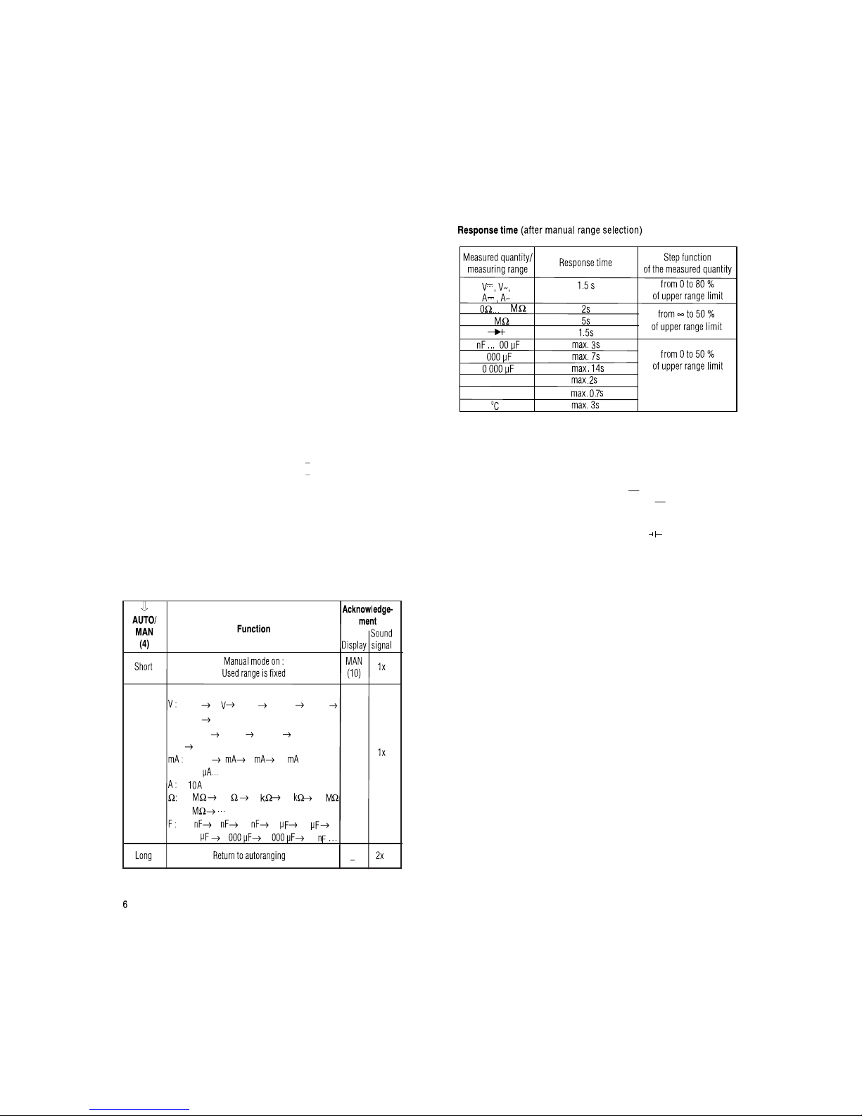
3. Function and range selection............................................................ 6
3.1. Auto ranging...................................................................................... 6
3.2 Manual range selection..................................................................... 6
4. Triple Digital Display.......................................................................... 7
4.1 Backlit................................................................................................ 7
5. DATA “HOLD” facility.......................................................................... 8
6. Minimum and maximum value storage facility ................................. 9
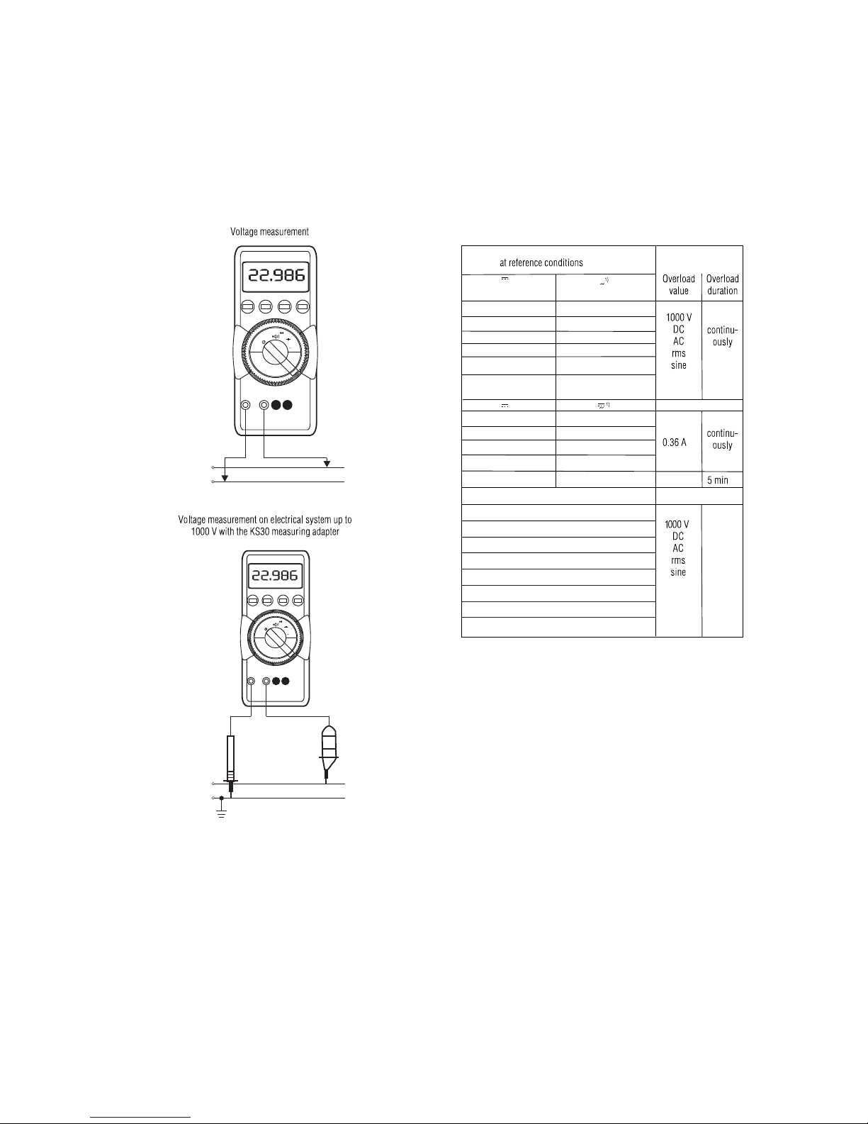
7. Voltage measurement........................................................................ 11
7.1 Voltage measurement on electrical systems up to 1000V
with the KS30 measuring adapter...................................................... 11
7.2 Simultaneous Frequency and A.C. Voltage measurement ................ 11
8. Current measurement........................................................................ 13
8.1 Simultaneous Frequency and AC current measurement .................. 13
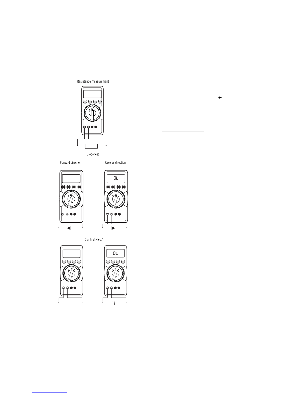
9. Resistance measurement and continuity test.................................... 15
10. Diode test .......................................................................................... 17
11. Capacitance measurement................................................................ 17
12. Frequency measurement................................................................... 18
13. Temperature measurement............................................................... 18
14. Stop watch......................................................................................... 19
15. Specifications.................................................................................... 20
16. Maintenance..................................................................................... 28
16.1 Battery............................................................................................... 28
16.2 Fuses................................................................................................ 28
16.3 Case................................................................................................. 29
17. Repair and replacement parts service.............................................. 29
18. Appendix........................................................................................... 29

29
4
1. Safety features and safety precautions
You have chosen a meter which offers you a very high degree of safety.
This meter Gamma 20 is manufactured and tested in compliance with the
safety standard IEC 61010-1:2001 / DIN EN61010 -1:2001.
In case of incorrect use or careless handling, the safety of both user and
multimeter is not assured.
To maintain the safe and proper condition of the meter and to ensure their safe
operation, it is absolutely necessary to carefully and completely read these
operating instructions before using any meter. These instructions must be
followed in all respects.
For your safety and for protection of the meter, this meter is fitted with an
Automatic terminal Blocking System It is coupled with the function selector
switch which blocks the terminal sockets not necessary for measurement.
Please note the following safety precautions:
lThe meter must be operated only by persons who understand the
danger of shock hazards and know how to apply safety precautions.
Shock hazards exist wherever voltages of more than 30V (TRMS) can
appear.
lDo not work alone in shock hazardous environment while carrying out
measurement.
lThe maximum permissible voltage between terminal Socket (7) and
ground is 1000 V.
lTake into account that unexpected voltages can occur on device under
test (e.g. defective instrument). Capacitors may be charged to a
dangerously high voltage, for instance.
lVerify that the test leads are in good condition, e.g. no cracked
insulation, no open circuits in the leads or connectors.
lThis meter must not be used for measurements on circuits with corona
discharge (high voltage).
lBe particularly careful when measuring on HF circuits. Dangerous
composite voltages may exist there.
lMeasurements under moist environmental conditions are not Permitted.
lDo not exceed the permissible overload limits of the measuring ranges.
See Table “Measuring ranges” under “15. Specifications”.
lAll current measuring ranges, are fused. The maximum permissible
voltage of the measuring circuit (=nominal voltage of the fuse) is1000 V
AC/DC in “mA” ranges, “A” ranges.
lYou must only use the meter in power systems, when the current circuit
is protected by a fuse or a circuit breaker of 20 A, and when the nominal
voltage of the system does not exceed 1000V.
For safe voltage measurements on power systems, up to 1000V we
recommend the KS 30 measuring adapter, which is available as accessory.
Its internal resistance limits the measuring current in the case of over voltage
and incorrect operation and safely suppress sparking from spark gaps. Also
refer to Section “7.1Voltage measurement on electrical systems up to 1000V
with the KS 30 measuring adapter”.
Fuse replacement
ŸOpen the meter same as for battery replacement
ŸRemove the blown fuse, e.g. with the aid of a probe, and replace it with a
new one.
Permissible types
Øfor current measuring ranges up to 300 mA:
FF (UR) 1.6A /1000 V AC/DC; (10 KA); 6.3 mm x 32 mm
Øfor the 10A current measuring ranges:
Type FF(UR) 16A/1000V AC/DC; (30kA); 10mmx38mm
Caution :
Absolutely verify that only the specified fuse is installed!
If a fuse of other cut-out capacity, other nominal current or other switching capacity
is used, a dangerous situation exists for you, and there is danger of damaging
protective diodes, resistors or other components.
The use of mended fuses or shorting of the fuse holder is not permissible.
16.3 Case
Special maintenance of the case is not required. Take care that the surface
between the connection sockets is clean. For cleaning take a moist cloth.
Avoid scrabbing.
17. Repair and replacement parts Service
When you need service, please contact :
Sifam Tinsley Instrumentation Ltd.
Central Buildings, Woodland Close,
Old Woods Trading Estate,
Torquey, Devan, England, TQ27BB
Website: www.sifamtinsley.com/uk
Contact Number: +44(O) 1803 615139
E-mail: info@tinsley.co.uk
Sifam Tinsley Instrumentation
3105, Creekside Village Drive,
Suite No 801,Kennesaw,
Georgia 30144
Contact Number: +1.404.736.4903
Web: www.sifamtinsley.com
18. Appendix
18.1 AC current measurement with (clip-on) current transformers
18.1.1 Transformer output mA/A
Caution:
If current transformers are operated with an open circuit on the secondary
side, e.g. due to defective or disconnected leads, a blown fuse In the meter, or
a wrong connection, dangerously high voltages can occur at the connectors.
Therefore, verify that the current circuit of the meter and the secondary
winding of the transformer connected to the meter form an intact circuit.
Connect the transformer to the sockets ^ and mA and/or A.
The maximum permissible operating voltage is the nominal voltage of the
current transformer. When reading the measured value, take into account the
transformer ratio and the additional error in indication.
18.1.2 Transformer output V
Several transformers are fitted with a voltage output (designation mV/A). The
secondary output must therefore be connected to the connection sockets ^
and V.

How to prevent automatic TURN-OFF
Switch your meter to "CONTINUOUSLY ON" mode.
ØTo do this, press y "ON/OFF"
pushbutton (2) together. The function "CONTINUOUSLY ON"
is shown on the LCD (1) by the symbol
ellow multi-function pushbutton (5) and the
(8).
ON
Automatic TURN - OFF
The meter turns off automatically, when the measured value remains constant
(variations of the measured value < + 2digits) for about 10 minutes and when
neither a pushbutton nor the function selector switch is operated during that
time.
Note:
Electric discharges and high-frequency interference may cause incorrect
information to be displayed and block the measuring process. Reset the meter
by switching it OFF and ON again otherwise, check the battery connections.
Disconnect the meter from the measuring circuit before you open it, and see
section "16.Maintenance"!
Repair, replacement of parts and calibration
When opening the meter, live parts may be exposed. Therefore, the meter
must be disconnected from the measuring circuit prior to opening its case
for repair or replacement of parts. If repair cannot be avoided unless the
meter is opened and live, this work must only be performed by a qualified
person who understands the danger involved.
Fausts and extraordinary stress
When it must be assumed that the safe operation is no longer possible,
take the meter out of service and secure it against accidental use.
It is assumed that safe operation may not be possible,
lwhen the meter shows obvious signs of damage,
lwhen the meter no longer functions correctly,
lafter prolonged storage under adverse conditions,
ldue to severe stress during transportation.
2. Switching the meter "ON”
Battery
Fit the meter with a 9V flat cell battery provided along with the meter.
Before you use the meter for the first time or after storage, refer to Section
"16.1 Maintenance-Battery".
Switching the meter "ON”
ØPress the "ON/OFF" pushbutton (2).
Switch-"ON" is acknowledged by a sound signal. As long as you keep
the pushbutton pressed, all segments of the liquid crystal display (LCD)
will appear. The LCD is shown on page 2.
After the pushbutton is released, the meter is ready for operation.
Meaning of the symbols on the device
Warning of a danger point
(Attention, refer to the usermanual)
Earth (ground) terminal.
Double or reinforced insulation
Instrument for over voltage
category II / III or IV
EU conformity mark.
CAT II / III / IV
28
Ambient conditions
Functional temperature
0
range -20
Storage temperature
0
range -25
Climatic class 2z/-20/50/70/75 % with ref
Altitude up to
Mechanical configuration
Protection type IP 50, for the connection sockets IP 20 according to
DIN VDE 0470 Part 1 /EN 60529
Dimensions 84 mm x
Weight 350 g approx.,including battery
16. Maintenance
Caution
Disconnect the meter from the measuring circuit before you open it to replace the
battery or the fuse!
16.1. Battery
Prior to initial start-up, or after storage of meter, verify that the batteries of
does not leak. Repeat this check in regular short intervals. If the battery leaks,
completely remove the battery electrolyte carefully with a moist cloth and install a
new battery before you operate again.
When the symbol " " (17) appears on the LCD (1) replace the battery as soon
as possible. You can continue to measure, but a reduced measuring accuracy
must be taken into account.
The meter operates with 9V flat cell battery according to IEC 6 F 22 or IEC6 Lr61 or
with a suitable NiCd storage battery.
0
C...+ 50 C
0
C...+ 70 C
erence to VDI/VDE 3540
2000 m
195 mm x 35 mm
meter
meter
Replacing the battery
ØPlace the meter on its face, loosen the two screws on the rear and remove
the lower part of the case, lifting it from the bottom. The lower and the upper
part of the case are fixed together at the top on the front by means of wedges.
ØRemove the battery from the compartment and carefully disconnect the
contacts from the battery.
ØSnap the connection contacts to a new 9V battery and insert the battery in to
the battery compartment.
ØReplace the lower part of the case. Start at the top on the front and take care
that the detent hooks are properly engaged at this point.
ØTighten the lower part with the two screws.
ØPlease destroy the batteries in an environment friendly way.
16.2 Fuses
A blown fuse is signalled on the LCD display the instant a measured quantity
having a voltage of more than 4 V is applied to the corresponding connection
sockets. Then, the digital display (9) shows "FUSE".
The 16 A fuse all other current measuring ranges. All other measuring ranges
continue to function. When a fuse blows, first eliminate the cause of the overload
using the meter again !
3.0V 30 300 V
1000 V
300mV
300uA 3 30 300
300
30 300 3.0 300 3.0
30
3.0 30 300
3.0
30
300 330 3.0
3.0V ...
Switching sequence at:
Hz: 300 Hz 3 KHz 30 KHz 300 KHz
300Hz ...
MAN
(10)
3.
The function selector switch (6) is coupled with the Automatic terminal
Blocking System which allows access only to two correct sockets for each
function. Prior to switching to the "mA" functions or from the "mA" or “A”
functions, remove the test lead from the corresponding socket. When the test
leads are plugged-in, the terminal blocking systems prevents accidental
switching to non permissible functions.
Function and range selection
3.1 Autoranging
The multimeters feature autoranging for all measuring ranges except for
temperature measurement and diode test. Autoranging is automatically
selected after switching the Multimeter ON. According to the measured
quantity applied, the multimeter automatically selects the measuring range
which gives the best resolution. When switching to frequency measurement
the previously selected voltage measuring range is maintained.
The meter switches automatically to :
The next higher range at + (309999 digits + 1digit)
the next lower range at + (28000 digits - 1 digit)
For capacitance measurement the change of
switchover occurs at (2999 digits + 1 digit)
and 280 digits-1 digit
Turning the multimeter OFF
ØPress the "ON/OFF" pushbutton (2).
3.2 Manual range selection
You can switch OFF auto-ranging and select the ranges manually according to
the table on the following page.
Manual mode is switched OFF when pushbutton AUTO/MAN is pressed (4) for
approximately 1s, when the function selector switch (6) is operated, or when
you turn the meter OFF and ON again.
27
30 3.0
30
3.0 3
3
3
300Hz,3KHz
30 KHz,300 KHz
Power supply
Battery 9V flat cell battery; manganese -dioxide cell according
to IEC 6 F 22, alkaline-manganese cell according to
IEC 6 LR 61 or suitable NiCd storage battery
Lifespan Without Backlit, using alkaline-manganese cell:
approx. 60 hours on V - - -
approx. 40 hours on V~, A~, A- - -
Battery test automatic display of the " " symbol, when the
battery voltage drops below approx. 6 V.
EMC Electromagnetic compatibility
Emission EN 61326 : 2002 Class B
Immunity EN 61326 : 2002
IEC 61000-4-2 8 kV atmosphere discharge
4 kV contact discharge
IEC 61000-4-3 : 3 V/m
Fuses
Fuse for the FF 1.6 A/1000 v: 6.3mmX32mm
ranges up to 300 mA rating 10 kA with 1000VAC/DC and ohmic load; in
conjunction with power diodes, protects all current
measuring ranges upto 300mA.
Fuse for the ranges upto rating 30 kA with 1000V AC/DC and ohmic load;
10A protects the 10 A ranges up to 1000 V AC/DC; see “16.
Maintenance” for manufacturers and types of fuses.

7
4.1 Backlit
The instrument is provided with user selectable Backlit for
measurements
in poor light conditions or dark area.
Switching the Backlit ON and OFF:
By pressing “AUTO/MAN” and “DATA/MIN/MAX” keys simultaneously
the Backlit can be switched ON.
And by pressing the same keys simultaneously Backlit can be switched
OFF.
Although the main display is activated immediately after the multimeter is
switched on, the two sub-displays must be activated with the MIN/MAX
key. This prevents the contineous display of an undefined condition which
was present at the start of measurement, e.g. open-circuit, as a maxi-
mum value.
The three digital displays, one main display and two sub-displays, show the
measurement value with correct decimal point and sign. The selected unit of
measure and the current type are also displayed. A minus sign appears in
front of the number for the measurement of zero-frequency direct quantities,
if the positive pole of the measured quantity is applied to perpendicular input.
“OL” (overload) is displayed, if the actual value falls above the measuring
range upper limit for the following measured quantities: VDC, IDC,
VAC,IAC,mAAC,mADC,F ‘Ω’,Hz:.
Refreshing of the digital display occurs at different intervals for the various
measured quantities ..
4. Triple Digital Display
Sub-Display:
MIN
Sub-Display:
MAX
Main Dis play
0 I5.000
0I3000 0 0I8000
MIN MAX V
DC
MAN
26
3.0 30
15 Digits
30 Digits
20 Digits
40 Digits
40 Digits
50 Digits
10 Digits
40 Digits
2Digits
2 Digits
1 Digit
1 Digit
m
1 Digit
V AC/DC
A AC/DC
300
30.0
300
> 50dB

25
300
300 300
300
3.0 3.0
30
3.0 30.0
30.0
300
...300 mA
30.0
0.5+3
0.3+3
0.2+3
0.2+3
0.05+3
0.1+5
0.1+3
0.6+3
0.5+3
2.0+3
0.1+3
1.0+20
1.0+20
1.0+20
2.5+20
1.0+20
0.5+20
2.0+20
1.0+20
1.0+20
1% of rdg
3% of rdg
+
-
+
-
0.5+2
8
Measurement values can be automatically “frozen” with the data function.
This can be especially useful when your full attention is required for testing
the measuring point with the test probes.
After the measurement value has been acquired, and the appropriate
“condition” has been fulfilled according to the following table, the
measurement value is displayed in the left hand sub-display and two acoustic
signal sounds. At the same time “MAN” appears and indicates that the
measuring range is now set. The test probes can now be removed from the
measuring point and the measurement value can be read from the sub-
display. If the measurement value lies below the limit value shown in the
table, the instrument is reactivated for the storage of a new value; the “HOLD”
display blinks.
5.DATA “HOLD” facility.
1X
>280000
<0L
>28000
short Flashes
>280000
<0L
>28000 Flashes
Acoustic Signal
DATA
V
DC
MAN HOLD
0 I5.000
0 I5.000
V
0 I5.000
DCHOLD

9
6. Minimum and Maximum Value Storage facility.
Minimum and maximum values can be read out at the sub displays for long-term
observation of measured quantities.
1.If the DATA/MIN/MAX key is activated twice, current MIN and MAX values are
displayed at the sub-displays.
2.Press the DATA/MIN/MAX key again to display the MIN value and the time of
occurrence.
3. If the DATA/MIN/MAX key is once again activated, the MAX value and the
corresponding time of occurrence are displayed.
MIN and MAX values are deleted by pressing and holding the DATA/MIN/MAX key
(approx. 1 s), by activating the rotary switch or by switching the instrument off and
back on again.
1) Reactivate by falling below the specified limits of the measured value.
2) When storing a value for the first time twice sound signal is generated.
For following “Holds” only twice if actual hold value differs from first
stored value by less than 100 digits.
The analog indication is not influenced by data HOLD. You can still read the
actual measured value. Note that with a “held” digital display, the location of
the decimal point is also held.
As long as the data HOLD function is active manual range selection is not
possible.
The data HOLD function is switched off, when the “DATA” push button (3) is
pressed for approximately 1 s, when the function selector switch (6) is
operated, or when meter is turned OFF and ON again.
Current
measurement
value
M i n &
M a x
1.
Activate,
and display
store
1x
24
Reference conditions
quantity
quantity sinusoidal
Ambient + 23
Relative humidity : 45% ... 55 % RH
Frequency of measured 45Hz ...65 Hz
Waveform of the measured
Battery voltage 8V ± 0.1V
0
temperature : C ± 2K
Display
Liquid crystal display section (65 mm x 30 mm) with analog indication and digital
display and with display of the unit of measured quantity, function and various
special functions.
Digital:
Display/Height of numer. 7-segment numerals/12mm
¾
Number of digits 5 digit Ù 31000 counts
Over range "OL" is displayed.
Polarity indication “-”sign is displayed, when the positive pole is at " ^ "
Sampling rate 10 reading/s

23
8) Without sensor.
7) Vac >1V eff/rms
10 Sec
< kHz
1000V
< 30kHz
300V
< 100kHz
30V
(...% of rdg+...% of rng)
(...% of rdg+ Digits)
10 Sec
8)
1Kelvin +3
8)
1Kelvin +3
8)
1% + 3
8)
1% + 3
+ 20 Digits 1000V
Contin-
uous
Contin-
uous
3)
2.5+0.2
1.2+0.2
1.2+0.2
1.2+0.2
1.2+0.2
3.2+1.0
3.2+1.0
3.2+1.0
7)
0.1+3
7)
0.1+3
7)
0.05+3
7)
0.05+3
10
Acoustic Signal
Acoustic Signal
V
DC
0 I5.345
V
0 I5.000
DC
V
DC
0 I5.I23
DATA
0 I5.345 0 I5.345
MIN MAX
MIN MAX
Current Meas. Value
Current
Meas. Value
Current
Meas. Value
DATA
MIN/MAX
short
DATA
MIN/MAX
short
DATA
MIN/MAX
long
DATA
MIN/MAX

22
0 0
2) At 0 c...+40 c.
3) With zero adjustment.
6) Lowest measurable frequency with a sinusoidal measuring signal which
is symmetrical to zero.
300.00 Hz
3.0000 kHz
30.000 kHz
-200.0
100.0
100.0...
0
+850.0 C
-100.0..
100.0
100.0..
850.0
0.1
0.1
0.1
0.1
300.00 kHz
3.0 3
30
300
3.0
30
300
3
3
3
3
3
3
3
3
3
3
100 Hz
100 Hz
2)
100 min 10 ms
10 MO
10 MO
1 MO
100 MO
11 kO
2 kO
2 kO
2 kO
0.01 Hz
0.1 Hz
1 Hz
10 Hz
10 Hz
11
7.2 Simultaneous Frequency and AC Voltage measurement:
Set the function selector switch to “ V~ ”
Briefly press the yellow multi-function pushbutton(s).
Now meter measures frequency on main display and Voltage on sub
display. Frequencies up to 40 KHz can be measured with this mode, but
voltage is measured accurately up to 20 KHz (See “ Influence quantities and
variations” on page 25)
To Exit this mode press yellow multi-function push button for long time.
This is acknowledged by the buzzer sounding twice.
Caution :
Ensure current measuring range (“mA’’ or “A”) is not selected, when you
connect your meter for When the cut-out rating of the
fuses is exceeded because of incorrect operation a dangerous situation
exists!.
voltage measurement!
7. Voltage measurement
ØConnect the test leads as shown. The “ ^ connected
to the lowest potential ground available.
’’ socket should be
Notes :
On the 1000 V range, an intermittent sound signal warns you, when the measured
value exceeds the upper range limit.
7.1 Voltage measurement on electrical systems up to 1000V
with the KS30 measuring adapter.
On low-Voltage systems, transient over voltages of several kilovolts can occur
due to switching functions or lightning discharges. Direct connection of your
meter to such systems for voltage measurement can be dangerous. For
voltage measurements in power systems with nominal voltages upto 1000V,
use the KS30 measuring adapter. It is an adapter for which eliminates
dangers caused by overvoltages and incorrect operation of the It
provides the following protective functions..
meter
meter.
—Protection of the input circuit of voltage measuring range of multimeters.
The internal resistance of the KS30 limits the current in the case of
overvoltage.
—Overload capacity : contin
Transient (rise 10 µ
—Safe suppression of sparking from spark plug after overvoltage.
—Current limitation in the case of incorrect operation (e.g. applying a
voltage to a current input)
Using the measuring adapter KS 30 the additional measured fault is approx .
-2%. Voltages above 1000 V can be measured with a high voltage probe,
provided the necessary safety precautions are taken!
uously 1000 Vrms
s/fall 1000 µs) 6 kV max.
21
3) With zero adjustment.
4) Display: 5¾ places for DC, 4¾ places for AC.
5) 12A 5min, 16A 30s.
6) Values less than 350 digits will be suppressed.
(...% of rdg+...% of rng
+...Digits)
(...% of rdg+...% of rng +...Digits)
(% of rdg+...Digits)
0.02+0.008+20
0.02+0.008+20
0.02+0.008+20
0.02+0.008+20
0.5+30
0.2+30
0.2+30
0.2+30
0.2+30
Intrinsic error of digital display
0.05+0.02+20
0.02+0.01+20
0.02+0.01+20
0.1+0.01+20
0.2+0.05+30
0.5+30
0.5+30
0.5+30
0.5+30
0.5+30
3)
0.05+0.015+20
0.05+0.015+20
0.05+0.015+20
0.05+0.025+20
0.1+0.025+20
0.1+0.25+20
0.2+0.0+10
6)
0.02+0.15+30
2)
Overload Capacity
5)
10A
1.2+0+10
10 sec.
12
+ ( - ) / ~
- ( + ) / ~
+ / ~
- / ~
F
W
Hz
V
---
V~ mA
---
0C
---
A
F
W
Hz
V
---
V~ mA
---
0C
---
A

20
15
1) TRMS measurement.
Values <150 Digit (350 Digit for measuring range 300 mV will be
suppressed.
0 0
2) At 0 c...+40 c.
Resolution at measuring
Range upper limit
4)
300000 4)
30000
300
3.0
30 1mV
300
1000 100mV
20M 5
5
5
5
5
5
300
3
30
300
10
10 nA
10 A
300 mV
300 mV
300 mV
300 mV
300
300mV
300
400mV
300 Ω
3.0 kΩ
30 kΩ1
300 kΩ
3.0 MΩ
30 MΩ1000
Open Circuit Voltage
0.6V
0.6V
0.6V
0.6V
0.6V
0.6V
300 Ω
100uV
Measurement
10 V 10 V
1mV
10mV
100mV
100 V 100 V
10 nA
100 nA 100 nA
1 A
400mV
Voltage drop. approx.
10m
100m
10
100
3.0 V
1000
0.1 Max. 1.3V
Max. 2.5V
13
8.1 Simultaneous Frequency and AC current measurement:
When in AC current measurement (mA or A), briefly press yellow
multifunction push button(s).
Now meter measures frequency on main display and AC current on sub
display. Frequencies up to 40 KHz can be measured, but current is
measured accurately up to 1 KHz.
To exit this mode press yellow multi-function push-button(s”) for long
time. This is acknowledged by the buzzer sounding twice.
9. Current Measurement
EFirst disconnect the power supply to the circuit being measured and/
or to the load, and discharge all capacitors within that circuit.
ESelect the DC current measuring ranges as described in section4.1
EWith the function selector
current of unknown magnitude,
ESelect the function corresponding to the measured quantity by briefly
pressing the yellow multi-function pushbutton (5). Each time the
pushbutton is pressed, alternate switching takes place between DC
and (DC + AC).
The change-over is acknowledged by a sound DC and
AC (11) are displayed as per selected function on the LCD. When selecting a
range with the function selector switch (6), the DC+AC function is always set
by default. When pressing the yellow multi- function pushbutton (5) for a long
time, the multimeter always switches back to DC + AC and acknowledges this
by two sound signals.
EConnect the multimeter in series with the load, as shown. Ensure
that the connections are tight (without contact resistance).
mA for currents <300 mA. When
measuring
- - -
select the highest
measuring range first.
signal. The symbols
Notes on Current measurement :
lThe multimeter must be used only in the power systems, where the
current circuit is protected by a fuse or a circuit breaker of 20 A and when
the nominal voltage of the system does not exceed1000V.
lMake the measuring circuit connections mechanically strong and secure
so that they do not accidentally open. The conductor cross sections and
connection points should be designed to avoid excessive heating.
lOn the 300 mA and 10 mA ranges, an Intermittent sound signal warns
you, when the Measured value exceeds the upper range limit.
lThe current measuring ranges upto 300 mA are protected to a short
circuit current of 25 A by a fuse 1.6 A/1000V AC/DC in conjunction, with
power diodes. The cut-out capacity of the fuse is 10kA at a rated voltage
of1000V AC/DC and ohmic load.
lThe current measuring ranges up to 10A are protected by a16A/1000V
fuse. The cut-out capacity of the fuse is 30kA at a nom. voltage of
1000V and ohmic load.
lA blown fuse is signalled on the LCD the instant a measured quantity
having a voltage of more than 4 V is applied to the corresponding
connection sockets. Then, the digital display (9) shows the word " FUSE"
lAfter a fuse has blown, eliminate the cause of the overload before using
the meter again !
lReplacement of the fuses is described in section ’’ 16. Maintenance’’.

14
+ ( - ) / ~
- ( + ) / ~
210.58mA
300
+ ( - ) / ~
- ( + ) / ~
10.000A
F
W
Hz
V
---
V~ mA
---
0C
---
A
~
~
A (20.1.1)
mA (20.1.1)
V (20.1.2)
Transformer output
210.58mA
F
W
Hz
V
---
V~ mA
---
0C
---
A
F
W
Hz
V
---
V~ mA
---
0C
---
A
19
14. Stop watch
This function allows you to measure elapsed times up to one hour.
ØRun the function selector switch (6) to “V - - - ”
ØThe function stop watch cannot be activated in the range 300 mV- - -
ØBriefly press the yellow multifunction push button (5)
“00:00:00” and the stop watch symbol (17) are displayed on the LCD.
ØThe stop watch is started and stopped by pressing the “AUTO/MAN”
pushbutton(4). The display is ‘n’ minutes, seconds and tenth of
seconds..
ØThe Time can be cleared by pressing the ‘DATA-MIN/MAX’ push
button (3).
ØBriefly press the multi function push button (6) in order to return to
voltage measurement.
15
18
Lead resistence of sensors can be considered up to a value of 50 Ω as follows:
The temperature measurement range is now selected.
ØThe LCD now displays. the zero resistance value. So that you can recognize that
this is the resistance correction value on the temperature measuring range, the “
0C” character is simultaneously shown.
ØYou can set the line resistance correction value as follows:
Press the DATA-MIN/MAX pushbutton (3) to increment the value, or the
AUTO/MAN pushbutton (4) to decrement the value. Each time the
pushbutton is briefly pressed, the value changes by one digit. you pass
through fast, when you press the pushbutton longer.
ØBriefly press the yellow multi-function pushbutton (5) again.
The LCD displays the measured temperature in consideration of the
changed lead resistance.
ØEach following time the yellow multi-function pushbutton (5) is briefly
pressed, the display changes between measured temperature with
changed lead resistance and correction value of the lead resistance.
You can exit the function “temperature measurement with changed lead
resistance”.
Set the function selector switch (6) to Hz.
See section “15. Specification” for the lowest measurement
frequencies and minimum measurable voltage levels.
12.Frequency measurement.
four ranges
i.e. 300 Hz,3 KHz,30KHz,300 KHz.
9. Resistance measurement and continuity test
ØVerify that the device under test is electrically dead. External voltages
would falsify the measured results!
ØSet the function selector switch (6) to " Ω
connect the device under test as shown.
"
Ø
Zero adjustment on the measuring range 300Ω
When measuring small resistance values on the 300 Ω range, you can
eliminate the resistance of the leads and contact resistance by zero
adjustment.
ØConnect the test leads to the meter and join the free ends.
ØBriefly press the yellow multi-function pushbutton (5).
The meter acknowledges zero adjustment by a sound signal, the LCD
shows “ 000,00” resp. “0,0000” (+1 digit) and symbol “ZERO” (18) is
displayed. The resistance measured the instant the pushbutton is
pressed is used as reference value (max. 2000 digits). it is
automatically deducted from the values measured thereafter.
You can clear the zero adjustment
àby pressing the yellow multifunction pushbutton (5) for a long time,
clearance is acknowledged by the buzzer sounding twice,
àby switching the instrument off.
Continuity test with buzzer
With “buzzer” function activated, the meter issues a continuous sound signal
below 10.00 Ω range only.
ØTo switch buzzer ON:
Select range 30kΩ, 300kΩ, 3.0 MΩ through manual mode and briefly press
the yellow multi function key (5). The symbol (17) appears on the display
screen.
ØTo switch buzzer OFF:
Briefly press the yellow multi function key (5). The symbol (17) disappears
from the display screen.
13. Temperature measurement
WPt100 and Pt1000 temperature sensors you can measure temperatures on
the range from -
ØSet the function selector switch (6) to “
ØConnect the sensor to the two sockets for which access is allowed.
The meter automatically detects the connected sensor (Pt100 to Pt1000) and
shows the measured temper
ith
0 0
200 (- 100) C...+850 C
0C”
0
ature in C on the digital display.
0 0
Briefly press the AUTO/MAN key to switch to “ F” and back to “ C”.
Temperature measurement
considering sensor lead resistances up to 50 Ω
16
02.1058
-
+
F
W
Hz
V
---
V~ mA
---
0C
---
A
-
+
F
W
Hz
V
---
V~ mA
---
0C
---
A
-
+
F
W
Hz
V
---
V~ mA
---
0C
---
A
0.6000
-
+
F
W
Hz
V
---
V~ mA
---
0C
---
A
00000
-
+
F
W
Hz
V
---
V~ mA
---
0C
---
A
17
10. Diode test
ØVerify that the device under test is electrically dead. External voltages
would falsify the measured results!
ØSet the function selector switch (6) to "
Connect the device under test as shown.
Forward direction and/or short circuit:
The multimeter displays the forward voltage in Volts. As long as the voltage
drop does not exceed the maximum display value of 2.999V, you can also test
several series-connected elements or reference diodes with small reference
voltage.
Reverse direction or interruption:
The meter indicates overrange "OL”
"
Ø
Note:
Resistors and semiconductor junction in parallel with the diode falsify the
measured results!
11. Capacitance measurement
ØVerify that the device under test is electrically dead. External voltages
would falsify the measured results!
ØSet the function selector switch (6) to “F”
ØConnect the (discharged !) device under test to the “ ^ ” sockets
via test lead.
and “ F ’’
Note:
Connect polarised capacitors with the " __ " pole to the " ^ " socket.
Resistors and semiconductor junctions in parallel with the capacitor falsify the
measured results!
ØConnect the test leads to the meter without device under test.
ØBriefly press the yellow multi-function pushbutton (5).
The meter acknowledges zero adjustment by a sound signal, by
displaying "0,000" resp. “00,00” (+1digit) and the symbol “ZERO” (18)
on the LCD. The capacitance measured at the instant the pushbutton is
pressed is used as reference value (max.500digits). It is automatically
deduced from the values measured thereafter.
The zero adjustment can be cleared
ØBy pressing the yellow multi-function pushbutton (5) for a long time,
clearance is acknowledged by the two sound signal.
ØBy switching the meter off.
Zero adjustment on the 30 nF measuring ranges 3nF to 30nF
When measuring small capacitance values on the 3 nF and 30 nF range, you
can eliminate the internal capacitance of the leads can be eliminated by zero
adjustment.
Table of contents
Other Sifam Tinsley Multimeter manuals


