Sifam Tinsley Zeta 30 User manual
User Manual
Analog-Digital Multimeter with Insulation Resistance Measurement
Zeta 30
IC 2-60-006-00-00551/REV-A/10/2014
Printed in India, Subject to change without Notice
Sifam Tinsley Instrumentation Ltd.
Central Buildings, Woodland Close,
Old Woods Trading Estate,
Torquey, Devan, England, TQ27BB
Website: www.sifamtinsley.com/uk
Contact Number: +44(O) 1803 615139
E-mail: info@tinsley.co.uk
Sifam Tinsley Instrumentation
3105, Creekside Village Drive,
Suite No 801,Kennesaw,
Georgia 30144
Contact Number: +1.404.736.4903
Web: www.sifamtinsley.com
P R E C I S I O N I N S T R U M E N T A T I O N


(8) (9) (10) (11)
(12)
(16) (15) (14) (13)
(18)
(17)
(19)
VA
MIN
MAX
DC
AC
ON
-8.8.8.8
10
0 20 30
MAN DATA
KW MW
kHz %
0C mF
nF
mm
+
+
5
ON
(1)
(2)
(3)
(4)
(5)
(6)
V
DC AC
20.16
(7)
10
0 20 30
MAN MAX
VINSU
1
Icap
(Iea)
DATA
MIN / MAX OFF
Func
INSU
mA
1000V 300mA 1000V
fused
1000V CATII/600V CATIII
IEC 61010-1
INSU
INSU
TRMS MULTIMETER
INSULATION TESTER
AUTO
MAN
ON
(1) Liquid crystal display
(2) ON/OFF pushbutton
(3) Pushbutton for data hold
and MIN/MAX storage functions
(4) Pushbutton for manual range
selection
(5) Multi function pushbutton
(6) Function selector switch.
(7) Terminal sockets with automatic
blocking system.
(8)Symbol for’’CONTINUOUSLY ON"
(9)Display for digits, decimal point and
polarity.
(10) Display for manual range selection,
DATA hold and MIN/MAX storage.
(11) Display for the selected function
(12) Display for the unit of
measured quantity.
(13) Over range indication for
positive analog range.
(14) Pointer for analog indication.
(15) Scale for analog indication
(16) Over range indication for
negative analog range.
(17) Low battery indication.
(18) Buzzer indication
(19)
Display for temperature
0C
measurement range.

1
Contents Page
1. Introduction
...............................................................................
2.
Safety features and safety precautions..............................................
3. Switching the multimeter "ON"............................................................
4.
Function and range selection..............................................................
4.1 Switching the DC current measuring ranges........
.....................................
4.2 Autoranging
...............................................................................
4.3
Manual range selection.......................................................................
5
Liquid crystal display...........................................................................
5.1 Digital display
...............................................................................
5.2
Analog indication ................................................................................
6.
”DATA ” hold facility..............................................................................
7.
Minimum value and maximum value “MIN/MAX” storage facility
...............
8.
Voltage measurement.........................................................................
8.1 Voltage measurement on electrical system upto 1000V
with the KS30 measuring adapter........................................................
9.
Current measurement.........................................................................
9.1
AC current measurement with (clip-on) current transformers.....................
10.
Resistance measurement...................................................................
11.
Diode test and continuity test..............................................................
12.
Capacitance measurement ...............................................................
13. Frequency measurement ...................................................................
14. Duty cycle measurement ...................................................................
15. Temperature measurement ................................................................
16. Insulation resistance measurement ...................................................
18.1
Battery.................................................................................................
18.2
Fuses..................................................................................................
18.3
Case...................................................................................................
19 Servicing.............................................................................................
5.3
Backlit (optional) .................................................................................
16.1 Before measurement .........................................................................
16.2 Selecting Test Voltage .......................................................................
16.3 Insulation Resistance measurement .................................................
16.4 After Insulation measurement ...........................................................
17. Specifications
................................................................................
18. Maintenance
.................................................................................
16.5 Evaluation of measurement values ...................................................
2
2
3
4
4
4
5
5
5
5
6
6
6
7
9
9
11
11
13
14
15
15
16
17
17
17
17
18
18
19
27
27
28
28
28
INDEX

2
1. Introduction:
Thank you very much for selecting our multimeter. We are the leading
manufacturer of Electrical and Electronics measuring instruments. These
multimeters are manufactured as per IS 13875 and DIN 43751.
2. Safety features and safety precautions
You have chosen a multimeter which provides you a very high degree of
safety. This meter is manufactured and tested in compliance with the safety
standard IEC 61010-1:2001/ DIN EN61010 -1:2001 and IEC61557.
In case of incorrect use or careless handling, the safety of both user and
multimeter is not assured.
For proper use and safe handling, it is absolutely necessary to read and
understand the operating instructions before using the meter.
For your safety and for protection of the multimeter, this meter is fitted with an
Automatic terminal Blocking System (ABS).
It is coupled with the function selector switch which blocks the Terminal
sockets not necessary for measurement.
Please note the following safety precautions:
lThe multimeter must be operated only by persons who understand the
danger of shock hazards and are aware of the necessary safety
precautions. Shock hazards exist wherever voltages of more than 30V
(TRMS) are present.
lDo not work alone in shock hazardous environment while carrying out
measurement.
lThe maximum permissible voltage between terminal Socket (7) and
ground is 1000 V.
lTake into account that unexpected voltages can occur on device under
test (e.g. defective instrument). For example, capacitors may be
charged to a dangerously high voltage.
lVerify that the test leads are in good condition, e.g.no cracked insulation,
no open circuits in the leads or connectors.
lThis multimeter must not be used for measurements on circuits with
corona discharge (high voltage).
lBe particularly careful when measuring on HF circuits. Dangerous
composite voltages may exist there.
lMeasurements under moist environmental conditions are not Permitted.
lDo not overload the measuring ranges beyond their allowable
capacities. Limit values are given in specifications Refer Chapter 17.
lAll current measuring ranges, are protected with fuse. The maximum
permissible voltage of the measuring circuit (=nominal voltage of the
fuse) is1000 VAC/DC in “mA” ranges.
WARRANTY
Dear Customer,
You are now the privileged owner of Zeta 30 Analog-Digital / Multimeter a
product that ranks the first of its kind in the world. Company provides 12
months warranty from the original date of Purchase against defective
material and workmanship.
In the unlikely event of failure of the instrument / accessories within the
warranty period. Company will repair meter / accessories free of charge.
Please hand over the meter / accessories to the dealer / stockist from whom
you have purchased along with this card and relevant Cash Memo / Invoice.
This warranty entitles you to bring the meter / accessories at your cost to the
nearest stockist / dealer and collect it after repairs.
NO TRANSPORTATION CHARGES WILL BE REIMBURSED.
The warranty is not valid in following cases:
1. Warranty card duly signed and stamped and original Cash Memo / Invoice
is not sent along with Meter.
2. Complete warranty card is not presented to authorised person at the time
of repairs.
3. Meter / accessories is not used as per the instructions in the instruction
manual.
4. Defect caused by misuse, negligence, accidents, tampering and Acts of
God.
5. Improper repairing by any person not authorised by the company.
6. Modification, Alteration of any sort is made in electrical circuitry.
7. Seal provided inside/outside is broken.
Warranty of Zeta 20 accessories does not cover Fuses, Battery & Mains
Adapter.
In case of dispute to the validity of the warranty, the decision of Company
service center will be final.
If you bought this Meter directly from the company, and if you notice transit
damage, then you must obtain the insurance surveyors report and forward it
to Company .
Thank you.
(To be filled by authorized dealer)
Model No. :
Serial No. :
Date of Purchase :
Cash Memo / Invoice No. :
Dealer’s Signature :
Dealer’s Stamp :
Scope of Supply
1) Instrument 2) Cable Set
3) Spare Fuse 4) Safety Cover
5) 1.5 V Battery 6 Nos. - Rechargeable - Yes No
6) User Manual 7) Warranty Card
8) Crocodile Clips 9) Belt

3
Note:
Electric discharges and high-frequency influence may cause incorrect
information to be displayed and block the measuring process. Reset the meter
by switching it OFF and ON again otherwise, check the battery connections.
Repair, replacement of parts:
When opening the meter, live parts may be exposed. Therefore, the meter
must be disconnected from the measuring circuit prior to opening its case for
repair or replacement of parts. If repair cannot be avoided unless the meter is
opened and live, this work must only be performed by a qualified person who
understands the danger involved.
When it is realised that the safe operation is no longer possible, take the meter
out of service and secure it against accidental use.
Safe operation may not be possible,
lwhen the meter shows obvious signs of damage,
lwhen the meter no longer functions correctly,
lafter prolonged storage under adverse conditions,
ldue to severe stress during transportation.
3. Switching the multimeter "ON”
Battery
We have already fitted your meter with a 1.5V x 6 (AAA size)batteries
according to IEC 6 LR 03. It is ready for operation.
for the first time or after storage, refer to Section "18.1 Maintenance-Battery".
Before you use the meter
Switching the meter "ON”
Press the "ON/OFF" pushbutton (2).
Switch-"ON" is acknowledged by a sound signal. As long as you keep
the pushbutton pressed, all segments of the liquid crystal display (LCD)
will appear. The LCD is shown on page before 1.
After the pushbutton is released, the meter is ready for operation.
l
lFor safe transient voltage measurements in power systems upto
1000V, we recommend the KS30 measuring adapter, which is
available as an accessory. Its internal resistance limits the
measuring current in the case of over voltage, in correct operation
and safely suppresses sparking from spark gap. Also refer to
Section “8.1 Voltage measurement” on electrical systems up to
1000V with KS30 measuring adapter.
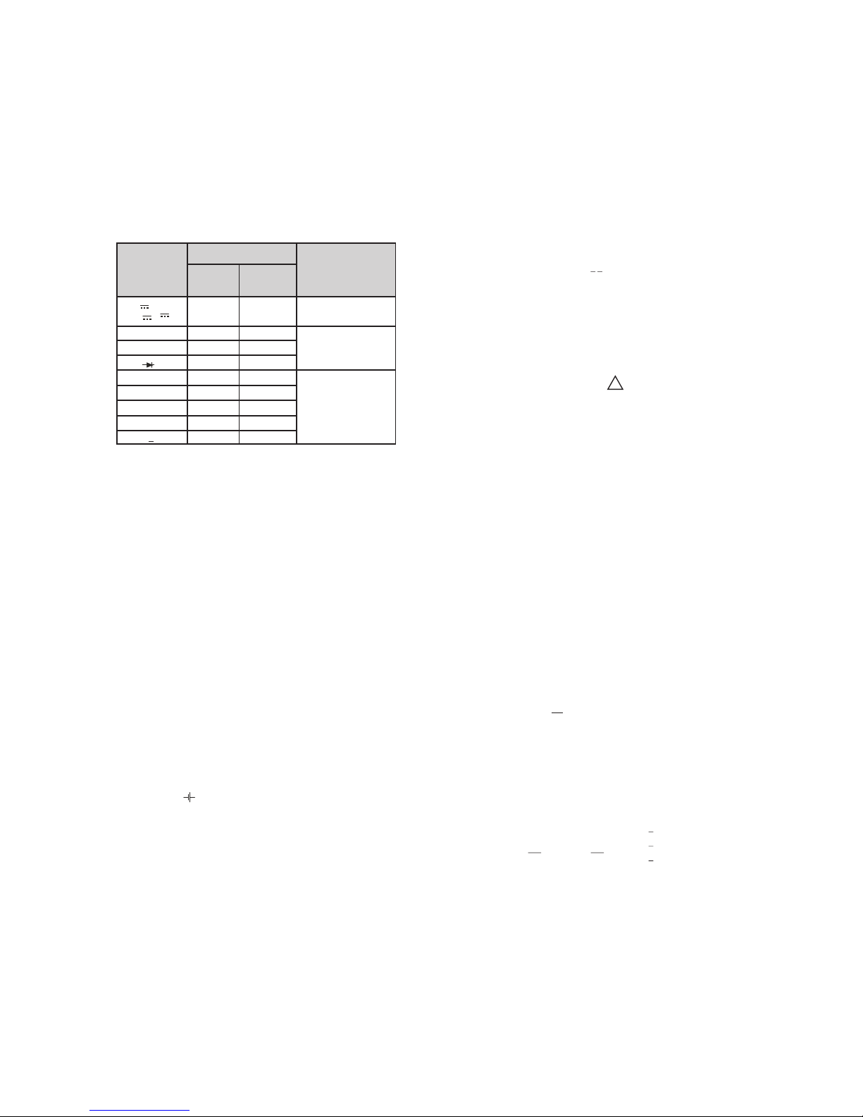
Meaning of the symbols on the device
Warning of a danger point
(Attention, refer to the user manual)
Earth (ground) terminal.
Double or reinforced insulation
Instrument for over voltage
category II / III or IV
EU conformity mark.
CAT II / III / IV
28
19. Servicing
When you need service, please contact :
Replacing the battery
ŸPlace the multimeter on its face, loosen the two screws on the rear and
remove the lower part of the case, lifting it from the bottom. The lower and the
upper part of the case are fixed together at the top on the front by means of
wedges.
ŸRemove all six batteries from the battery holder.
ŸPlace six new batteries into battery holder with correct polarities.
ŸReplace the lower part of the case. Start at the top on the front and take care
that the wedges are properly engaged at this point.
ŸTighten the lower part with the two screws.
ŸPlease destroy the batteries in an environment friendly way.
18.2 Fuses
A blown fuse is signalled on the LCD display the instant a measured quantity
having a voltage of more than 4 V is applied to the corresponding connection
sockets.
Then, the digital display (9) shows "FUSE"
The 1.6 A protects all other current measuring ranges. All other measuring
ranges continue to function.
When a fuse blows, first eliminate the cause of the overload using the multimeter
again !
Fuse replacement
ŸOpen the multimeter same as for battery replacement
ŸRemove the blown fuse, e.g. with the aid of a probe, and replace it with a
new one.
ØPermissible types for current measuring ranges up to 300 mA:
FF (UR) 1.6 A / 1000 V AC/DC; (10 KA); 6.3 mm x 32 mm
Caution :
Absolutely verify that only the specified fuse is installed!
If a fuse of other cut-out capacity, other nominal current or other switching capacity
is used, a dangerous situation exists, and there is danger of damaging protective
diodes, resistors or other components.
The shorting of the fuse holder is not permissible.
18.3 Case
Special maintenance of the case is not required. Take care that the surface
between the connection sockets is clean. For cleaning take a moist cloth.
Avoid scrabbing.
Sifam Tinsley Instrumentation Ltd.
Central Buildings, Woodland Close,
Old Woods Trading Estate,
Torquey, Devan, England, TQ27BB
Website: www.sifamtinsley.com/uk
Contact Number: +44(O) 1803 615139
E-mail: info@tinsley.co.uk
Sifam Tinsley Instrumentation
3105, Creekside Village Drive,
Suite No 801,Kennesaw,
Georgia 30144
Contact Number: +1.404.736.4903
Web: www.sifamtinsley.com
The Information contained in these installation instructions is for use only by installers
trained to make electrical power installations and is intended to describe the correct method
of installation for this product.
It is the user's responsibility to determine the suitability of the installation method in the
user’s field conditions.
4
4.
The function selector switch (6) is coupled with the Automatic terminal
Blocking System (ABS) which allows access only to two correct sockets for
each function. Prior to switching to the "mA" functions or from the "mA"
functions, remove the test lead from the corresponding socket. When the test
leads are plugged-in, the terminal blocking systems prevents accidental
switching to non permissible functions.
Function and range selection
4.1 Switching the DC current measuring ranges
300 µ A, 30 mA,300 mA
not automatically selected when the meter is switched ON. The above ranges
can only be selected manually with “AUTO/MAN” key!
The current measuring ranges mentioned above are
Turning the multimeter OFF
Press the "ON/OFF" pushbutton (2).
How to prevent automatic TURN-OFF
In order to prevent automatic "TURN OFF" select "CONTINUOUSLY ON"
mode. For this, press y "ON/OFF"
pushbutton (2) together. The function "CONTINUOUSLY ON"
is shown on the LCD (1) by the symbol
ellow multi-function pushbutton (5) and the
(8).
ON
4.2 Autoranging
The multimeters feature autoranging for all measuring ranges with the
exception of the 30 mV
Autoranging is automatically selected after switching the Multimeter ON.
According to the measured quantity applied, the multimeter automatically
selects the measuring range which gives the best resolution. When switching
to frequency measurement and to ratio measurement, the previously selected
voltage measuring range is maintained.
- - -, 300 mV.
Note:
FAutomatic turn-OFF is inactive on all current measuring ranges when
the measured value display exceeds 30 digits.
Set the function selector switch (6) to the desired position.
Disconnect the meter from the measuring circuit before you open it, and see
section "18.Maintenance"!
Automatic TURN - OFF
The meter turns off automatically, when the measured value remains constant
(variations of the measured value < + 2digits) for about 10 minutes and when
neither a pushbutton nor the function selector switch is operated during that
time. It remains ON, however, when a current measuring range is selected and
a measured value>30digits is displayed.
The meter switches automatically to :
The next higher range at + (3099 digits + 1digit)
the next lower range at + (240/280 digits - 1 digit)
from the 300mA - - - to the 3mA - - - range at + (24 digits - 1 digit)
27
Response time Transient response for
step function of the
measured quantity
Response time (after manual range selection)
of analog
indication
V
,
V
~,
A
,
A
30W ... 3 MW
30 MW
nF mF,
0
C
300 Hz, 3 kHz
30, 100 kHz
% (1 Hz)
% ( >10Hz)
Measured quantity/
measuring range of digital
display
0.7 s
1.5 s
4s
0.7 s
1.5 s
2 s
5 s
1.5 s
max. 1...3 s
max. 2 s
max. 0.7 s
max. 9 s
max. 2.5 s
from 0 to 80 %
of upper range limit
from
oo to 50 %
of upper range limit
from 0 to 50 %
of upper range limit
~
Interface
Type RS232C, serial, as per DIN 19241
Data transmission Optically with infrared light through the case
Baud rate 8192 bits/s
Ambient conditions
Functional temperature
0
range -10
Storage temperature
0
range -25
Climatic class 2z/-10/50/70/75 % with ref
Altitude up to
Mechanical configuration
Protection type IP 50, for the connection sockets IP 20 according to
DIN VDE 0470 Part 1 /EN 60529
Dimensions 84 mm x
Weight 350 g approx.,including battery
18. Maintenance
Caution
Disconnect the meter from the measuring circuit before you open it to replace the
battery or the fuse!
18.1. Battery
Prior to initial start-up, or after storage of multimeter, verify that the batteries of
multimeter does not leak. Repeat this check in regular short intervals. If the battery
leaks, completely remove the battery electrolyte carefully with a moist cloth and
install a new battery before you operate multimeter again.
When the symbol " " (17) appears on the LCD (1) replace the battery as soon
as possible. Measurement can be done, but a reduced measuring accuracy must
be taken into account.
The multimeter operates with a 1.5 V x 6 batteries according to IEC6 LR03.
0
C...+ 50 C
0
C...+ 70 C without batteries
erence to VDI/VDE 3540
2000 m
195 mm x 35 mm

5
4.3 Manual range selection
You can switch OFF auto-ranging and select the ranges manually according to
the table on the following page.
Manual mode is switched OFF when pushbutton AUTO/MAN is pressed (4) for
approximately 1s, when the function selector switch (6) is operated, or when
the meter is turned OFF and ON again.
When switching back to auto-ranging from 30 mV - - - or 300 mV - - - ranges,
- - - range is automatically selected.
3 V
5. Liquid crystal display
5.1 Digital display
The digital display (9) shows the measured value with correct location of
decimal point
are simultaneously
appears in front of the digits, when the positive pole of the measured quantity is
applied to the " ^ ( on the
r
With V, A per
second.
and sign. The selected measuring Unit (12) and the function (11)
displayed. When measuring DC quantities, a minus sign
" input terminal. When upper range limit 3099
ange :1999), is exceeded then "OL" is displayed.
and Ω measurements, the digital display is updated two times
5.2 Analog indication
The analog indication with pointer presentation gives the dynamic response of
a moving-coil movement and is updated 20 times per second, when measuring
V, A and Ω. when observing
variations of measured values and for calibration procedures.
The analog indicator has its own polarity indication. When measuring DC
quantities, the analog scale (15) has a negative range of 5 scale divisions so
that variations of the measured values around "zero"can be observed exactly.
When the measured value exceeds the range of indication, the left triangle (16)
is shown before the polarity of the analog indicator switches over after
approximately 0.7s. The over range indication on the measuring range (>3099
digits, on the range by the right triangle (13).
Analog indication is of particular advantage
>1999) is shown
Manual mode on :
Used range is fixed 1 x
MAN
(10)
Short
Long Return to autoranging - 2 X
Icap
(Iea)
2.3mA 22.57mA 107.7mA 121.7mA 2.3mA
Switching sequence at:
V -: 3V 30V 300V 1000V 30mV
300mV 3V
1 x
MAN
(10)
Short
Hz: 300Hz 3kHz 30kHz 100kHz 300Hz
F: 30nF 300nF 3 F 30 F 30nF
V :3V 30V 300V 1000V 3V ...
mA -:300 A 3mA 30mA 300mA 300 A
mA : 3mA 300mA 3mA
30A 300A 30A...
30M 30 300 3 k 30 k
300 k 3 M 30M
AUTO/
MAN
(4)
Function
Acknowl-
edgement
Dis-
play Sound
Signal
26
Display
Liquid crystal display section (65 mm x 30 mm) with analog indication and digital
display and with display of the unit of measured quantity, function and various
special functions.
Analog :
Indication LCD scale with pointer
Scale length 55 mm on V and A , 47 mm on all other ranges
Graduation + 5...0...+
...30 with 30 scale divisions on all other ranges
Polarity indication with automatic change-over
Overrange indication by triangle (13)
Sampling rate 20
Digital:
Display/Height of numer. 7-segment numerals/15mm
¾
Number of digits 3
Over range "OL"is displayed.
Polarity indication “-”sign is displayed, when the positive pole is at " ^
Sampling rate 2
Power supply
Battery 1.5V X 6 (AAA size)
to IEC 6 LR 03.
Lifespan Without Backlit ON, using alkaline-manganese cell:
approx. 600 hours on Vdc , Adc
approx. 240 hours on Vac , Aac
approx. 800 measurements for MWINSU @ 1000V
approx. 2400 measurements, for MWINSU @ 50V,
100V, 250V,500V.
When operating with interface: times x 0.7
Battery test automatic display of the " " symbol, when the
battery voltage drops below approx. 7 V.
Electromagnetic compatibility
EN 61326 : 2002 Class B
EN 61326 : 2002
IEC 61000-4-2 8 kV atmosphere discharge
4 kV contact discharge
IEC 61000-4-3 : 3 V/m
Fuses
Fuse for upto 300mA ranges
FF (UR) 1.6 A / 1000V AC/DC; 6.3mm X 32mm; rating 10kA with 1000VAC/DC
and ohmic load; in conjuction with power diodes, protects all current measuring
ranges upto 300mA.
- - - - - -
30 with 35 scale divisions on - - -,
0
readings/s, on W ; 10 readings/s
digit Ù 3100 counts
"
0
reading/s, on W and C: 1 reading/s
alkaline-manganese cell
according
EMC
Emission
Immunity
6
7. Minimum value and Maximum value ’’MIN/MAX" storage
facility.
With the MIN/MAX function, you can hold the minimum and the maximum
measured value which was applied to the input of the multimeter after
activating MIN/MAX function. The most important application is the
determination of the minimum and the maximum value for long-term
monitoring of measured quantities. MIN/MAX does not influence the analog
indication The actual measured value can still be noted/read. Apply the
measured quantity to the meter and select the measuring range prior to
activating the MIN/MAX function. With the function activated, you can select
the measuring ranges only manually, if you switch to another range, the
stored MIN/MAX values are cleared.
1) Reactivated by falling below the specified limits of the measured value.
2) With the exception of the ranges 30 mV and 300 mV.
As long as the DATA hold function is active, manual range selection is not
possible. The DATA hold function is switched OFF, when,
EThe “
acknowledged by 2 sound signals.
EThe function selector switch (6) is operated or
EThe multimeter is turned OFF and ON again.
DATA ” push button(3) is pressed for approx. 1s. This is
5.3. Backlit
The instrument is provided with user selectable Back-lit for taking
measurements in poor lighting conditions/ dark areas.
Switching the Backlit ON
By pressing “AUTO/MAN” and “DATA/MIN/MAX” keys simultaneously the
Backlit can be switched ON.
Switching the Backlit OFF
By pressing “AUTO/MAN” and “DATA/MIN/MAX” keys simultaneously the
Backlit can be switched OFF.
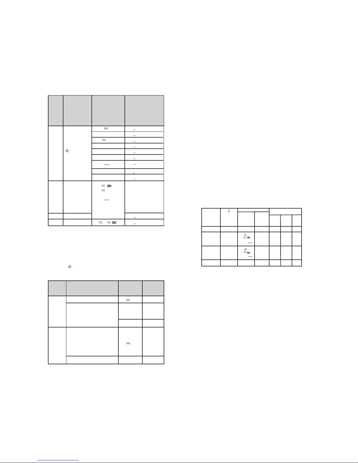
6. “DATA” hold facility
The DATA function allows to automatically hold the measured values. This is
particularly useful, for instance, when connecting the probes to the measuring
point requires full attention. When the measured value is applied and the
’’condition’’ according to the table shown below is met, the meter holds the
measured value on the digital display and emits a sound signal. The probes
can now be removed from the measuring point and the measured value on the
digital display (9) can be read. When the measured value falls below the limit
specified in the table, the meter is reactivated for a new storage.
The analog indication is not influenced by the DATA hold,
measured value can still be noted / read. Note that with a held digital display,
the location of the decimal point is also held. With autoranging selected, the
measuring range of the analog indicator is no longer known.
The actual
Function
DATA
Activate
Store
Reactive
1)
Reset
Short
Long
DATA
MIN/MAX
(3)
Condition
Measuring
Ranges
>280
>24
< OL
>280
< 280
< 24
OL
< 280
dis-
played
stored
mea-
sured
value
Cleared
flashes
dis-
played
flashes
Cleared
1 x
1 x
2 x
Meteracknowledgement
Display
DATA
Sound
Signal
Meas.
Value
digital
Limit of
Measured
Values
(digits)
V
2)
A
Ω,
F,Hz,%,
Icap
(Iea)
V
2)
A
Ω,
F,Hz,%,
Icap
(Iea)
25
Influence
quantity Range of Influence Measuring
ranges Attenuation
Common
mode
interference
voltage
Normal
mode
interference
voltage
V> 120 dB
3V~ , 30 V ~
> 70 dB
300 V ~
1000 V ~ > 60 dB
V> 50 dB
V
~
> 110 dB
Noise quantity max. 1000 V ~
Noise quantity max. 1000 V ~
50 Hz, 60 Hz sinusoidal
Noise quantity V ~
value of the measuring range at at ime
max. 1000 V ~ , 50 Hz, 60 Hz.
sinusoidal
Noise quantity max. 1000 V -
Variation
Influence
quantity
Range of Influence
Measured
quantity/
Measuring range
+ 1 Digit
+ 2 Digit
1 x intrinsic error
V + 2 Digit
V~ + 4 Digit
A
+ 4 Digit
A~ + 6 Digit
30Ω / 300 /Ω
0
C + 4 Digit
3 kΩ --- 30 MΩ+ 3 Digit
nF, mF, + 1 Digit
Hz + 1 Digit
%+ 1 Digit
5)
...< 7.9 V
> 8.1 V ...10.0V
75 %
3 days
Meter off
-
-
Battery
voltage
Relative
humidity
DATA
MIN/MAX
V
A
Ω
F,
Hz
%
0
C
V, A
Icap
(Iea)
Icap
(Iea)
V,
,
,M INSUΩ
1) With Temperature : Error for data apply per 10 K change in temperature
With Frequency : Error data apply to a display from 300 digits onwards
2) With zero adjustment
3) With unknown waveform (crest factor CF > 2), measure with manual range
selection
4) With exception of sinusoidal waveform.
5) After the “ ” symbol is displayed.
7
Function
MIN/MAX
2 x Short,
30 mV/
300 mV
and 0C
1 x short
short
short
Short
Long
DATA
MIN/MAX
(3)
Measured
Values
MINandMAX
Stored
Storage Continued
in the background,
new MIN / MAX.
values are displayed
Same as 1.,
Stored Values are
not cleared
Cleared
actual
meas-
ured
value
stored
MIN
value
stored
MAX
value
same
as 1.
Cleared
MIN
and
MAX
flash
MIN
MAX
same
as 1.
Cleared
Meter acknowledgement
Display
MIN
MAX
Meas-
uring
ranges
Sound
Signal
1.
Activate and
Store
2.
Store and
display
3.
Return to 1.
Reset
1 x
1 x
1 x
1 x
2 x
Meas.
Value
digital
V
A
Ω
F,Hz,%
0C
V
A
Ω
F,Hz,%
0C
Same
as 1.
Icap
(Iea)
Icap
(Iea)
The MIN/MAX function is switched OFF, when the MIN/MAX pushbutton (3) is
pressed for approximately 1s, or when the function selector switch (6) is
operated, or when the meter is turned OFF and ON again.
Notes :
The 30 mV
with the ’’ AUTO/MAN ’’ pushbutton (4) !
On the 1000 V measured
value exceeds the upper range limit.
- - - and 300 mV - - - measuring ranges can only be selected
range, an intermittent sound signal warns you, when the
manually
Caution :
Ensure current measuring range (“mA’’) is not selected
When the cut-out rating of the fuses is exceeded because of
incorrect operation A dangerous situation exists!.
for voltage
measurement
Zero adjustment on the 30 mV
EConnect the test leads to the meter and join the free ends. After having
selected the measuring range, briefly press the yellow multi- function
pushbutton (5).
The meter acknowledges zero setting by a sound signal, the LCD shows
“00.00’’ (+ 1 digit) and the decimal point flashes. The displayed voltage at the
instant the pushbutton is pressed, is used as reference value (max
thereafter.
The zero adjustment is cleared when ;
EBy pressing the yellow multifunction pushbutton (5) for a long time,
clearance is acknowledged by the two sound signal.
EBy switching the instrument OFF.
- - - measuring range
+ 200
digits) it is automatically deducted from the values measured
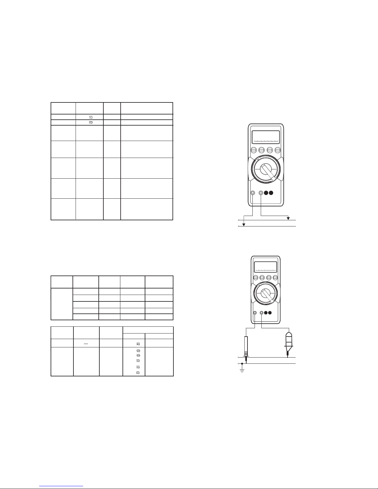
8. Voltage measurement
EAccording to the voltage to be measured , set the function selector
switch (6) to V
EConnect the test leads as shown. The “ ^ connected
to the lowest potential ground available.
~, V - - - or V - - -
’’ socket should be
24
Influence Quantities and Variations
Influence
quantity
RangeofInfluence
Measured
quantity/
Measuring range
Variation
1)
+ (...% of rdg. + ... digits)
Temperature
+ 21
0C
and
+ 25
0 0
C... + 40 C
30/300 mV 1.0 + 3
3... 300 V 0.15 + 1
1000 V 0.2 + 1
V ~0.4 + 2
300
m
A
2)
... 0.5 + 1
300 mA
A 0.75 + 3
30
Ω
0.15 + 2
300
Ω
0.25 + 2
3K
W -
3M
Ω
0.15 + 1
30 M
Ω
1.0 + 1
30 nF - 3
m
F
30
m
F
Hz
% + 5 Digit
-
200 ... + 200 0C
+ 200 ... + 850 0C
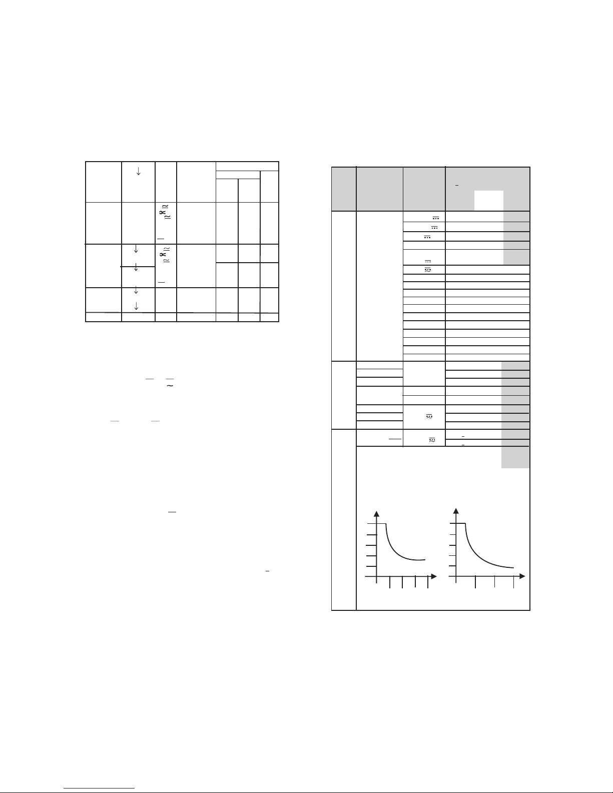
Voltage measurement Current measurement
0 500 V 1000V
CF
5
4
3
2
1
0
0 1000 2000 3000
CF
5
4
3
2
1
0
The permissible crest factor CF of the AC quantity to be measured is a function of the
displayed value :
measured
Wave form
of the
3)
quantity
2)
2) 0.5 + 2
2.0 + 2
0.5 + 1
-
0.5K+2
0.5+2
M INSUΩ
0.25+2
0
0 C
Frequency
of the
measured
quantity
15 Hz ... < 30 Hz
30 Hz... < 45 Hz
> 65 Hz... 400 Hz
400 Hz... 1 kHz 3 ... 300 V ~
1.0 + 3
0.5 + 3
2.0 + 3
3.0 + 3
15 Hz... < 30 Hz
30 Hz ... < 45 Hz
> 65 Hz... 1 kHz
A
1.0 + 3
0.5 + 3
3.0 + 3
Crest. 1... 3
factor CF > 3...5 V ~
4)
, A
4)
+ 1 % of rdg.
+ 3 % of rdg.
1000 V ~
3.0 + 7
3 ... 1000 V ~
8
Voltage measurement
Voltage measurement on electrical systems upto 1000V
with the KS30 measuring adapter
22.98
+(-)/~
-(+)/~
+/~
-/~
22.98
23
Short-Circuit current
Measurement Nominal Voltage Open circuit
Function Voltage V0
Nominal Current
MWINSU
50V
100V
250V
500V
1000V
<1.15xU N>1.0 mA < 2.5 mA
<1.15xU N>1.0 mA < 2.5 mA
<1.15xU N>1.0 mA < 2.5 mA
<1.25xU N>1.0 mA < 2.5 mA
<1.25xU N>1.0 mA < 2.5 mA
U
N
1000V
Duration
Measurement Nominal Voltage Acoustic Signal
Value
MWINSU
Function
R <2MΩ
X
V
N
Overload capacity
1000V
500V
250V
100V
50V
R <1MΩ
X
R <0.5MΩ
X
R <0.2MΩ
X
R <0.1MΩ
X
V1MW V
N
V
>1000V
Continuous
1000V
1000V
1000V
1000V
1000V
1000V
max.10S
Insulation resistance measurement
Measurement
Function Measuring Range
Resolution Intrensic error of digital display
(%rdg+digits) at reference conditions.
V1MW0...1000V 1V 1+10
MWINSU@1000V 0...1000V 1V 1+10
0.100... 1.600 MΩ
01.40... 16.00 MΩ
014.0... 155.0 MΩ
1KW
10KΩ
1KΩ
100KΩ
5+15
MWINSU Un=50V
0.100... 3.100 MΩ
02.80... 31.00 MΩ
028.0... 310.0 MΩ
10KΩ
1KΩ
100KΩ
5+15
MWINSU Un=100V
0.100... 0.800 MΩ
00.70... 08.00 MΩ
007.0... 080.0 MΩ
10KΩ
1KΩ
100KΩ
MWINSU Un=250V
0070... 0800 MΩ1MΩ
0.100... 1.600 MΩ
01.40... 16.00 MΩ
014.0... 160.0 MΩ
10KΩ
1KΩ
100KΩ
3+10
MWINSU Un=500V
0140... 1600 MΩ1MΩ
MWINSU Un=1000V 0.100... 3.100 MΩ
02.80... 31.00 MΩ
028.0... 310.0 MΩ
0280... 3100 MΩ
3+10
10KΩ
1KΩ
100KΩ
1MΩ
3+10

9
8.1 Voltage measurement on electrical systems up to 1000V
with the KS30 measuring adapter.
On low-Voltage systems, transient over voltages of several kilovolts can occur
due to switching functions or lightning discharges. Direct connection of your
multimeter to such systems for voltage measurement can be dangerous. For
voltage measurements in power systems with nominal voltages upto 1000V,
use the KS30 measuring adapter. It is an adapter for multimeter which
eliminates dangers caused by overvoltages and incorrect operation of the
multimeter. It provides the following protective functions..
9. Current Measurement
EFirst disconnect the power supply to the circuit being measured and/
or to the load, and discharge all capacitors within that circuit.
ESelect the DC current measuring ranges as described in section 4.1
EWith the function selector
current of unknown magnitude,
ESelect the function corresponding to the measured quantity by briefly
pressing the yellow multi-function pushbutton (5). Each time the
pushbutton is pressed, alternate switching takes place between DC
and (DC + AC).
The change-over is acknowledged by a sound DC and
AC (11) are displayed as per selected function on the LCD. When selecting a
range with the function selector switch (6), the DC+AC function is always set
by default. When pressing the yellow multi- function pushbutton (5) for a long
time, the multimeter always switches back to DC + AC and acknowledges this
by two sound signals.
EConnect the multimeter in series with the load, as shown. Ensure
that the connections are tight (without contact resistance).
mA for currents <300 mA. When
measuring
- - -
select the highest
measuring range first.
signal. The symbols
Notes on Current measurement :
lThe multimeter must be used only in the power systems, where the
current circuit is protected by a fuse or a circuit breaker of 2 A and when
the nominal voltage of the system does not exceed1000V AC/DC.
lMake the measuring circuit connections mechanically strong and secure
so that they do not accidentally open. The conductor cross sections and
connection points should be designed to avoid excessive heating.
lOn the 300 mA an Intermittent sound signal warns you, when the
Measured value exceeds the upper range limit.
lThe current measuring ranges upto 300 mA are protected to a short
circuit current of 25 A by a fuse 1.6 A/1000V AC/DC in conjunction,
with power diodes. The cut-out capacity of the fuse is 10kA at a rated
voltage of1000V AC/DC and ohmic load.
EProtection of the input circuit of voltage measuring range of multimeters.
The internal resistance of the KS30 limits the current in the case of
overvoltage.
EOverload capacity : contin
Transient (rise 10 µ
ESafe suppression of sparking from spark plug after overvoltage.
ECurrent limitation in the case of incorrect operation (e.g. applying a
voltage to a current input) Voltages above 1000V can be measured with
a high-voltage probe, provided the necessary safety precautions are
taken !
uously 1200 Vrms
s/fall 1000 µ s) 6 kV max.
22
Intrinsic error of digital display
+(...% of reading. + ... digits) at reference conditions
Overload
Capacity
3)
Overload
duration
Overload
value
1.0 + 3
4)
1.0 + 3
1.0 + 3
3.0 + 3
0.5 + 1
7)
2Hz... 1 kHz + 5 Digit
8)
1kHz ...10 kHz; +
5 Digit/kHz
8)
2 Kelvin + 5 Digit
9)
1.0 + 5
9)
2 Kelvin + 2 Digit
9)
1.0 + 2
9)
1000 V
DC / AC
eff / rms
sine
Max 10 S
1000 V
DC
AC
eff/rms
sine
<3 kHz;
1000 V
<30 kHz;
300V
<100kHz
30 V
continu-
ously
Max 10 S
1.0 + 3
4)
1.0 + 3
1.0 + 3
3.0 + 3
1000 V
DC / AC
eff / rms
sine
Max 10 S
7) Range 3 V :U
E
= 1.5 V
eff/rms
... 100 V
eff/rms
30 V : U
E
= 15 V
eff/rms
... 300 V
eff/rms
300V :U
E
= 150 V
eff/rms
... 1000 V
eff/rms
8) On the range 3V - - -, square-wave signal positive on one side 5 ... 15 V,
f = const., not 163.84 Hz or integral multiple.
9) Without sensor.
Reference conditions
0
Ambient temperature : + 23
Relative humidity :
Frequency of measured
Waveform of the measured
Battery voltage
C + 2 K
45% ... 55 % RH
quantity 45Hz ...65 Hz
quantity sinusoidal
8 V + 0.1 V

10
Current measurement
...300 mA
+(-)/~
-(+)/~
2.105
mA
~
~
22.98
21
4) With zero adjustment; without zero adjustment + 50 digits.
0
3) At 0 ...+40 C
0
F
Hz
%
0.1 Hz
1 Hz
10 Hz
100 Hz
0
0.1 C
0
0.1 C
0
0.1 C
0
0.1 C
0
0.1 C %
1 H z
1 H z
10 Hz
100 Hz
2 Hz
-
-
-
-
45 Hz
45 Hz
45 Hz
100 Hz
-
-
-
-
-
pt
100
pt
1000
f
min
V ~
00
.Hz
30
3.000 z
kH
300
0.kHz
0k
100
.Hz
2.0...98.0%
-200.0...
+ 200.0
0C
+ 200.0...
+ 850.0
0C
- 100.0...
+ 200.0
0C
+ 200.0...
+ 850.0
0C
f
min
V
10 pF 2.5 V
100 pF 250 k
Ω
2.5 V
300.0 nF
1 nF 25 k
Ω
2.5 V
3.000 mF
10 nF 25 k
Ω
2.5 V
30.00 mF
Icap
(Iea)
2.300 mA
22.57 mA
107.7 mA
121.7 mA
10 pF
100 pF
1 nF
10 nF
250 k
250 k
25 k
25 k
2.5 V
2.5 V
2.5 V
2.5 V
Resolution Discharge
Resistance U
0 max
250 k
Ω
30.00 nF
Meas-
urement
Func-
tion
Meas-
urement
Func-
tion
Measuring Range Resolution Discharge
Resistance U
0 max
0C

11
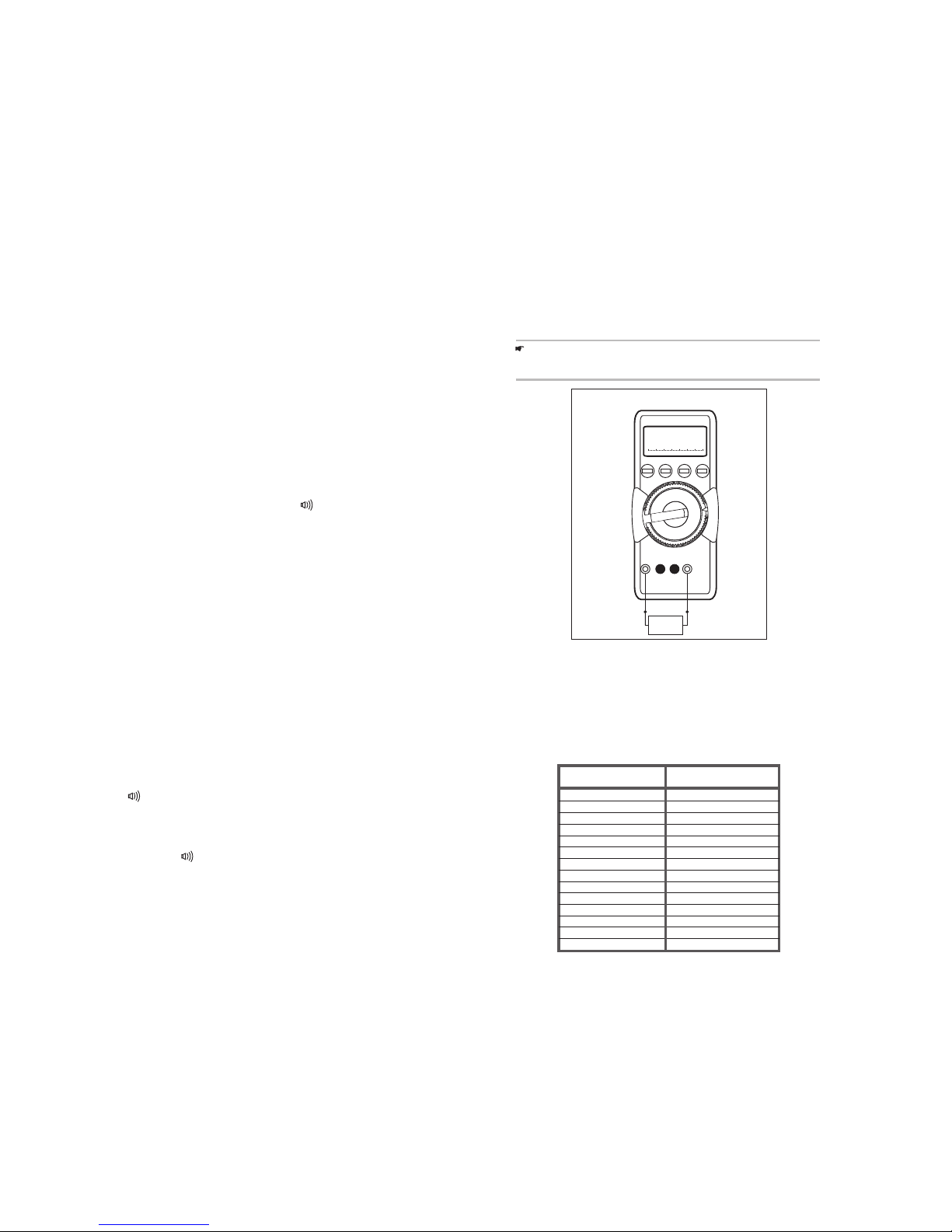
10. Resistance measurement
EVerify that the device under test is electrically dead. External voltages
would falsify the measured result!
ESet the function selector switch (6) to “Ω”.
EConnect the device under test as shown.
lA blown fuse is signalled on the LCD the instant a measured quantity
having a voltage of more than 4 V is applied to the corresponding
connection sockets. Then, the digital display (9) shows the word " FUSE"
lAfter a fuse has blown, eliminate the cause of the overload before using
the meter again !
lReplacement of the fuses is described in section ’’ 18. Maintenance’’.
9.1 AC current measurement with (clip-on) current
transformer( )
ECurrent to voltage clamp with ratio 10 mA : 1mV is used to
measure the current upto 300 A AC with this function
ESet rotary knob at position V(DC+ Yellow)k
“measurement with clip-on
transformer” mode.
EConnect Clamp Output probes to “ ^ ” and “ ” input terminal of this
meter.
EIt has two ranges i.e. 30.00 A and 300.0A. Measurement is possible
with both auto ranging and manual ranging.
AC). Press multifunction ( ey
until a sound beep is heard. This will enter
20
5) Continuously
6) 12 A 5 min, 16 A 30 s
Intrinsic error of digital display
+ (...% of rdg. + ... digits) at reference conditions
Overload
capacity 3)
Overload
Value
Overload
duration
4)
0.5 + 3
0.5 + 3
0.25 + 1
0.25 + 1
0.25 + 1
0.35 + 1
1.0 + 3
(> 10 Digit)
1.0 + 3
(> 10 Digit)
0.5 + 2
0.5 + 5
0.36 A 5)
0.5 +
4)
3
0.5 + 3
0.4 + 1
0.4 + 1
0.4 + 1
0.6 + 1
2.0 + 1
0.25 + 1
1.5 + 4 (> 10 D)
1.5 + 4 ( > 10 D)
Contin-
uously
1000 V
DC
AC
eff/rms
sine
wave
12A 10min
1000 V
DC
Max 10 S
AC
eff/rms
sine
wave
0.5 + 5 (> 10 Digit)
0.5 + 5 (>10 Digit)
0.5 + 5
0.5 + 5
5)
12
DiodeTest
Forward direction Reverse direction
0600
-
+
-
+
Continuity Test
0000
-
+
-
+
Resistance measurement
5
2.i0
-
+
19
1) TRMS measurement
3) 0
At 0 ...+40 C
0
4) With zero adjustment, without zero adjustment + 35 digits
17. Specifications
Reso-
lution Input impedance
V
V ~
3.000 V
30.00 V
300.0 V
1000 V
300.0 mA
3.000 mA
30.00 mA
300.0 mA
30.00 A2)
300.0 A
3.000 mA
300.0 mA
30.00
W
300.0
W
3.000
kW
30.00
kW
300.0
kW
3.000
MW
30.00
MW
2.000 V
1)
1)
1)
1)
1)
1)
1 mV
10 mV
100 mV
1 V
100 nA
1 mA
10 Am
100 Am
10 mA
100 mA
1 Am
100 Am
10 m
W
100 m
W
1
W
10
W
100
W
1 k
W
10 k
W
1 mV
11 M
W // <
40 pF
10 M
W // <
40 pF
10 M
W // <
40 pF
10 M
W // <
40 pF
11 M
W // <
40 pF
10 M
W // <
40 pF
10 M
W // <
40 pF
10 M
W // <
40 pF
Voltage drop approx.
15 mV
150 mV
650 mV
1V
-
-
150 mV
No load voltage
max. 3.2 V
max. 3.2 V
max. 1.25 V
max. 1.25 V
max. 1.25 V
max. 1.25 V
max. 1.25 V
max. 3.2 V
Meas-
urement
Function
Measuring Range
W
A
A ~
V
A
> 10 G
W // <
40 pF
30.00 mV 10 Vm
> 10 G
W // <
40 pF
300.0 mV 100 Vm
11 M
W // <
40 pF
3.000 V 1 mV
10 M
W // <
40 pF
30.00 V 10 mV
10 M
W // <
40 pF
300.0 V 100 mV
10 M
W // <
40 pF
1000 V 1 V
3.000 V
1)
1mV
30.00 V
1)
10mV
300.0 V
1)
100 mV
1000 V
1)
1V
1V
2)
13
lConnect the test leads to the multimeter and join the free ends.
lBriefly press the yellow multi-function pushbutton (5). The meter
acknowledges zero adjustment by a sound signal, the LCD shows
"00.00"(+1digit) and the decimal point flashes. The resistance
measured at the instant the pushbutton is pressed is used as reference
value (max.200 digits) It is automatically deducted from the values
measured thereafter. Zero adjustment can be cleared.
lBy pressing the yellow multifunction pushbutton (5) for a long time and is
acknowledges by two sound signals.
lBy switching the multimeter OFF.
When selecting the function "Diode test and continuity test’’ with the function
selector switch (6), the buzzer is always switched ON.. Repeated brief
pressing of the multifunction pushbutton (5) alternately switches the buzzer off
and on. When pressing the push button for a long time, the buzzer is always
switched ON this is acknowledged by the buzzer sounding twice.
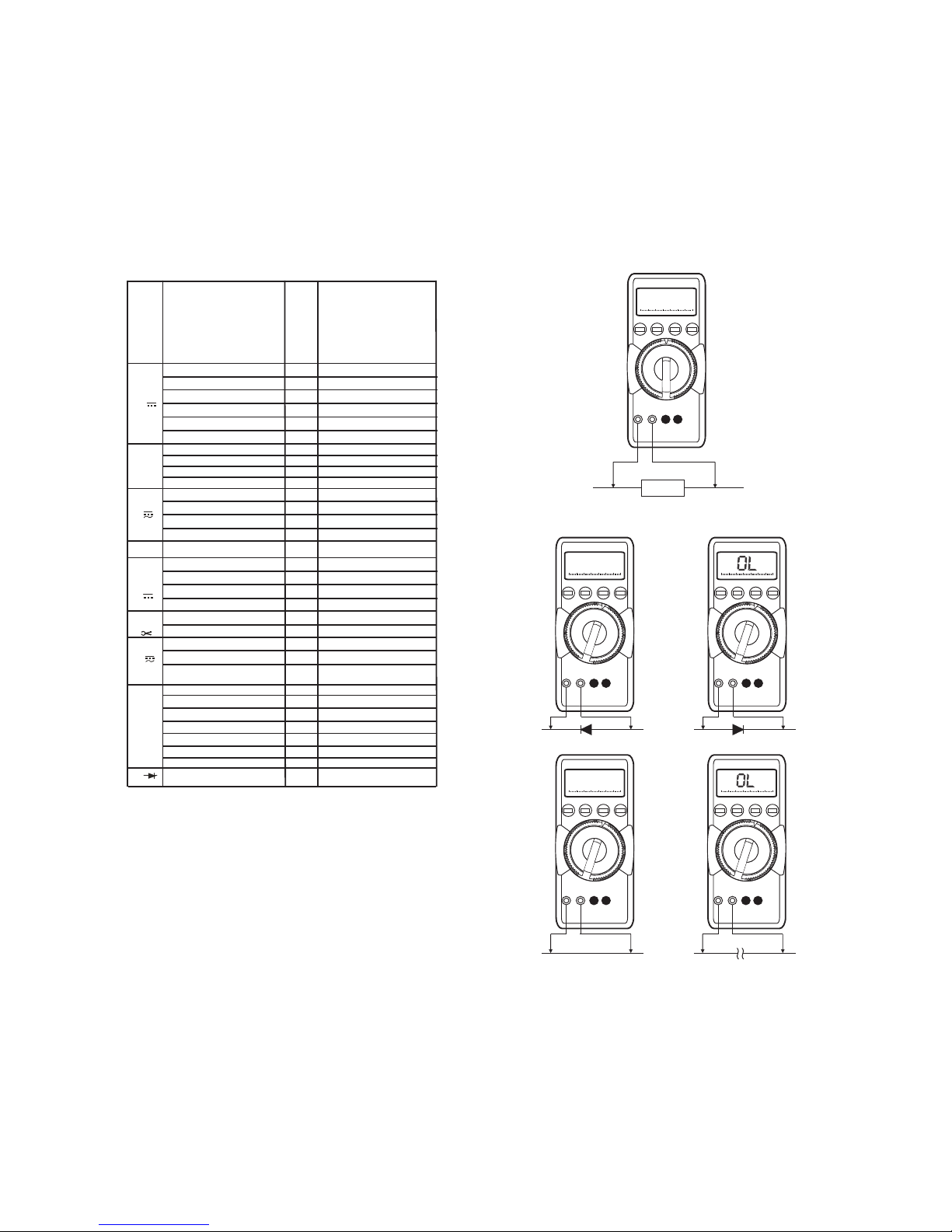
11. Diode test and continuity test
lVerify that the device under test is electrically dead. External voltages
would falsify the measured results!
lSet the function selector switch (6) to "
lconnect the device under test as shown.
Forward direction and/or short circuit:
The multimeter displays the forward voltage in Volts. As long as the voltage
drop does not exceed the maximum display value of 1.999V, you can also test
several series-connected elements or reference diodes with small reference
voltage.
Reverse direction or open circuit:
The multimeter indicates overrange "OL"
"
Zero adjustment on the 30Ω measuring range
When measuring small resistance values on the 30 Ω
eliminate the resistance of the leads and contact resistance by zero
adjustment.
range, you can
Note:
Resistors and semiconductor junction in parallel with the diode falsify the
measured results!
Diode test and continuity test with buzzer
With the "buzzer" function selected, the meter emits a continuous sound
signal on the range 0...approx. 0.7 V.
To switch the Diode Test ON:
Briefly press the yellow multi-function pushbutton (5). The multimeter
acknowledges turn-ON with a sound signal. At the same time,
To switch the
lBriefly press the yellow multi-function pushbutton (5) again.
lThe multimeter acknowledges turn-OFF with a sound signal. The
symbol
the symbol
(18) disappears from the LCD.
Diode Test OFF
(18) appears on the LCD.
18
16.4 After Insulation measurement:
†Voltage displayed after measurement is the voltage present on the device
under test (DUT) due to conductor capacitance.
†Discharge the device under test (DUT) by turning the function selector
switch to “V1M ”.Ω
†Contact with DUT must be maintained. Reduction of voltage can be
observed directly on LCD.
CAUTION !!!
Do not disconnect DUT until voltage has dropped below 25V.
16.5 Evaluation of Measurement Values:
In order to assure that insulation resistance does not violate lower limit values,
the instrument’s intrinsic and influence errors must be taken into
consideration.
The minimum values of insulation resistance can be determined by the
following table, which must be displayed under consideration of maximum
operating error for this meter (under nominal conditions of use) in order to
assure that the required limit values are not violated.
Limit value in MΩMin.Display in MΩ
0.1
0.2
0.5
1
2
5
10
20
50
100
200
500
1000
2000
0.11
0.22
0.55
1.1
2.2
5.5
11
22
55
110
220
550
1100
2200
10.00
Insulation resistance measurement
RINSU

14
12.Capacitance measurement
lVerify that the device under test is electrically dead. External voltages
would falsify the measured results!
lSet the function selector switch (6) to "F”
lConnect the (discharged !) device under test to the " ^ sockets
via test lead.
" and “ F ’’
The zero adjustment can be cleared
lBy pressing the yellow multi-function pushbutton (5) for a long time,
clearance is acknowledged by the two sound signal.
lBy switching the multimeter off.
lConnect the test leads to the meter without device under test.
lBriefly press the yellow multi-function pushbutton (5).
The meter acknowledges zero adjustment by a sound signal, by
displaying "00.00" (+1digit) on the LCD and by a flashing decimal point.
The capacitance measured at the instant the pushbutton is pressed is
used as reference value (max.200 digits). It is automatically deducted
from the values measured thereafter.
Note:
^ " socket. Connect polarised capacitors with the " __ " pole to the "
Resistors and semiconductor junctions in parallel with the capacitor falsify the
measured results!
Zero adjustment on the 30 nF measuring range
When measuring small capacitance values on the 30 nF range, the internal
resistance of the multimeter and the capacitance of the leads can be
eliminated by zero adjustment.
17
16. Insulation resistance measurement
16.1 Before measurement.
ECAUTION !!!
Insulation resistance of only ‘voltage free objects’ can be measured.
Do not touch measuring probes.
†Select the V1MΩ
Ω
Ω
Ω
function using rotary switch
†Connect the measuring probes to “^
This function provides way to measure interference voltage. It also
provides discharge path of 1M to charge present on measuring
objects.
†
†
” and V1M ” input terminals.
Turn the rotary switch to “M is
voltage free.
INSU” when device under measurement
This position by default reads interference voltage. If this voltage is
>50V, insulation resistance measurement is disabled.
16.2 Selecting Test Voltage: 50V or 100V or 250V or 500V or
1000V.
†If VINSU key is briefly activated, currently selected test voltage is
displayed.
†Default values is 500 V. To select other value press and hold VINSU key
until other voltage is displayed. This is confirmed with a sound beep
signal.
16.3 Insulation resistance measurement:
†Press and hold multifunction (yellow) key until display has stabilized.
Insulation measurement is stopped when multifunction key is released.
†An insulation resistance of less than 1M with a test voltage of 500 V, or
less than 2M with a test voltage of 1000 V is indicated with an acoustic
signal.
†Automatic measuring range selection is active for insulation resistance
measurement. There is no provision for the manual selection of
measuring range.
Ω
Ω
Continuous Measurement
†Activation: Press and hold multifunction (yellow) key and simultaneously
press AUTO/MAN key until a sound beep is heard.
ENOTE !!!
The instrument batteries are rapidly depleted during insulation resistance
measurement. Only press and hold the multifunction key as long as is
necessary to take the reading. Continuous measurement as described
below should only be performed if absolutely necessary. Use only Alkaline
manganese batteries in accordance with IEC6 LR03.
High Voltage
Do not touch the conductive ends of the test probes after insulation
measurement has been activated at the instrument. A current with a
value of 2.5 mA (limited by instrument ) may flow over your body, and
although this is not life threatening, the electric shock is distinctly
perceptible. If you are taking measurement at capacitive DUT, for
example a cable, it may be charged with as much as 1000 V,
depending upon the selected nominal voltage. Touching the DUT may
be life threatening.
~

15
Changing over between voltage, frequency and duty cycle
measurement
Repeated brief pressing of the yellow multi-function switch (5) changes the
measuring functions in the following order:
Voltage g
From frequency or duty cycle measurement, directly switching back to voltage
measurement is possible.
lby pressing the yellow multi-function pushbutton (5) for a long time. The
meter acknowledges this by two sound signals. The voltage measuring
range last selected is maintained.
lby operating the function selector switch (6).
frequency g duty cycle g voltage ....
14. Duty cycle measurement
With duty cycle measurement, we can determine the ratio of pulse duration to
cycle time of recurring square-wave signals.
selector switch (6) to V
lConnections are made in the same way as for voltage measurement
(See foot n
lBriefly press the yellow multi-function pushbutton (5) twice.
The meter switches to duty cycle measurement. The duty cycle-that
is the percentage pulse duration of a signal-is displayed on the LCD in%
lSet the function - - - or V~ .
ote 8) on page 23.
13. Frequency measurement
Frequency measurement is possible on all voltage measuring ranges in AC
and DC modes.
lSet the function selector s
lConnections are made the same way as for voltage measurement, See
foot note (8) on page 21.
lBriefly press the yellow multi-function pushbutton (5)
lThe multimeter switches to frequency measurement. The frequency is
displayed on the LCD.
lSee section "17. Specifications" for the lowest measurable frequencies
and the maximum permissible voltages.
witch (6) to V ~ or, V - - - .
Notes :
The applied frequency must remain constant during the duty cycle
measurement. Change -over between voltage, frequency and duty cycle
factor measurement is done as described in the preceding section.
lThat is:
Pulse duration
Duty cycle (%) = ———————— x 100
Cycle duration
16
We can exit the temperature measurement function
lby pressing the yellow multi-function switch (5) longer, this is confirmed
by the two sound signals.
lby changing the function selector switch.
15. Temperature measurement
The meter Pt100 and Pt1000
temperature sensors in the range from -
ESet the function selector switch (6) to “
EConnect the sensor to the two unblocked terminals.
EBriefly press the yellow multifunction pushbutton (5). The multimeter
switches to temperature measurement, it automatically detects the
connected sensor (Pt100 to Pt1000) and shows the measured temper
allows you to measure temperature with
0 0
200 (- 100) C...+850 C
Ω”
ature
0
in C on the digital display.
Sensor lead resistance up to 50 Ω
Lead resistance of sensors upto 50 ohms can be compensated as follows:
EBriefly press the yellow multi-function pushbutton (5) again.
The LCD now displays the resistance value which the multimeter
automatically considers after selecting the temperature measuring
range. We can recognise that this is the resistance correction value on
the temperature measuring range. The “
simultaneously shown on the display.
EYou can set the lead resistance correction value as follows:
EPress the DATA- MIN/MAX pushbutton (3) to increment the value, or the
AUTO/MAN pushbutton (4) to decrement the value. Each time the
pushbutton is briefly pressed, the value changes by one digit.
EBriefly press the yellow multi-function pushbutton (5) again.
The LCD displays the measured temperature. The flashing decimal
point shows you that we have entered a correction value for the lead
resistance. The correction value is retained as long as multimeter is
switched on.
EEach time the yellow multi-function pushbutton (5) is briefly pressed,
the display changes between measured temperature and correction
value of the lead resistance.
0C’’ character is
Notes:
It is not possible to switch over to temperature measurement when the 30Ω
resistance range is selected.
Notes:
For the lead resistance, the actual value measured on the digital
multimeter should be taken as correction value and not any specified value.
Table of contents
Other Sifam Tinsley Multimeter manuals


