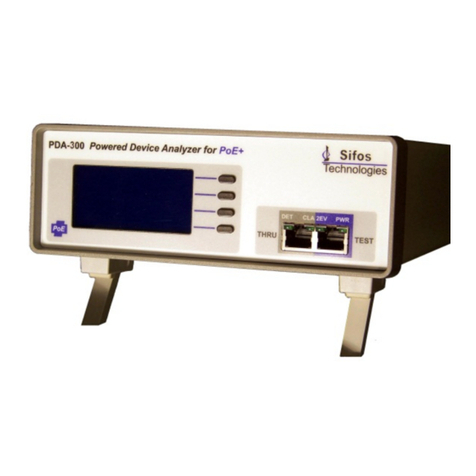
Sifos Technologies PowerSync PDA-300 Product manual

PDA-300 Reference Manual
January 21, 2014 Sifos Technologies Page
1
Sifos Technologies
PowerSync Device Analyzer
PDA-300
Technical Reference
Manual
Version 3.6
Revised January 21, 2014
Copyright © 2014 Sifos Technologies
®

PDA-300 Reference Manual
January 21, 2014 Sifos Technologies Page
2
Sifos Technologies, Inc.
(978) 640-4900 Phone
(978) 640-4990 FAX
Disclaimer
The information contained in this manual is the property of Sifos Technologies, Inc., and is furnished for use by recipient
only for the purpose stated in the Software License Agreement accompanying the user documentation. Except as
permitted by such License Agreement, no part of this publication may be reproduced, stored in a retrieval system, or
transmitted, in any form or by any means, without the prior written permission of Sifos Technologies, Inc.
Information contained in the user documentation is subject to change without notice and does not represent a
commitment on the part of Sifos Technologies, Inc. Sifos Technologies, Inc. assumes no responsibility or liability for any
errors or inaccuracies that may appear in the user documentation.
Warranty
Sifos Technologies Inc., warrants to recipient that hardware (“Hardware”) and the tangible media on which it supplies
Software will be free from significant defects in materials and workmanship for a period of 12 months from the date of
delivery (the “Warranty Period”), under normal and intended use and conditions. Sifos also warrants that during the
Warranty Period, the Software that it supplies will operate substantially in accordance with the specifications supplied by
Sifos for such Software. Sifos does not warrant that the functions contained in the Software will meet a specific
requirement or that the operation will be uninterrupted or error free. Sifos shall have no warranty obligations whatsoever
with respect to any Software which has been modified in any manner by any third party.
Defective Product under warranty shall be, at Sifos’ discretion, repaired or replaced or a credit issued for an amount equal
to the price paid for such Product provided that: (a) such Product is returned to Sifos Technologies after first obtaining a
return authorization number and shipping instructions, freight prepaid, to Sifos’ location in the United States; (b) Recipient
provides an explanation of the defect or Software failure claimed; and (c) the claimed defect actually exists and was not
caused by fault, neglect, accident, misuse, improper storage, improper installation, improper repair (other than by Sifos or
its agents), fire, flood, lightning, power surges, earthquake or alteration (unless such alteration performed by Sifos or its
agents). Sifos will ship repaired Products to recipient, freight prepaid, within ten (10) working days after receipt of
defective Product. Except as otherwise stated, any claim on account of defective materials or for any other cause
whatsoever will conclusively be deemed waived by recipient unless written notice thereof is given to Sifos Technologies,
Inc. within the Warranty Period. Product will be subject to Sifos Technologies’ standard tolerances for variations.
TO THE EXTENT PERMITTED BY APPLICABLE LAW, ALL IMPLIED WARRANTIES, INCLUDING BUT NOT LIMITED
TO IMPLIED WARRANTIES OF MERCHANTABILITY, NONINFRINGEMENT AND FITNESS FOR A PARTICULAR
PURPOSE, ARE HEREBY EXCLUDED, AND THE LIABILITY OF SIFOS, IF ANY FOR DAMAGES RELATING TO ANY
ALLEGEDLY DEFECTIVE PRODUCT SHALL BE LIMITED TO THE ACTUAL PRICE PAID BY THE PURCHASER FOR
SUCH PRODUCT. IN NO EVENT WILL SIFOS TECHNOLOGIES BE LIABLE FOR COSTS OF PROCUREMENT OF
SUBSTITUTE PRODUCTS OR SERVICES, LOST PROFITS, OR ANY SPECIAL DIRECT, INDIRECT,
CONSEQUENTIAL OR INCIDENTAL DAMAGES, HOWEVER CAUSED AND ON ANY THEORY OF LIABILITY,
ARISING IN ANY WAY OUT OF THE SALE AND/OR LICENSE OF PRODUCTS OR SERVICES TO RECIPIENT EVEN
IF ADVISED OF THE POSSIBILITY OF SUCH DAMAGES AND NOTWITHSTANDING ANY FAILURE OF ESSENTIAL
PURPOSE OF ANY LIMITED REMEDY.

PDA-300 Reference Manual
January 21, 2014 Sifos Technologies Page
3
Table of Contents
1. IEEE 802.3at Powered Devices ........................................................................................ 5
1.1. PoE Overview .......................................................................................................................5
1.2. PD Detection ........................................................................................................................5
1.3. PD Classification ...................................................................................................................6
1.4. Power Application & Overload Conditions.............................................................................7
1.5. Link Layer Discovery Protocol................................................................................................8
1.6. Disconnects and Power Removal...........................................................................................8
2. PDA-300 Measurement and Test Capabilities ................................................................. 9
2.1. PDA-300 Interfaces ...............................................................................................................9
2.2. PDA-300 Functional Overview...............................................................................................9
2.3. Automated 802.3at PoE Test Suite ......................................................................................10
2.4. PD Load Monitor ................................................................................................................11
2.5. User Defined Tests..............................................................................................................11
2.6. PDA-300 Technical Specifications ........................................................................................13
2.6.1. Input/Output .........................................................................................................................................13
2.6.2. Source Specifications.............................................................................................................................13
2.6.3. Measurement Specifications .................................................................................................................13
2.6.4. Physical and Environment .....................................................................................................................15
2.6.5. Certifications .........................................................................................................................................15
2.6.6. Safety Precautions.................................................................................................................................15
3. PDA-300 Screen Menus ................................................................................................ 17
3.1. PDA-300 Main Menu ..........................................................................................................17
3.2. 802.3at PoE Test Menu .......................................................................................................17
3.3. PD Load Meter Menu..........................................................................................................18
3.4. User-Defined Test Menu .....................................................................................................18
3.4.1. User-Defined Test Configuration...........................................................................................................19
3.4.2. Test Example: Type-2, PD Class 4 Test ..................................................................................................19
4. PDA Interactive............................................................................................................ 21
4.1. Overview............................................................................................................................21
4.2. Setup and Configuration .....................................................................................................21
4.2.1. Configuring PDA Interactive to a Specific RS-232 Serial Port ................................................................21
4.2.2. PDA Interactive Software Files ..............................................................................................................21
4.3. PDA Interactive Main Menu ................................................................................................21
4.4. Automated PD Testing from PDA Interactive .......................................................................22
4.4.1. Each Cycle Report Mode .......................................................................................................................22
4.4.2. Accumulate Report Mode .....................................................................................................................22
4.4.3. PD Under Test Description ....................................................................................................................24
4.4.4. PDA Interactive Results Display.............................................................................................................24

PDA-300 Reference Manual
January 21, 2014 Sifos Technologies Page
4
4.5. PDA Interactive Load Meter ................................................................................................24
4.5.1. General Operation.................................................................................................................................24
4.5.2. Ppeak_max and Pclass_max Limit Checking & Violation Capture.........................................................25
4.5.3. Watt∙hour meter ...................................................................................................................................26
4.5.4. Load Monitor Reporting ........................................................................................................................26
4.5.5. Load Meter Display Is Not Real Time ....................................................................................................27
4.6. Store Trace to Disk..............................................................................................................27
4.6.1. Keeping Power On When a Trace Stops ................................................................................................28
4.6.2. Measured Power Snapshot is Not Real Time ........................................................................................28
4.7. User-Defined Tests .............................................................................................................28
5. PDA-300 Firmware Upgrades ....................................................................................... 29
6. PDA-300 Remote Control Interface ............................................................................... 31

PDA-300 Reference Manual
January 21, 2014 Sifos Technologies Page
5
1. IEEE 802.3at Powered Devices
1.1. PoE Overview
Power-over-Ethernet (PoE) involves the distribution of DC power from various Power Sourcing Equipment (PSE’s) to
Powered Devices (PD’s). Standardized PoE is governed by the IEEE 802.3 standard, primarily Clause 33. The
original IEEE standard for PoE was referred to as IEEE 802.3af (2003) and has since been replaced by IEEE 802.3at
(2009).
PSE’s exist in several form factors including end-span Ethernet switches and routers and mid-span single or multi-port
power injectors. PSE’s are able to layer DC power onto an Ethernet LAN connection by injecting DC power into the
primary center taps of two differential pair transformers such that the DC voltage appears as a common mode voltage
to the differential Ethernet LAN signals and therefore (ideally) has no detrimental impact to the transmission of those
signals from a transmitter to a receiver. Similarly, PD’s can extract the DC power from the primary center taps on
their Ethernet transformers and utilize that power in place of an alternative power supply.
Unlike AC Power from an outlet, PoE Power is a form of “smart power” where power is only applied after a PSE
recognizes that a PD has been connected and the PSE may, for various reasons, refuse power, remove power, or in
certain cases, actually negotiate with the PD to allow a particular power load.
The IEEE 802.3at standard imposes many rules on both PSE’s and PD’s to assure they will interoperate properly over a
wide range of circumstances including distances of up to 100 meters between PSE and PD. Within these rules
however, PSE’s are given a wide range of implementation discretion and in fact, there are many variations today in
how PSE’s actually carry out their various responsibilities with regard to PD power delivery.
With the advent of 802.3at, PSE’s and PD’s are segregated into two types: Type-1 and Type-2. Type-1 PSE’s and
PD’s are restricted to power levels ranging from ~0.4 to 13 watts (or 15.4 watts at the PSE interface). Type 2 PD’s
may draw up to a maximum of 25.5 watts (or 30 watts at the PSE interface). However, Type-2 PD’s may not draw
more than 13 watts until a (Type-2) PSE grants them permission to do so. Type-2 PSE’s may utilize either physical
signaling or a Link Layer Discovery Protocol message to grant this permission. Type-2 PSE’s and PD’s must be fully
backward compatible with older 802.3af (and Type-1) equipment –that is a Type-1 PSE must tolerate the connection
of a Type-2 PD and a Type-2 PD must accept the power limitations of a Type-1 PSE. Finally, Type-1 PSE’s can
source from 44 to 57 VDC while Type-2 PSE’s must source between 50 and 58 VDC when powered.
The PDA-300 is designed to test many of the critical attributes of a Powered Device such that the Power Device will
have a very high likelihood of successfully interoperating with the wide variety of PSE’s and network connection
circumstances.
1.2. PD Detection
A PSE only furnishes power to a PD after determining that a PD
has been connected. PD’s must be constructed to accept power
from either of two different TIA Category 5 cable pair groups:
ALT-A consisting of TIA pair 2(orange) and 3(green), the
10/100BaseT transmit and receive pairs, or ALT-B consisting of
pair 1(blue) and 4(brown). Additionally, PD’s must be
constructed to accept either positive or negative voltage polarity
from the incoming powered pairs (see Figure 1.1). All together, this represents 4 different power input scenarios or
“quadrants” that a compliant PD must process.
The IEEE standard requires that a PD present a resistive
“signature” (R_detect) in the voltage band of 2.7 Volts to 10.1
Volts. This 25kk resistance must appear on the same
pairs that will be powered by the PSE and must be seen common
mode, that is, it should be connected between center taps of
Ethernet transformer primary coils. This is depicted in Figure 1.2.
The PSE is then responsible for discerning the presence of this
resistance value in order to qualify that the connected device is
indeed a Powered Device. Since the PSE cannot assume anything
about the resistance characteristic below 2.7 volts, it must perform
an AC Resistance measurement to resolve the PD “detection
signature”. PSE’s utilize a wide variety of methods to perform
Pair
2
3
1
4
ALT A
ALT A
ALT B
ALT B
MDI
+
--
+
MDI-X
MDI
+
--
+
MDI-X
Pair
2
3
1
4
ALT A
ALT A
ALT B
ALT B
MDI
+
--
+
MDI-X
MDI
+
--
+
MDI-X
Figure 1.1 PoE Powering Permutations
Figure 1.2 PD Detection Signature
R_detect
25K
Powered Pair 1
Powered Pair 2
DC VOLTS
2.7VDC
10.1VDC
C_detect
.085F
Diode Bridge
R_detect
25K
Powered Pair 1
Powered Pair 2
DC VOLTS
2.7VDC
10.1VDC
C_detect
.085F
R_detect
25K
Powered Pair 1
Powered Pair 2
DC VOLTS
2.7VDC
10.1VDC
C_detect
.085F
Diode Bridge

PDA-300 Reference Manual
January 21, 2014 Sifos Technologies Page
6
this measurement in the voltage band between 2.7 and 10.1 volts.
One design detail that can impact the delivery of PoE is the EMI
termination often used by Ethernet ports to suppress high frequency noise
and common mode surges. Traditionally, EMI terminations involved
coupling transformer primary center taps to ground through a small
resistance. With PoE, the center taps of those transformers must be DC
isolated from ground. PSE’s and PD’s must therefore implement EMI
terminations with capacitive coupling in order to isolate ground from PoE
power and to DC isolate the termination resistances in those center tap
connections. (see Figure 1.3)
The selection of values for EMI termination resistance and capacitance can have some bearing on the detection
signature resistance and shunt capacitance measured by the PSE during detection. PSE’s are given the discretion to
invalidate a detection signature if is found to be greater than 0.15F(C_detect) (see Figure 1.2). To complicate
things further, the exact method used by the PSE to measure both R_detect and C_detect can affect the “perceived”
impact of the EMI termination circuits in contributing to those measurements. PD’s are required to present a minimum
C_detect of 0.05Fin order to help prevent confusion with EMI termination circuits.
1.3. PD Classification
The IEEE PoE standard provides a means by which PD’s can
communicate to a PSE the level of power draw the PD will add
when powered by the PSE. This process is referred to as PD
Classification. A PD is required to draw a fixed DC current
(I_class) when the incoming voltage from the PSE ranges
between 14.5VDC and 20.5VDC (see Figure 1.4). The amount
of DC current flowing to the PD then signals back to the PSE
the desired PD power draw. This scheme is not very granular
and it allows for PD’s that draw zero current in the
classification voltage band to be fully ambiguous (Class 0)
about their power requirements.
The Classification signaling scheme works according to the
following table:
PD Class Signature
PD Class
Expected PD Power Load
0 to 4 mA
0
0.50 to 13.00 Watts
9 to 12 mA
1
0.50 to 3.84 Watts
17 to 20 mA
2
3.84 to 6.49 Watts
26 to 30 mA
3
6.49 to 13.00 Watts
36 to 44 mA
4
13.00 to 25.50 Watts
Classification is an optional process for Type-1 PSE’s and a mandatory process for Type-2 PSE’s. Classification
measurements are completed typically in less than 75 msec.
Under the newer IEEE 802.3at standard, classification functionality
is extended so that a classification measurement could potentially
signal to a Type-2 PD that the PSE is capable of providing Type-2
power levels (up to 25.5 watts at the PD). This is achieved by
having the Type-2 PSE repeat the classification measurement a
second time, a process referred to as Two-Event Classification (see
Figure 1.5). In order for this scheme to work, all Type-2 PD’s are
required to internally discharge the classification voltage (14.5V to
20.5V) immediately following each classification measurement (or
“event”) so that the two distinct classification pulses can be
recognized. (The PSE voltage will drop to between 7 and 10 volts
during this time interval, thus providing some power for the PD to
“remember” the 2-event grant.)
The Type-2 PD must apply a Mark Event load current in the range of 0.25 to 4 mA to facilitate this discharging after
each class event. This in turn allows the Type-2 PD to discriminate the two-event classification so that it can draw
power beyond 13 watts following power-up. In short, the two-event classification serves as a full Type-2 power
“grant” from the PSE to the PD.
75
1000pF
EMI Termination
75
1000pF
EMI Termination
Figure 1.3 EMI Terminations
0mA-
45mA
Powered Pair 1
Powered Pair 2
DC VOLTS
14.5VDC
20.5 VDC
0mA-
45mA
Powered Pair 1
Powered Pair 2
DC VOLTS
14.5VDC
20.5 VDC
Figure 1.4 PD Classification Signature
PSE Detection
Measurement Two-Event
Classification
14.5VDC
20.5VDC Class
Event Class
Event
Mark
Event Mark
Event
Power
Up
PSE Detection
Measurement Two-Event
Classification
14.5VDC
20.5VDC Class
Event Class
Event
Mark
Event Mark
Event
Power
Up
Figure 1.5 Two-Event Classification

PDA-300 Reference Manual
January 21, 2014 Sifos Technologies Page
7
Type-2 PSE’s have the option to utilize Link Layer Discovery Protocol (LLDP) as an alternative to providing two-
event classification for the purpose of granting power levels beyond 13 watts to the Type-2 PD. Many Type-2 end-
span PSE’s will in fact choose to use LLDP instead of two-event classification because LLDP offers much better power
management granularity. LLDP is described below in section 1.5.
Type-2 PSE’s also have the freedom to utilize two-event classification with all PD’s, not just Type-2 PD’s. This is
because older 802.3af (Type-1) PD’s should be insensitive to the occurrence of a repeat class measurement preceding a
power-up.
1.4. Power Application & Overload Conditions
PSE’s will apply DC power to a PD only if PD Detection completes successfully and if the PSE has sufficient power
available as determined through PD Classification and/or knowledge of available power resources. Power is provided
with a DC voltage ranging from 44V to 57V at the PSE end of the connection. Because of resistive cable loss,
voltages present at the PD input can range from 37V to 57V. The PD must receive this DC power from either the
ALT-A or ALT-B pairs (see section 1.2) and accept
either positive or negative polarity.
During initial power-up, a PD may draw a surge current
to charge power supply capacitances. Surge loads must
be tolerated by the PSE for up to at least 50 msec
(Tinrush) so long as they do not exceed 400mA
(Iinrush_pd). PD’s are responsible for regulating
surge current to 400mA or less if they present very large
load capacitances. Capacitive charging “energy” can be
expressed as the product of power and time so a 48V
PSE supplying 400mA for 50msec furnishes 0.96 watt-
sec of charging energy to the PD.
Following the Inrush interval, PD’s are required to restrict average (or continuous) power draw to a level below
Pclass_pd(max), or the maximum power allowed to the specified PD Class. The PD may briefly exceed this power
level with load transients up to the value of Ppeak_pd(max), so long as those load transients do not exceed a duration
of Tcut_min, or 50msec. These requirements are depicted graphically in Figure 1.6. Values for Pclass_pd(max) and
Ppeak_pd(max) are shown in the table below.
A peak power violation occurs
when a PD instantaneously draws
more power than specified by
Ppeak_pd(max) for that PD
Class. A class power violation
occurs when a PD exceeds
Pclass_pd(max) for more than 50
msec (contiguous) or for greater
than 5% of time on average (see
Figure 1.6). Any violation may
lead to power removal by a PSE.
PSE’s are allowed very wide
discretion in monitoring and
reacting to class and peak power violations. Many Type-1 PSE’s will treat all Type-1 PD’s as Class 0 meaning Class 1
or 2 power violations are completely ignored. Many other PSE’s use more conservative thresholds than
Pclass_pd(max) and Ppeak_pd(max) meaning they will tolerate PD’s that over-draw power relative to their specified
classification. LLDP capable PSE’s may use granted power values for Pclass_pd(max).For these reasons, PSE’s
generally are not useful as test vehicles for assessing PD power compliance.
IEEE 802.3at places a special requirement on Type-2 PD’s that restricts initial
start-up power draw to Type-1 levels (13 watts or less) until either the PSE is
assured that the initial Inrush period is completed or until an LLDP
negotiation is completed. If the PSE provides two-event classification as a
means to grant Type-2 power to a Type-2 PD, then the PD must wait for at
least 80 msec (Tdelay) before stepping up to a power draw in excess of 13
watts (see Figure 1.7). If a Type-2 PSE does not provide two-event
classification, then the PD may need to wait up to tens seconds to start a link
layer LLDP negotiation with the PSE and subsequently may need to wait
indefinitely for a power grant from the PSE authorizing power draw in excess
PD Class
LLDP Usage
Pclass_pd(max)
Ppeak_pd(max)
0
Non-LLDP
13.00 W
14.40 W
LLDP
PD Requested Power
1
Non-LLDP
3.84 W
5.00 W
LLDP
PD Requested Power
2
Non-LLDP
6.49 W
8.36 W
LLDP
PD Requested Power
3
Non-LLDP
13.00 W
14.40 W
LLDP
PD Requested Power
4
2-Event Grant
25.50 W
28.31 W
LLDP Grant
PD Requested Power
1.11 X PD Req.Pwr
Type-1 Pclass
Type-2 Pclass
Two-Event
Class
> 80msec
Inrush
Power-
Up 2-Event Grant
Response
Type-1 Pclass
Type-2 Pclass
Two-Event
Class
> 80msec
Inrush
Power-
Up 2-Event Grant
Response
Figure 1.7 Type-2 PD Start-Up
Figure 1.6 Powered PD Loading Requirements
Tcut_min
(50msec)
400mA
Inrush
Interval
(50msec)
Valid
Transient
Power-
Up
Ppeak_pd(max)
Pclass_pd(max)
Tcut_min
(50msec)
Ppeak
Violation
Pclass
Violation
Tcut_min
(50msec)
400mA
Inrush
Interval
(50msec)
Valid
Transient
Power-
Up
Ppeak_pd(max)
Pclass_pd(max)
Tcut_min
(50msec)
Ppeak
Violation
Pclass
Violation

PDA-300 Reference Manual
January 21, 2014 Sifos Technologies Page
8
of 13 watts. So generally, Type-2 PD’s must have an “idle” state where they draw less than 13 watts until allowed by
the PSE to exceed that threshold.
1.5. Link Layer Discovery Protocol
Type-2 PD’s are required to support a new Link Layer Discovery Protocol (LLDP) whereby a powered PD must
negotiate with a PSE for a specific power level if that power level exceeds 13 watts at the PD. LLDP is an industry
standard (IEEE 802.1) protocol historically used to allow network management software to “discover” the topology of
a LAN including all end-terminal devices. As a MAC layer protocol, LLDP exists only on a single link, for example,
between an Ethernet switch port and a PC LAN interface. Information gleaned from LLDP is then typically stored in
SNMP MIB objects for access by management software.
Under the 802.3at standard, LLDP was extended to define new PoE LLDP protocol message fields and associated
SNMP MIB’s. These fields are used both for mutual identification of PSE and PD traits as well as for a non-
synchronized protocol to negotiate a power level by the PD. This represents an unorthodox use of LLDP since LLDP
for PoE is a “stateless” protocol that requires Requests and Grants in order for the PSE and PD to agree on a power
level.
A big advantage of LLDP is that it allows power load specification to 0.1 watt. This in turn allows PSE’s to budget
shared power resources across many switch ports with 0.1 watt granularity per port. A second advantage of LLDP is
that it allows re-negotiation of PD power requirements after a PD is powered. This allows PSE’s and PD’s to make
more refined decisions about power-saving modes and power priorities across many powered devices. LLDP is only
available to end-span PSE’s since mid-span PSE’s do not terminate Ethernet connections. Type-2 mid-span PSE’s
must therefore use two-event classification and grant the full 25.5 watts to each Type-2 PD that connects.
Type-2 (end-span) PSE’s that deploy LLDP to grant high power levels to a PD will generally NOT use two-event
classification since these PSE’s will want to restrain PD power draw to 13 watts or below until the negotiation for
power is completed. Type-1 (end-span) PSE’s and Type-1 PD’s are allowed but not required to incorporate LLDP for
PoE.
The PDA-300 utilizes only two-event classification for all Type-2 power grants. The PDA-300 will enable Ethernet
connections and any Ethernet protocols, including LLDP, to pass via the THRU port to the PD that is connected to the
TEST port. The Sifos PowerSync Analyzer (PSA-3000) can be utilized to emulate LLDP PoE protocol from a PSE
via the PDA-300 THRU port.
1.6. Disconnects and Power Removal
When a PD is disconnected from a PSE, the PSE is required to withdraw power. Power will not be restored until that
PSE port successfully detects a new PD connection.
A PSE detects that a PD has been disconnected in one of two ways: DC MPS method or AC MPS method. The DC
MPS method involves a constant monitor of load current to the PD. If the PSE using DC MPS method determines that
load current has dropped below 10mA for between 300 msec and 400 msec, the PSE will withdraw power immediately.
Naturally, a disconnected PD will draw 0 mA, so shutdown occurs
300 to 400 msec after disconnect.
The AC MPS method involves constant monitor of an impedance
signature similar to a valid detection signature. An AC
measurement is made so that it can be superposed from a high
impedance source on the DC supply voltage. PSE’s are given wide
discretion on how this measurement is performed during the
powered-on state. A powered PD is required to present an
impedance across the powered pairs that combines 26.3kor less
in parallel with at least 0.05F.
In reality, since PD’s can’t know which method any PSE is using, the more constraining case is DC MPS. A PD
drawing 10mA for example will present to an AC MPS PSE as an effective impedance of no higher than 5.7 k(57V
/10mA). This will easily satisfy an AC MPS signature measurement that maintains power for any impedance below
26.3k.
The DC MPS scheme allows for PD’s to drop below 10 mA on a periodic or intermittent basis to save power. A PD
that behaves this way may operate below 10mA for up to 250msec out of every 325msec and remain powered by the
DC MPS method PSE (see Figure 1.8).
Figure 1.8 DC MPS Requirements
10mA >75 msec
DC MPS
Requirements
<250 msec
10mA
10mA >75 msec
DC MPS
Requirements
<250 msec
10mA

PDA-300 Reference Manual
January 21, 2014 Sifos Technologies Page
9
2. PDA-300 Measurement and Test Capabilities
The PDA-300 operates both as a stand-alone instrument and as an analyzer under control of PC hosted software. As a
stand-alone instrument, it may be used for rapid qualification or troubleshooting of a Powered Device (PD) in either a
manufacturing or field setting. As a software managed analyzer, it is highly useful for design verification and QA
functions to assure interoperability under the IEEE 802.3at standard and to build confidence that PD’s are properly
specified for purposes of classification and mutual identification with PSE’s.
2.1. PDA-300 Interfaces
The PDA-300 is designed to connect to a single PD via the Test Port.
Generally, this connection should be through a short Cat5e or Cat6 patch
cable. This is the only connection required to perform stand-alone
instrument testing of the PD.
The Test Port is transformer-coupled to a Thru Port (see Figure 2.1).
The Thru Port allows Ethernet communications to be conducted with a
PD while it is being powered by the PDA-300. The PDA-300 will
support 10BaseT, 100BaseT, and 1000BaseT links between the Thru
Port and the Test Port. This feature is particularly useful for controlling
and monitoring a PD during Load Monitor testing (see section 2.4).
It is also useful in support of LLDP protocol and functional tests on any
LLDP-capable PD.
The PDA-300 also includes a Serial Port (DB-9) to enable remote control of the PDA, primarily under control of PDA
Interactive software. The serial port requires a standard (non null-modem) serial connection to a PC that will host
PDA Interactive. PDA Interactive adds significant capabilities in the areas of test reporting, data collection, and load
monitor features and analysis.
2.2. PDA-300 Functional Overview
The PDA-300 incorporates three basic functions:
1. 802.3at PoE Test Suite
2. Load Monitor (or Load Meter)
3. User-Defined Tests
The 802.3at PoE Test Suite is a fully automated
sequence of Powered Device measurements that are
evaluated against IEEE 802.3at published
specifications. The fundamental purpose of these
specifications is to assure PD interoperability with
any 802.3at compliant PSE regardless of connection
distance. The test may be run from the PDA-300
front panel or from PDA Interactive software and is
useful across a wide spectrum of application
environments including PD design, quality assurance, manufacturing sample analysis, and field verification or
troubleshooting. The 802.3at Test Suite will be discussed in detail in section 2.3.
The Load Monitor function adds to the overall test coverage of the PDA-300 by performing both static and dynamic
PD loading analysis over time and port voltage. Many PD’s require external control or intervention over the LAN in
order to produce maximum power states, minimum power states, and peak transient power conditions. The Load
Monitor operates continuously for arbitrarily long time periods while PD’s are manipulated or exposed to conditions
that will affect power load. The PD Load Monitor will be reviewed in section 2.4.
A third basic function is User-Defined Tests. Custom Tests allow users to create specific test sequences for specific
types of PD’s that have specified characteristics. These test sequences typically are subsets of the 802.3at Test Suite
with combinations of 802.3at standard test criteria and user-specified test criteria. The essential purpose of a User-
Defined Test is to produce a PASS/FAIL indication for a particular PD type given only the tests deemed most
important for that PD. As such, this feature is useful in manufacturing or field troubleshooting type applications. This
topic will be addressed further in section 2.5.
PDA-100
PoE
PDA Per-Pair Connection
TEST
PORT
(to PD)
THRU
PORT
ALT/Polarity Switching
PoE Testing Resources
Controller / I-O
Serial Port
PDA-100
PoE
PDA Per-Pair Connection
TEST
PORT
(to PD)
THRU
PORT
ALT/Polarity Switching
PoE Testing Resources
Controller / I-O
Serial Port
Figure 2.1 PDA-300 Interfaces
Figure 2.2 PDA-300 Applications and Coverage
APPLICATION
Design
Verification Quality
Assurance Manufacture Field Test
802.3at Test Suite
Time & Coverage
Load Monitor
User-Defined
Tests
APPLICATION
Design
Verification Quality
Assurance Manufacture Field Test
802.3at Test Suite
Time & Coverage
Load Monitor
User-Defined
Tests

PDA-300 Reference Manual
January 21, 2014 Sifos Technologies Page
10
2.3. Automated 802.3at PoE Test Suite
Many features of a Powered Device (PD) that are critical for interoperability with all 802.3at compliant PSE’s can be
assessed through a fully automated sequence of measurements by the PDA-300. The PDA-300 will emulate both
Type-1 and Type-2 PSE’s (see section 1.1) and will support PD power loads beyond the maximum allowed 25.5 watts.
Testing is performed in each of four electrical “quadrants” defined earlier in section 1.2.
The 802.3at PoE Test Suite may be executed on a stand-alone PDA-300 or it can be controlled from PDA Interactive
software where it will also produce colorful spreadsheet reports with statistics (see Figure 2.3). In either case, test
criteria applied to each measurement are derived from the IEEE 802.3at specification.
Test parameters are aligned to one of three categories: Unpowered PD, Powered Type-1 PSE, and Powered Type-2
PSE. Unpowered PD testing includes PD characteristics that are relevant to PD Detection, PD Classification, and start-
up. Powered Type-1 testing assesses PD load behaviors following power-up from a “typical” Type-1 PSE. Powered
Type-2 testing assesses PD load behaviors following power-up from a “typical” Type-2 PSE.
Many of the
Unpowered PD
measurements are
always performed in
all four quadrants,
that is ALT-A and
ALT-B pairs with
MDI (positive) and
MDI-X (negative)
polarity. All of the
remaining test
parameters can be
tested in either a
single quadrant,
ALT-A + MDI, or
may optionally be
tested in all four
quadrants.
The table following presents each of the measurement parameters and associated 802.3at acceptance criteria. All
acceptance criteria appear in or are derived from IEEE 802.3at (final draft 4.2) dated August, 2009.
Category
Test Parameter
Description
Acceptance Criteria
Unpowered PD
R_detect
Detection resistance (2.7 to 10.1 V band)
23.7 to 26.3 k
C_detect
Detection capacitance (2.7 to 10.1 V band)
0.05 to 0.12 F
I_class
Classification signature current (15 –20 V)
0-4, 9-12, 17-20, 26-30,
or 36-44 mA
Class
PD Class determined from classification
0, 1, 2, 3, or 4
Type
PD Type determined from classification
1 or 2
V_on
Voltage at which PD draws load current
30 to 42 VDC
V_off
Voltage at which PD stops load current
> 30 VDC
Inrush_E
Capacitive charging energy (watt-sec) over worst
20msec sub-interval of Inrush interval –a failure
indicates an Iinrush_pd violation while a pass
indicates very low inrush interoperability risk
< 0.38 watt-sec
Powered from
Type-1 PSE
Single-Event
Classification
and
48V DC Source
Pclass_pd_1
Average PD power draw following the 50msec
inrush interval
(See section 1.4,
Class 4 restricted to
Class 0 power levels)
Ppeak_pd_1
Maximum PD transient load following the
50msec inrush interval*
Max_Load_1
Maximum transient load current sampled
following the 50msec inrush interval*
10 to 300 mA
MPS_Load_1
Minimum load current sampled after power-up.
(Note: PD’s meeting DC MPS signature criteria
described in section 1.6 will report 10mA or
higher.)
10 to 270.8 mA
Average_Load_1
Average load current following the 50msec
inrush interval
10 to 270.8 mA
Powered from
Type-2 PSE
Two-Event
I_Mark
Class pulse discharge current measured
between class pulses
0.25 to 4.0 mA
Pclass_pd_2
Average PD power draw following the 50msec
inrush interval
0.12 to 25.5 W
Figure 2.3 802.3at PoE Test Report (partial) from PDA Interactive

PDA-300 Reference Manual
January 21, 2014 Sifos Technologies Page
11
Category
Test Parameter
Description
Acceptance Criteria
Classification
and
54V DC Source
Ppeak_pd_2
Maximum PD transient load following the
50msec inrush interval*
0.12 to 28.3 W
P_type-1
Power load measured between end of inrush
interval (50msec) and Tdelay (80msec) (see
section 1.4)*
< Ppeak_pd_1
Max_Load_2
Maximum transient load current sampled
following the 50msec inrush interval*
10 to 524.1 mA
MPS_Load_2
Minimum load current sampled after power-up.
(Note: PD’s meeting DC MPS signature criteria
described in section 1.6 will report 10mA or
higher.)
10 to 472.2 mA
Average_Load_2
Average load current following the 50msec
inrush interval
10 to 472.2 mA
* Peak load parameters are derived from one or more integrated measurement samples –load transients significantly
shorter than 20 msec will be time averaged over integration time periods (see specifications for integration times).
2.4. PD Load Monitor
Full compliance testing of a Powered Device (PD) often requires some form of intervention from a control entity in
order to assess all states of power draw by the PD. For this reason, the Automated 802.3at PoE Test may be unable to
fully assess specification conformance during powered-on states of a PD. PD’s vary widely in the variety of operating
states and methods of control required to actuate those states.
The Load Monitor (or Load Meter) is designed to sample power loading behaviors of a PD over an arbitrarily long time
period while allowing users the opportunity to manipulate states or other test conditions in the PD as the Load Monitor
collects data.
The Load Monitor can be run within the PDA-300 as a stand-alone instrument or it can be controlled from PDA
Interactive where it will provide additional test coverage, measurement visibility, and reporting ability.
The stand-alone Load Monitor continuously
reports load current (mA) and power (watts) with
approximately 3 samples per second. Supply
voltage to the PD may be controlled over the range
of 28 to 57 VDC as the Load Monitor runs.
Within PDA Interactive, the Load Monitor
presents a flexible strip chart window (see Figure
2.4) that can track instantaneous power samples, or
averaged power samples using a one-second
moving time window. The Load Monitor also
monitors continuously to compute both Pclass_pd
(average power draw) and Ppeak_pd (maximum
instantaneous power draw). Based upon the PD
classification measured during power-up, the chart
plots limit lines for Maximum Pclass_pd and
Maximum Ppeak_pd. Excursions across these
limit lines are readily visible.
Source voltage may be configured in the PDA Interactive Load Monitor to any value between 28V and 57V prior to the
start of a load trace however it cannot be altered as the load trace is collected.
The Load Monitor in PDA Interactive offers a powerful feature in its ability to record two types of overload violations
and, if configured, to automatically discontinue charting upon the first occurrence of an overload violation. A Ppeak
violation occurs when one or more samples of power exceed Ppeak_max. This indicates that the PD is drawing too
much instantaneous power given it’s specified classification, or in the case of Type-2 PD’s, is simply violating the
802.3at specification for peak power draw. A Pclass violation occurs when power load continuously exceeds
Pclass_max for more than 50 msec. The Load Monitor application will resolve these Pclass violations with roughly 10
msec precision –that is if power draw exceeds Pclass_max for between 45 and 55 msec, the violation result may be
uncertain. See section 4.5 for further information on the PDA Interactive Load Monitor.
2.5. User Defined Tests
User Defined Tests enable the formation of a customized test sequence including modified test criteria that is applied
within the PDA-300 instrument. The test sequence is derived from elements of the 802.3at PoE Test suite. User
REPLACE
WHEN
UPDATED
Figure 2.4 Load Monitor in PDA Interactive

PDA-300 Reference Manual
January 21, 2014 Sifos Technologies Page
12
Defined Tests can be formulated to execute faster by performing only a few measurements of interest or they can be
custom tailored to specify longer sampling durations and loading limits pertinent to a specific PD type. User Defined
Tests can be created from the instrument front panel or from the virtual instrument front panel included in PDA
Interactive.
Up to four distinct User Defined Tests (TEST-1 –TEST-4) can be created and stored in non-volatile memory inside
the PDA-300.
User Defined Tests can specify coverage, conditions, and test limits per the following table.
Coverage Factor
Configuration Range
Limit Range
Comment
Powered Pairs
ALT-A, ALT-B, or Both
Select test quadrant(s)
Powered Polarity
MDI, MDI-X, or Both
PD Class
0, 1, 2, 3, 4, or ANY
Specify class of PD under test
R_detect
802.3at, PSE Accept*, None
Control test limits to 802.3at
requirement or PSE discretionary
bands* or Deactivate Limits
C_detect
802.3at, PSE Accept*, None
Class Current
802.3at, PSE Accept*, None
Pclass, Ppeak
802.3at, None
Activate / Deactivate Limits
Max & Min Load
Custom, Disabled
(specify Custom to
configure load sampling
Start Time and Durations)
0 –XXX mA
(Note: Limits should
encompass BOTH 48V and
54V supply levels.)
Load Current Measurements
Sample Start Time
0 to XXX seconds
Delay from Power On to Power
Sampling
Sample Duration
0 to XXX seconds
Duration over which Power
Levels will be sampled (per
quadrant)
Von & Voff
Enabled | Disabled
802.3at if Enabled
Turn On and Off Voltages
* “PSE Accept” limits allow the PDA-300 to mimic a PSE when accepting or rejecting PD signatures. The use of “PSE
Accept” limits in place of 802.3at limits will compromise PD test coverage and increase risk of interoperability defects in
the device under test.
As an example, a user can create a custom test sequence to produce a simple PASS / FAIL result for a PD with the
following characteristics:
Class 2 –All Quadrants
802.3at compliant detection signature
802.3at compliant class signature
802.3at compliant average and peak load power
Specify Max and Min Load measurements and test limits
(e.g. 150mA and 10mA respectively)
Delay load sampling for 4 seconds from power-up
Accumulate load sampling over 20 seconds from each
power-up
Inhibit Von and Voff measurements
A sample PDA-Interactive screen shows page 2 (of 3) test results
from this particular example for TEST-1. User applied limits
and limit checking (e.g. Max Load) will be enforced in the PDA
Interactive window report but will not be applied in the pop-up
spreadsheet report. Users are free to modify test limits in the
pop-up spreadsheet report template file (pda_report.xls) if they
would like the standard spreadsheet report to be applicable to
particular PD characteristics.
Figure 2.5 TEST-1 Screen #2 in PDA-Interactive

PDA-300 Reference Manual
January 21, 2014 Sifos Technologies Page
13
2.6. PDA-300 Technical Specifications
2.6.1. Input/Output
Interface
Parameter
Specification
TEST Port
Connections
RJ45
PoE Signaling and Supply
Modes
ALT-A MDI, ALT-A MDI-X, ALT-B MDI, ALT-B MDI-X
Data Rates and Signaling
10/100/1000BaseT
Impedance
100, Balanced
THRU Port
Connections
RJ45
Data Rates and Signaling
10/100/1000BaseT
Latency
0 ( Passively Coupled)
Impedance
100, Balanced
Serial Port
Connections
DB-9, Straight (non-null modem)
Operating Baud Rate (RS-232)
9600 bps (configured by PDA Interactive)
User Interface
Instrument Control
4-Button Soft-Key Control
Display
White/Blue LCD screen
LED's
DETecting: Performing Detection
CLAssifying: Performing Classification
2 EVent Grant: 2-Event Class Prior to Power-Up
PWR On: DC Power Applied to PD
2.6.2. Source Specifications
Source
Parameter
Specification
DC Supply
Voltage Range - Continuous
36 VDC to 57 VDC
Voltage Range -Time Limited to 120secs
28 VDC to 35 VDC
Voltage Accuracy
+ 1.5%
Voltage Resolution
1 Volt
Maximum Continuous Source Current
600 mA
Maximum 50msec Transient Source Current
630 mA
PD Detection Resistance
Method
V / I
Probing Voltage
~4.5V - 9V
PD Detection
Capacitance
Method
Slew Time
Probing Voltage
~4.5V - 9V
PD Classification
Modes
One-Event and Two-Event
Classification Probing Voltage & Time
~17.5V, ~15.5msec
Mark Region Voltage & Time
~8.5V, >6msec
2.6.3. Measurement Specifications
Measurement
Parameter
Specification
PD Detection Resistance
Range
2kto 50k
Accuracy
+ 1% (19kto 26.5k
+ 3% (15kto 33k
+ 15% (Full Range)
Internal 802.3at Test Limits
23.7kto 26.3k
User-Defined Mode PSE-Accept Test
Limits**
19K- 26.5K
PD Detection
Capacitance
Range
1nF-50F
Accuracy
+ 3% + 3nF
IEEE 802.3at Test Limits
0.05F- 0.12F
User-Defined Mode PSE-Accept Test
Limits**
0F- 0.15F

PDA-300 Reference Manual
January 21, 2014 Sifos Technologies Page
14
Measurement
Parameter
Specification
PD Classification
Classification Range
0mA to 60mA
Classification Accuracy
+/-2% + 600A
Internal 802.3at Test Limits
Class 0 PD: 0 to 4 mA
Class 1 PD: 9 to 12 mA
Class 2 PD: 17 to 20 mA
Class 3 PD: 26 to 30 mA
Class 4 PD: 36 to 44 mA
Mark Region: 0.1 to 4.1 mA
IEEE 802.3at Mark Region Limits
0.25 to 4 mA
Mark Region Range (Mark 2 Event
Only)
0.1 to 4.1 mA
Mark Region Accuracy
+ 2% + 100A
Mark Region Probe Timing
Mark 2 Only (prior to power-up)
User-Defined Mode PSE-Accept Test
Limits**
0 to 51mA (Classification)
Power Level (General)
Range
0 to 30 Watts
Resolution
<10 Watts: 0.01 W
≥10 Watts: 0.1 W
Accuracy
+ 2% + 0.1W
Sample Timing & Integration (Ver 2
Hdwr)
~18 msec (> 55 samples / sec)
Sample Timing & Integration (Ver 1
Hdwr)
~20 msec (> 50 samples / sec)
Class Power Level
(Pclass)
Measurement Integration Time
802.3at Test: ~5 Seconds
Load Monitor: 1 sample or 1 second
Load Monitor Pclass Violation Criteria
~ 3 samples (54 –60 msec)
Internal 802.3at Test & PSA
Interactive Load Monitor Limits
(Upper Limit= Pclass_max)
Class 0, 3 PD: 0 to 13.0 Watts
Class 1 PD: 0 to 3.84 Watts
Class 2 PD: 0 to 6.49 Watts
Class 4 PD: 0 to 25.5 Watts After Tdelay
Peak Power Level
(Ppeak)
Measurement Integration Time
1 sample (18-20 msec)
Load Monitor Ppeak Violation Criteria
1 sample (~ 18-20 msec)
Internal 802.3at Test & PSA
Interactive Load Monitor Limits
(Upper Limit= Ppeak_max)
Class 0,3 PD: 0 to 14.4 Watts
Class 1 PD: 0 to 5.00 Watts
Class 2 PD: 0 to 8.36 Watts
Class 4 PD: 0 to 28.3 Watts After Tdelay
P_Type-1 Power
Measurement Time Interval
~54 to ~72 msec after power-up
Internal Test Limits (All Classes)
Ppeak (Class 4 restricted 14.4W)
Inrush_E
Measurement Time Interval
~0 to ~72 msec after power-up
802.3at Test Limits (Highest Sample)
0 to 0.38 Watt-Sec
Load Current (General)
Range
0 to 630 mA
Resolution
0.1 mA
Accuracy
+ 1% + 600
Sample Timing & Integration (Ver 2
Hdwr)
~18 msec (> 55 samples / sec)
Sample Timing & Integration (Ver 1
Hdwr)
~20 msec (> 50 samples / sec)
Load Current (802.3at
Test)
Integration Time
Max Load: 1 sample
MPS Load: 1 sample
Average Load: > 1 second
Internal 802.3at Test Limit Range
(mA)
Max Load: 10 to Ppeak_max / Vport
MPS Load: 10 to Pclass_max / Vport
Average Load: 2.3 to Pclass_max/ Vport
Turn-On Voltage
Range
28 to 48 V
Resolution
0.1 V
Accuracy
*
IEEE 802.3at Test Limits
< 42 VDC

PDA-300 Reference Manual
January 21, 2014 Sifos Technologies Page
15
Measurement
Parameter
Specification
Turn-Off Voltage
Range
28 to 48 V
Resolution
0.1 V
Accuracy
*
IEEE 802.3at Test Limits
> 30 VDC
* Voltage Turn-On and Turn-Off results are based on observed changes in PD current.
** PSE-Accept limits are only selectable in User-Defined Mode and will compromise defect coverage.
2.6.4. Physical and Environment
Characteristic
Specification
W x H x L
7.5" x 3" x 10"
Weight
3.2 Lbs.
Power
100-240VAC, 50-60Hz, 700mA Max.
Operating Temp.
0°C to 40°C
Storage Temp.
-20°C to 85°C
Humidity
5% to 95% RH, Non-Condensing
Altitude
2000 m
Pollution Degree
2
Use
Indoor Use
2.6.5. Certifications
2.6.6. Safety Precautions
TO PREVENT ELECTRIC SHOCK, DO NOT REMOVE THE COVER OF THE PDA-300.
NO USER SERVICEABLE PARTS ARE INSIDE. SERVICE SHOULD BE REFERRED
TO QUALIFIED PERSONNEL.
THE PDA-300 SHOULD NOT BE CONNECTED TO THE TELECOMMUNICATION
NETWORK. THE PDA-300 SHOULD BE POWERED WITH THE SUPPLIED AC
CORD, WHICH INCLUDES AN EARTHING CONDUCTOR. THE GROUND TERMINAL
SHOULD NOT BE MODIFIED, SINCE THIS COULD RESULT IN A PRODUCT THAT IS
NOT PROPERLY EARTHED.
Description
Certifications
Emissions
FCC Part 15, Class A
Meets EN55011, VCCI, AS/NZS 3548
Safety
CSA Listed (CSA22.2 No. 61010)
Meets EN61010-1
European Commission
Low Voltage Directive (73/23/EEC)
Electromagnetic Compatibility Directive
(89/336/EEC)
CE Marking Directive (93/68/EEC)
FCC Statement:
This equipment has been tested and found to comply with the limits for a Class A digital device, pursuant to
part 15 of the FCC Rules. These limits are designed to provide reasonable protection against harmful
interference when the equipment is operated in a commercial environment. This equipment generates, uses,
and can radiate radio frequency energy and, if not installed and used in accordance with the instructions,
may cause harmful interference to radio communications. Operation of this equipment in a residential area is
likely to cause harmful interference in which case the user will be required to correct the interference at their
own expense.

PDA-300 Reference Manual
January 21, 2014 Sifos Technologies Page
16

PDA-300 Reference Manual
January 21, 2014 Sifos Technologies Page
17
3. PDA-300 Screen Menus
The PDA-300 is controlled exclusively via soft-keys associated with an LCD display. These soft-keys navigate screen
menus that are mostly identical whether the instrument is controlled as a stand-alone instrument or through virtual front
panels in PDA Interactive. Section 3 will explain the menus and menu hierarchies built into the PDA-300.
3.1. PDA-300 Main Menu The main menu in the PDA-300 provides access to the three
basic functions described earlier in section 2.2 (see Figure 2.2).
The About option displays the firmware version inside the PDA-
300 and will automatically return to the main menu after several
seconds.
3.2. 802.3at PoE Test Menu
The 802.3at PoE Test suite menu
(see Figure 3.2) provides the option
to Set-up powered-on testing for
either a single quadrant (ALT-A,
MDI) or for all four quadrants.
Detection and classification tests
are always performed in all 4
quadrants.
When testing is started, the Exit
control will not function until the
testing is completed. Testing will
normally run from roughly 55
seconds to over 110 seconds
depending on single vs four
quadrant configuration.
When testing is completed, results will be presented in at least one of three ways:
1. Stand-alone instrument: Results will be
posted with a PASS/FAIL indication and
the ability to select and scroll through all
test results using soft-key scroll controls
(see Figure 3.3).
2. PDA Interactive: Results will be posted to
the PDA Interactive window (see Figure
3.2) with ability to scroll through 3 pages of
parameters.
3. PDA Interactive Pop-Up Spreadsheet:
Results may optionally be loaded into a
pop-up spreadsheet report. This is
described below in section 4.4.1.
3.3.
Figure 3.1 PDA-300 Main Menu
Figure 3.3 802.3at PoE Test: Stand-Alone Results Menus
PSA Interactive
Stand-Alone Test
Figure 3.2 802.3at PoE Test Suite Menus

PDA-300 Reference Manual
January 21, 2014 Sifos Technologies Page
18
PDA Interactive
Load Monitor
Select ALT
Select Polarity
Done >
On/Off >
V>
Input: 0V
0.0 mA
0.00 W
V>
Done >
On/Off >
V>
Input: 0V
0.0 mA
0.00 W
V>
Stand-Alone
Load Meter
Select
One-Event
Select
Two-Event
Done >
On/Off >
V>
Input: 54V
364.2 mA
19.67 W
V>
Done >
On/Off >
V>
Input: 54V
364.2 mA
19.67 W
V>
Increase
Voltage
Decrease
Voltage
Return To
Main Menu
Figure 3.4 PD Load Meter Menus
Figure 3.5 User Defined Test Selection Menus
3.3. PD Load Meter Menu
The Load Meter provides continuous PD power draw monitoring as explained earlier in section 2.4. It is accessed from
the PDA-300 main menu. Upon entering the Load Meter (see Figure 3.4), two sequential configurations must be
provided:
Pair and Polarity Specification (e.g. ALT-A, MDI or positive polarity)
Classification Type (prior to Power-Up) –Single Event or Two Event (Type-2 power grant)
When operated as a stand-alone instrument, the Load Meter reports the continuously sampled value of load current and
power. Voltage to the PD may be varied over the range of 28V to 57V as the meter operates.
When operated from PDA Interactive, the Load Meter capability of the instrument is extended by the application
program, providing a more advanced Load Monitor capability. This Load Monitor presents a graphical user interface
for strip-charting the PD load power continuously and for capturing critical specification compliance parameters such
as Pclass_pd and Ppeak_pd. Port voltage must be configured prior to each Load Monitor capture. See section 4.5 for
further information regarding the PDA Interactive Load Monitor.
3.4. User-Defined Test Menu
User-Defined Tests were introduced earlier in section 2.5. These test sequences are created using the soft-key
controlled menus (see Figure 3.5) either from the instrument front panel or from PDA Interactive’s virtual front panel.
Up to four User-Defined Tests can be created and stored in instrument non-volatile memory meaning the test can be
created from PDA Interactive, and then executed from the front panel. Once a test is selected and defined for a
particular PD, the test is executed from the Begin Test soft-key.

PDA-300 Reference Manual
January 21, 2014 Sifos Technologies Page
19
3.4.1. User-Defined Test Configuration
User-Defined Tests are created by selection of the Set-up soft-key (see Figure 3.5). This selection leads to a chain of
menus that provide each of the test configuration options explained earlier in section 2.5. The user can navigate
forward and backward through this chain (see Figure 3.6) selecting features such as tested quadrants, built-in test limits
to apply, load sampling delay and duration timing.
Once a User-Defined Test is composed and stored, it may be executed either from the front panel or from PDA
Interactive where it can produce a standard spreadsheet report.
3.4.2. Test Example: Type-2, PD Class 4 Test
An example User-Defined Test is to be created for a PD with the approximate characteristics:
Parameter
PD Expected Behavior
Detection Signature
25 k
Detection Capacitance
.1 F
Classification Current (Class 2)
18.2 mA
Max Load Current (assuming 48V)
140 mA
Min Load Current
115 mA
Turn On Voltage
35 VDC
Time to Steady State Load
4 seconds
Reasonable Time Sample for Power
30 seconds
Set-up Menus are then sequenced to specify 802.3at Detection and Classification limit parameters, 802.3at power
testing with load limits between 115 mA and 140 mA, sample delay of 4 seconds and duration of 30 seconds following
the power-up. PDA Interactive results from this specialized test sequence are shown in Figure 3.7.
Figure 3.6 User Defined Test Configuration Menus
Select
Polarity
Select
Pairs
Select
PD Class
Select
Rdet Limits
Select
Iclass
Limits
Select
Cdet Limits
Select
Power
Limits
Enter
Min, Max
Current
Enter
Sampling
Delay Time
Enter
Sampling
Duration
Config Power Sampling
Disable Config
Enable/Disable
On/Off Voltage
Testing
Back to Load Current
Back to
Cdet
Execute
Custom Test
To Main Menu
Figure 3.7 User-Defined Test Results in PDA Interactive for a Class 2 PD

PDA-300 Reference Manual
January 21, 2014 Sifos Technologies Page
20
Other manuals for PowerSync PDA-300
1
Table of contents
Other Sifos Technologies Measuring Instrument manuals
Sifos Technologies
Sifos Technologies PowerSync Series User manual
Sifos Technologies
Sifos Technologies PowerSync PSA100 Product manual
Sifos Technologies
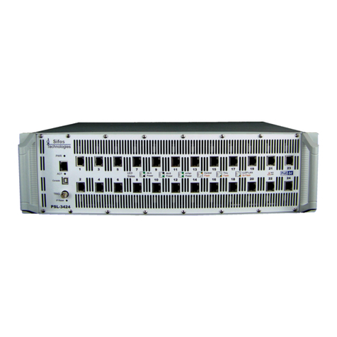
Sifos Technologies PSA-3000 User manual
Sifos Technologies
Sifos Technologies PowerSync PSA100-SA Product manual
Sifos Technologies
Sifos Technologies PowerSync PSA-3002-SA Product manual
Sifos Technologies
Sifos Technologies PowerSync PDA-300 User manual
Sifos Technologies
Sifos Technologies PhyView PVA-3000 User manual

Sifos Technologies
Sifos Technologies PowerSync PSA100 User manual


