Sifos Technologies PowerSync PSA-3002-SA Product manual

PowerSync Service Analyzer Reference Manual
June 12, 2017 Sifos Technologies page
1
Sifos Technologies
PowerSync Service Analyzer
PSA-3002-SA
Technical Reference
Manual
Version 4.2
Revised June 12, 2017
Copyright© 2013-2017 Sifos Technologies
®

PowerSync Service Analyzer Reference Manual
June 12, 2017 Sifos Technologies page
2
Disclaimer
The information contained in this manual is the property of Sifos Technologies, Inc., and is furnished for use by recipient
only for the purpose stated in the Software License Agreement accompanying the user documentation. Except as permitted
by such License Agreement, no part of this publication may be reproduced, stored in a retrieval system, or transmitted, in
any form or by any means, without the prior written permission of Sifos Technologies, Inc.
Information contained in the user documentation is subject to change without notice and does not represent a commitment
on the part of Sifos Technologies, Inc. Sifos Technologies, Inc. assumes no responsibility or liability for any errors or
inaccuracies that may appear in the user documentation.
Warrantee
Sifos Technologies Inc., warrants to recipient that hardware (“Hardware”) and the tangible media on which it supplies
Software will be free from significant defects in materials and workmanship for a period of 12 months from the date of
delivery (the “Warrantee Period”), under normal and intended use and conditions. Sifos also warrants that during the
Warranty Period, the Software that it supplies will operate substantially in accordance with the specifications supplied by
Sifos for such Software. Sifos does not warrant that the functions contained in the Software will meet a specific
requirement or that the operation will be uninterrupted or error free. Sifos shall have no warranty obligations whatsoever
with respect to any Software which has been modified in any manner by any third party.
Defective Product under warranty shall be, at Sifos’ discretion, repaired or replaced or a credit issued for an amount equal
to the price paid for such Product provided that: (a) such Product is returned to Sifos Technologies after first obtaining a
return authorization number and shipping instructions, freight prepaid, to Sifos’ location in the United States; (b) Recipient
provides an explanation of the defect or Software failure claimed; and (c) the claimed defect actually exists and was not
caused by fault, neglect, accident, misuse, improper storage, improper installation, improper repair (other than by Sifos or
its agents), fire, flood, lightning, power surges, earthquake or alteration (unless such alteration performed by Sifos or its
agents). Sifos will ship repaired Products to recipient, freight prepaid, within ten (10) working days after receipt of
defective Product. Except as otherwise stated, any claim on account of defective materials or for any other cause
whatsoever will conclusively be deemed waived by recipient unless written notice thereof is given to Sifos Technologies,
Inc. within the Warrantee Period. Product will be subject to Sifos Technologies’ standard tolerances for variations.
TO THE EXTENT PERMITTED BY APPLICABLE LAW, ALL IMPLIED WARRANTIES, INCLUDING BUT NOT
LIMITED TO IMPLIED WARRANTEES OF MERCHANTABILITY, NONINFRINGEMENT AND FITNESS FOR A
PARTICULAR PURPOSE, ARE HEREBY EXCLUDED, AND THE LIABILITY OF SIFOS, IF ANY FOR DAMAGES
RELATING TO ANY ALLEGEDLY DEFECTIVE PRODUCT SHALL BE LIMITED TO THE ACTUAL PRICE PAID
BY THE PURCHASER FOR SUCH PRODUCT. IN NO EVENT WILL SIFOS TECHNOLOGIES BE LIABLE FOR
COSTS OF PROCUREMENT OF SUBSTITUTE PRODUCTS OR SERVICES, LOST PROFITS, OR ANY SPECIAL
DIRECT, INDIRECT, CONSEQUENTIAL OR INCIDENTAL DAMAGES, HOWEVER CAUSED AND ON ANY
THEORY OF LIABILITY, ARISING IN ANY WAY OUT OF THE SALE AND/OR LICENSE OF PRODUCTS OR
SERVICES TO RECIPIENT EVEN IF ADVISED OF THE POSSIBILITY OF SUCH DAMAGES AND
NOTWITHSTANDING ANY FAILURE OF ESSENTIAL PURPOSE OF ANY LIMITED REMEDY.
Safety Precautions
To prevent electric shock, do not remove the cover of the PSA-3002-SA. No user serviceable parts are inside. Service
should be referred to qualified personnel.
The PSA-3002-SA is for connection only to the isolated intra-corporate or private Ethernet networks.
The PSA should be powered via the supplied AC Power Adapter, which includes an Earthing Conductor. The ground
terminal of the plug should not be modified, since this could result in a product that is not properly earthed. When placing
the equipment in its final configuration, the equipment should be placed such that it is easy to access the power cord; this
will allow the cord to be pulled out of the unit in the event that it is necessary to remove power. THE PSA-3002-SA
SHOULD ONLY BE OPERATED WITH THE POWER SUPPLY THAT WAS PROVIDED WITH THAT PRODUCT.
THERE ARE VENTILATION HOLES ON THE SIDES AND TOP OF THE PSA-3002-SA. THESE SHOULD NOT BE
BLOCKED OR OTHERWISE OBSTRUCTED.

PowerSync Service Analyzer Reference Manual
June 12, 2017 Sifos Technologies page
3
Table of Contents
1. Introduction ....................................................................................................................... 5
1.1. Hardware Installation and Setup Procedures..............................................................................................5
1.1.1. Host PC Requirements..............................................................................................................................5
1.1.2. Network Connection and Host Computer Considerations ..........................................................................6
1.1.3. Package Contents.....................................................................................................................................6
1.1.4. Powering Up PSA-3002 and PVA-3002 Compact Instruments...................................................................6
1.1.5. IP Address Set-Up via Console Port.........................................................................................................6
1.1.6. RS-232 Console Connections ...................................................................................................................6
1.1.7. Configuring Terminal Emulator and Setting IP Address.............................................................................7
1.1.1. IP Address Set-Up via PowerShell Tcl or Wish.........................................................................................7
1.1.2. DHCP Address Option...............................................................................................................................8
1.1.3. IP Address Factory Default Restoration.....................................................................................................8
1.1.4. Connecting the Ethernet Port ....................................................................................................................8
1.1.5. Test Port LED Indicators ...........................................................................................................................9
1.2. Software Installation & Initial Connection...................................................................................................9
1.2.1. Installing PSA Software onto Microsoft Windows.......................................................................................9
1.2.2. Tcl/Tk Installation Problems.......................................................................................................................9
1.2.3. Notepad++ Editor for PowerShell PSA Programming ................................................................................9
2. PoE Service Analyzer Tests and Operation.................................................................. 11
2.1. PoE Service Access Tests..........................................................................................................................11
2.2. Running the PoE Service Analyzer from PSA Interactive.........................................................................13
2.3. PoE Service Test Reporting .......................................................................................................................14
2.4. PoE Intermittent Service Detection............................................................................................................15
2.5. Visual PoE Analysis....................................................................................................................................15
2.6. Accessing the PoE Service Analyzer from PowerShell PSA....................................................................16
3. PoE and the PowerSync Analyzer................................................................................. 17
3.1. IEEE 802.3af / 802.3at Overview.................................................................................................................17
3.1.1. IEEE 802.3at Enhancements...................................................................................................................17
3.1.2. The Power Connection............................................................................................................................17
3.1.3. PD Detection...........................................................................................................................................18
3.1.4. PD Classification.....................................................................................................................................19
3.1.5. Power-Up................................................................................................................................................19
3.1.6. Power Removal.......................................................................................................................................20
3.1.7. 802.3at Type-2 (High) Power Capacity....................................................................................................20
3.1.8. 802.3at Backward Compatibility with 802.3af...........................................................................................20
3.1.9. 802.3at Gigabit-Capable PoE MidSpan PSE’s.........................................................................................21
3.1.10. Limiting Cost Increase for 802.3at High Power (Type-2) Links...............................................................21
3.1.11. 802.3at Improved Power Management Granularity................................................................................21
3.2. Power Sourcing Equipment –Specification Latitude...............................................................................21
3.2.1. Signaling Variations.................................................................................................................................21
3.2.2. Connection Alternatives...........................................................................................................................22
3.2.3. MPS Behaviors........................................................................................................................................22
3.2.4. Legacy Modes and Proprietary Detection Schemes ................................................................................22
3.3. System Hardware Overview .......................................................................................................................23
3.3.1. Port Switch and Detection Subsystem.....................................................................................................23
3.3.2. Triggers...................................................................................................................................................24
3.3.3. Static DC and Transient Loads................................................................................................................25
3.3.4. (Omitted).................................................................................................................................................26
3.3.5. DC Meters...............................................................................................................................................26
3.3.6. AC Meter.................................................................................................................................................26
3.3.7. Time Interval Meter .................................................................................................................................26
3.3.8. Layer 2 (LLDP Emulation) Subsystem.....................................................................................................26

PowerSync Service Analyzer Reference Manual
June 12, 2017 Sifos Technologies page
4
3.3.9. LAN Test OUTnPorts..............................................................................................................................26
3.4. System Software Overview.........................................................................................................................27
3.4.1. PowerSync Analyzer Configuration Files.................................................................................................27
3.4.2. Directory and File Organization –Microsoft Windows..............................................................................28
3.4.3. Directory and File Organization –Linux and Unix...................................................................................28
3.4.4. Tcl/Tk Requirements & Resources ..........................................................................................................29
3.5. (Section Omitted)........................................................................................................................................29
3.6. (Section Omitted)........................................................................................................................................29
3.7. PSA-3002-SA Technical Specifications.....................................................................................................30
3.7.1. LAN Interface Specifications....................................................................................................................30
3.7.2. PoE Port Connections.............................................................................................................................30
3.7.3. Detection and AC MPS Specifications.....................................................................................................30
3.7.4. Current Load Specifications.....................................................................................................................31
3.7.5. DC Metering Specifications .....................................................................................................................31
3.7.6. AC Metering Specifications......................................................................................................................32
3.7.7. Triggering Specifications .........................................................................................................................32
3.7.8. Time Interval Metering Specifications......................................................................................................32
3.7.9. (Omitted).................................................................................................................................................33
3.7.10. Front Panel PSA-3102 LED Indicators...................................................................................................33
3.7.11. Programming and Control......................................................................................................................33
3.7.12. Physical and Environmental ..................................................................................................................33
3.7.13. Certifications .........................................................................................................................................33

PowerSync Service Analyzer Reference Manual
June 12, 2017 Sifos Technologies page
5
1. Introduction
The PSA-3002-SA is a special adaptation of the PowerSync Analyzer (PSA), the network industry’s virtual standard
instrument for Power-Over-Ethernet (PoE) design validation and Power Sourcing Equipment (PSE) systems testing. The
PSA-3002-SA leverages the PSA-3002 “Compact” hardware platform and adds a specialized application aimed at
comprehensive qualification of PoE Service at the Powered Device (PD) interface. The PSA-3002-SA connects in place
of a PD to automatically analyze and report on all critical parameters of the PoE service including power capacity, power
management, and numerous interoperability parameters.
This manual provides a detailed overview of the PSA-3002-SA and is organized as follows:
Section 1 overviews installation and setup of PSA-3002-SA hardware and software.
Section 2 will discuss the PSA-3002-SA Service Analyzer automated test suite including Basic Service tests, Parametric
Interoperability tests, Classification Service tests, Line Monitoring tests, and signal viewing capabilities. It will also cover
operation of the PowerSync Service Analyzer from PSA Interactive and Powershell PSA.
Section 3 will review basic PoE technology, PSE product characteristics, and the hardware/software features of the
PowerSync Analyzer.
The PowerSync Analyzer family from Sifos Technologies also includes the following products:
PSA-3000: Chassis-based analyzer with capacity to test up to 24 PSE ports. The PSA-3000 fully supports optional
modules including the 802.3at PSE Conformance Test Suite and the PSE Multi-Port Suite. The PSA-3000
additionally offers robust 802.3at LLDP PD Emulation.
PSA-3048: The PSA-3048 “RackPack” bundles 48 test ports in 2 chassis’ with equivalent options and capabilities as
the PSA-3000.
PSA-3002: The PSA-3002 Compact is a 2-port, portable versions of the PSA-3000 optionally offering full support of
the PSE Conformance Test Suite. The PSA-3002 is fully software compatible with the PSA-3000 and PSA-3048
chassis-based platforms. The PSA-3000 additionally offers robust 802.3at LLDP PD emulation.
PSL-3000: The PSL-3000 (Programmable Load) is a low cost per-port version of the PSA-3000 aimed at PoE testing
in a production environment. The PSL-3000 supports the PSE Multi-Port Suite for the PSA-3000 and also supports
upward compatible automation scripting with the PSA family. The PSA-3000 additionally offers robust 802.3at
LLDP PD Emulation.
PDA-602A: The PDA-602A is a stand-alone analyzer for assessing 802.3at compliant Powered Devices (PD) and
their expected interoperability with a broad range of PSE’s. It is also useful for PD design analysis and parametric
reporting.
PVA-3000 & PVA-3002: The PhyView Analyzer is an innovative and highly automated solution for physical layer
evaluation of 10/100/1000Base-T interfaces. This instrument uses the same chassis and software platform as the
PSA-3000.
1.1. Hardware Installation and Setup Procedures
The PSA-3002-SA requires a host PC running PSA Software, connected to the PSA-3002-SA instrument over a LAN.
1.1.1. Host PC Requirements
IBM Compatible PC running Microsoft Windows 10, 8, 7, Vista, or XP.
Microsoft Excel 2016, 2013, 2010, or 2007 is required for standard report generation associated with the PSE
Conformance Test Suite, the PSE Multi-Port Test Suite, the PVA PHY Performance Test Suite, PSA/PVA-3000
Graphic Reports, and PSA-3000/PSL-3000 LLDP Protocol Reporting.
NOTE! Microsoft Excel must be configured to allow macros to run automatically or alternatively, to allow macros to
run from Sifos Reporting directories such as \Users\Public\Sifos\PSA1200\Results\ or \Program
Files\Sifos\PSA1200\Results\. Note that Excel may produce vague or misleading error messages such as “low
memory” when macros are not enabled! Use the Excel [File] [Options] [Trust Center] menu to enable macros.
NOTE! If installing Microsoft Office, perform that installation BEFORE installing PSA Software.
PSA software is also available for SUSE, RedHat (Fedora), and Debian Linux Workstations.
400MHz Pentium or higher recommended. Minimum 60MB Drive space and 512MB RAM required for PSA
Software.

PowerSync Service Analyzer Reference Manual
June 12, 2017 Sifos Technologies page
6
SVGA Color Monitor, Mouse, CD Rom Drive, and depending upon PSA-3000 Console Port, either USB 2.0 interface
or an RS232 serial port that supports hardware flow control.
10/100Base-T or 10/100/1000Base-T LAN interface –if direct connected to a PowerSync or PhyView instrument, a
crossover cable will be required if the PC LAN interface is not auto-MDI capable.
Tcl/Tk Version 8.4.5 –8.4.nn. (Tcl versions 8.5 and later are not officially supported by Sifos.) Tcl/Tk 8.4.20 is provided
as part of the Microsoft Windows installer application for PSA Software. Customers with Linux workstation hosts must
independently install Tcl/Tk prior to using PSA Software.
1.1.2. Network Connection and Host Computer Considerations
As is typical of most LAN controlled instruments, the PSA-3002-SA generally utilizes a fixed IP Address and therefore is
typically deployed on a private LAN network or connected directly to a PC. PC’s that will control these instruments
should have capability to reside on this private LAN using either a fixed IP Address or a carefully administered address
provisioning method that protects against address conflicts with instruments utilizing fixed IP addresses.
PC’s and workstations may host a second network connection via a separate LAN interface to a building or enterprise
network. In the event that a second LAN interface is utilized for wide area networking purposes, it is recommended that
the two LAN interfaces be kept completely separate with no route paths between them. See applicable PC and operating
system literature when configuring multiple LAN interfaces.
The network connection between host computer and instrument should not introduce significant delay or latency.
Network connection latencies exceeding 20 msec can adversely impact automated tests and utilities affiliated with the PSA
instrument. The host computer should be able to run PSA Software, particularly any automated tests and utilities, without
severe run-time process preemption that might manifest as LAN connection latency.
1.1.3. Package Contents
The PSA-3002-SA is shipped with the following items:
Dual test port “compact” instrument
PSA/PVA/PSL Software Installation CD
AC wall-mount power supply
CAT5e Ethernet cables, crossover and standard
RS232 Straight-through cable with DB9M to DB9F connections.
Installation and Technical Reference Manuals (paper and on CD)
1.1.4. Powering Up PSA-3002 and PVA-3002 Compact Instruments
Connect the supplied modular power supply to the 5VDC input in the rear of the instrument and then to a properly
grounded AC outlet (see “Safety Precautions”). If equipped, press the momentary power switch in the back of the chassis.
The test ports should all flash their LED’s for about 2 seconds. At this point, the instrument is available for all testing
operations.
NOTE! Use of a modular power supply other than the AC adapter furnished by Sifos is not recommended and may have
adverse consequences to either the test instrument and/or to measurement and testing results. Under no circumstances
should the GROUND connection on the modular power supply be removed or bypassed.
1.1.5. IP Address Set-Up via Console Port
The instrument is typically shipped from the factory with an IP Address of 192.168.221.105. Under typical situations, the
user may need to change this to an address that matches their local network settings.
Users may work with the Console port to re-configure IP address and IP mask bits. Console ports are RS-232 DB9
connections on the rear panel. The communication protocol is RS-232 and the Console port is treated as a Serial (“COM”)
port in the host PC. Terminal emulation software such as HyperTerminal may then be configured and used to communicate
from the host computer.
NOTE! The PowerSync instrument’s console port is available exclusively for IP Address set-up and PSA Controller
firmware updates. Under normal use it should be left disconnected.
1.1.6. RS-232 Console Connections
Connect a standard RS-232 cable with DB9 connectors (furnished with the instrument) from host PC to the PSA controller
in the back of the PSA-3002-SA.
Then configure the terminal emulator as described below.

PowerSync Service Analyzer Reference Manual
June 12, 2017 Sifos Technologies page
7
1.1.7. Configuring Terminal Emulator and Setting IP Address
The HyperTerminal terminal emulator is set-up is as follows:
Start HyperTerminal,
Select a connection name when prompted
In the connection dialog, enter the COM x port for Connect using
(see Figure 1.1). This is the RS-232 serial or virtual COM port in the host
PC.
In the Port Settings dialog, select the following parameters:
Bits per second > 9600
Data bits > 8
Parity > None
Stop bits > 1
Flow Control > Hardware
With HyperTerminal set up and running as described above, hit the ENTER
key on the Keyboard. The following menu will appear:
Type 1and press ENTER. Follow the command prompts to set up the IP address. Note that the IP mask is entered as a bit
count of 1’s where, for example, 255.255.255.0 is 24 ‘1’ bits..
There is approximately a 10-second delay before “Done” is displayed, and then the main menu appears again.
Type “3” to Enable the PSA. Then disconnect the serial port and close the terminal emulation software.
NOTE! The PSA LAN interface will not operate if the serial port to the PSA is open and the command menu is visible as a
result of pressing the ENTER key.
1.1.8. IP Address Set-Up via PowerShell Tcl or Wish
To alter the default IP address to another fixed address, users may use PowerShell Wish or PowerShell Tcl to connect to
192.168.221.105, then use the psa_setipaddress command (see command syntax below) in PowerShell Wish or Tcl to alter
the address and IP mask to another setup. This method of configuring IP address avoids the need to interface to the
Console port, however, care must be taken to change the address and mask to one that is compatible with the host PC’s
>1
Use DHCP ? (Y/N)> N
Enter IP Address (xxx.xxx.xxx.xxx) > 10.10.10.114
Confirm? (Y/N) y
Enter Number of Mask Bits (01 –30) > 24
255.255.255.0
Confirm? (Y/N) y
Enter Gateway Address (xxx.xxx.xxx.xxx) > 10.10.10.1
Confirm? (Y/N) y
Please Wait... Done
PowerSync Analyzer
Firmware Version #.##
MAC Address: 00204A######
IP Address: 192.168.221.105
Mask: 255.255.255.0
Gateway: 192.168.1.1
1. Set IP Address
2. Firmware Upgrade (Controller)
3. Enable PSA
(PSA DISABLED) >
Figure 1.1. Console Connection

PowerSync Service Analyzer Reference Manual
June 12, 2017 Sifos Technologies page
8
subnet. For example, if the subnet mask is 255.255.255.0, then the new IP address must remain in the 192.168.221.***
subnet. This will enable re-connection to the new IP address after the change is made.
NOTE! Once you have changed the IP Address in PowerShell, you will need to use the PowerShell psa command to re-
connect PowerShell PSA to the instrument at its new IP address.
Command
Command Parameters
Query
Returned
Parameters
psa
ipAddress
?
Current Chassis IP
Address
Selects the instrument to which subsequent commands and
queries will be directed.
ipAddress An n.n.n.n format IP address. This address will
apply until re-established by another psa command and is
persistent if the shell is closed and re-opened.
psa_setipaddress
ipaddress <mask mask> <gateway gateway>
Current IP Address,
Mask, and Gateway
Address.
Installs a new fixed IP address to be utilized by the Chassis Controller.
This command takes about 15 seconds to execute but does not require
rebooting of the PSA chassis for the new address to take affect.
ipaddress is the new IP address that will be utilized by the Chassis
Controller in the format of nnn.nnn.nnn.nnn.
mask keyword indicating that next item is IP address mask.
mask is the IP mask to be utilized for Internet communications. Format
is nnn.nnn.nnn.nnn. Default is 255.255.255.0 (Class C). Must
comply with IP rules for valid mask values.
gateway keyword indicating that next item is IP gateway address.
gateway is a gateway address to be utilized for Internet Protocol.
Format is nnn.nnn.nnn.nnn. Default is 000.000.000.000.
psa_version
Outputs current version of PowerShell PSA software components.
1.1.9. DHCP Address Option
When configuring an IP address, if DHCP is selected, the PSA will attempt to acquire an address from a network DHCP
server. Generally, this configuration is not advised for test laboratory environments where most instruments operate with
hard-coded addresses. Knowledge of the PSA address is critical in order to connect and control the PSA from PSA
Interactive or PowerShell, so if DHCP is utilized, the assigned address must be known and must be stable over the course
of instrument usage. The PSA console menu will display the acquired address if the DHCP request is successful.
If the Controller is unable to obtain an address, a message such as “No response to DHCP request” will be displayed. At
this point, you have the option of trying DHCP again, or configuring a static IP address.
NOTE! The PSA must have a valid IP address in order to be accessed by PowerShell.
1.1.10. IP Address Factory Default Restoration
PSA-3002-SA instruments equipped with an On/Off power switch on the rear panel can reset IP address to the factory
default address 192.168.221.105 as follows: Turn power on to the instrument, then depress the On/Off switch continuously
for a period of 20 seconds or more. This will result in a flashing of the LED power indicator that indicates the restoration of
the original factory set address. PowerShell PSA can then be utilized to connect to the instrument at the factory default
address and then to modify that address using the psa_setipaddress command in PowerShell PSA.
1.1.11. Connecting the Ethernet Port
The Ethernet Port on the instrument can be connected to any 10/100/1000BaseT Ethernet Switch or Hub. Connections to a
Hub or Switch will require a standard CAT5 (or better) UTP patch cable.
The Ethernet Port on the instrument can also be connected directly to a host PC. When connecting an instrument that has
the factory default IP address directly to a PC, the PC TCP/IP networking properties must initially include a
192.168.221.xxx fixed IP address with subnet mask bits 255.255.255.0. Direct Connections to a PC may require the
CAT5e Ethernet crossover cable if the PC LAN interface does not support auto-MDI.
If the instrument is to be used in a networking environment with multiple subnets, the host PC must be able to access the
subnet that the instrument is on, in order to communicate with it. If the instrument is located on a different subnet from the
PC, the routing table in the PC must describe how to route to that subnet (and a gateway must exist between the subnets).

PowerSync Service Analyzer Reference Manual
June 12, 2017 Sifos Technologies page
9
1.1.12. Test Port LED Indicators
Each test port generally includes 4 LED indicators. The purpose and function of each of these indicators is described in
Section 3.7.10.
1.2. Software Installation & Initial Connection
1.2.1. Installing PSA Software onto Microsoft Windows
Put the PSA-3002-SA Installation CD in the drive and wait for the installation
wizard to open up. The PSA software installer, PSA_Installer_#.#.#.exe, should
automatically run. (#_#_# is the PSA software version number.)
1. Click Install. If Tcl/Tk is not installed, a Tcl/Tk 8.4 dialog box will appear so
that Tcl 8.4.20 can be installed (see Figure 1.2). Tcl/Tk must be installed in
order for PSA software to operate. PSA software requires Tcl 8.4.5 or newer
and is not officially supported with Tcl 8.5 or newer. This dialog will
appear if a Tcl version between 8.4.5 and 8.5 is not found on the host
computer. If Tcl/Tk software is installed, it will be placed in either
c:\Program Files (x86)\tcl8.4.20\ or c:\Program Files\tcl8.4.20\ depending
upon Windows OS version.
2. Once Tcl/Tk 8.4 is either located or installed, PSA Software will be installed
(see Figure 1.3). If an older version of PSA software already exists on
the host computer, the current version will still be installed to replace
that older version. Generally, all program files associated with PSA
Software are placed in either c:\Program Files (x86)\Sifos\PSA1200\ or
c:\Program Files\Sifos\PSA1200\ while data files and user-modifiable
files are placed in accordance with Section 3.4.2 below. Upon
completion, the notification of
Figure 1.4 will appear.
1.2.2. Tcl/Tk Installation Problems
If the PSA Software Installer discovers a non-supported version of Tcl/Tk on the host computer, it will abort the
installation of PSA software and offer the option to run the PSA Software Installer from the Windows “Run” command line
with an option that forces Tcl/Tk 8.4.20 installation and preempts other versions of Tcl/Tk already on the host. This action
could adversely impact another application that relies on Tcl/Tk. The command is: PSA_Installer_#.#.#.exe
ForceTCLInstall=1
Sifos Technologies has determined that certain CAD software packages in the market will install proprietary versions of
Tcl/Tk that are not compatible with PSA software. If conflicts arise with the Tcl/Tk installation, the above command line
installation procedure should be attempted. If that does not resolve the issue, contact Sifos Support for further guidance.
1.2.3. Notepad++ Editor for PowerShell PSA Programming
PowerShell PSA automated testing scripts may be created and edited in the freely available Notepad++ source code editor
that is readily available on the web (e.g. https://notepad-plus-plus.org). This powerful editor is knowledgeable of Tcl/Tk
and PowerShell PSA commands, global variables, and other common syntactical constructs such as braces and brackets,
math operators, etc. It provides many powerful capabilities that support authoring and troubleshooting bug-free scripts.
To configure Notepad++ for PowerShell PSA, first install Notepad++, then use the Language drop-down menu to Define
Your Language…, then select the Import control and import the file PowerShell_PSA.xml from the installed directory
for PSA software. This will typically be either c:\Program Files (x86)\Sifos\PSA1200\ or c:\Program
Files\Sifos\PSA1200\ depending upon Microsoft Windows OS version.
Figure 1.2. Tcl/Tk Installation
Figure 1.3. PSA Software Installation
Figure 1.4. Installation Complete

PowerSync Service Analyzer Reference Manual
June 12, 2017 Sifos Technologies page
10

PowerSync Service Analyzer Reference Manual
June 12, 2017 Sifos Technologies page
11
2. PoE Service Analyzer Tests and Operation
The primary component of the PowerSync PoE Service Analyzer is an automated test application for assessing PoE Service
to a PD. This application configures each PSA test port to function as a highly sophisticated service analyzer at the PD
interface (or service outlet). The analysis performed by the PoE Service Analyzer application is far more comprehensive
than PoE service measurements typically performed by commercially available hand-held service analyzers.
The PoE Service Analyzer application is accessible through PSA Interactive or PowerShell. This section will introduce
the types of testing performed by the PoE Service Analyzer and the associated reporting available.
2.1. PoE Service Access Tests
The PoE Service Analyzer combines PowerSync Analyzer test ports with specialized application software to enable the
most comprehensive and fully automated testing available for PoE analysis and qualification at a Powered Device service
access point. The PoE Service Analyzer assesses a wide range of interoperability risks, safety hazards, and PoE
performance limitations at the connection to any Powered Device.
The PoE Service Analyzer provides fully automated testing in 3 categories:
2.1.1. Basic Service Tests
Basic Service Tests evaluate the basic Power-over-Ethernet connection, reporting connection information such as powered
pairs (including multiple PoE sources), power polarity, PD disconnect detection method, and service category.
Parameter
Outcome
Explanation
Service Pairs &
Polarity
CONNECTION: ALT-A: MDI, MDI-X, NONE
CONNECTION: ALT-B: MDI, MDI-X, NONE
PoE service is active on ALT-A and/or ALT-B
pairset with polarity MDI or MDI-X.
CONNECTION: NONE
PoE service is not available
Disconnect
Detection
MPS: DC
PSE removes power when DC current below 5
mA.
MPS: AC
PSE removes power when PD 25Ksignature is
removed.
Service Category
TYPE-1
PoE service up to 13W
SUB_TYPE-1
PoE service between 4W & 7W
TYPE-2_PHY
PoE service up to 25.5W to any Class 4 PD
TYPE-2_LLDP
PoE service up to 25.5W provided Class 4 PD
supports PoE LLDP
TYPE-2_OTHER
PoE service up to 25.5W to any PD
DISABLED
No PoE service available
2.1.2. Parmeteric Tests
Parametric Tests report a number of parameters of the PoE service that are relevant to interoperability of all PD’s at the
PoE service outlet. Additionally, certain safety related behaviors of the PoE service are analyzed. Information collected
includes line voltages (DC and AC) at power extremes, detection signature range verification, rejection signature range
verification, inrush and overload tolerance of the PoE connection, disconnect timing, and overload timing response of the
PoE connection. In performing these tests, the PowerSyncAnalyzer is utilized to emulate a wide range of IEEE 802.3af
compliant steady state and transient Powered Device behaviors.
Parameter
Description
Range of Outcomes
MIN_DETECT:
Power Applied to Valid Low-End PD Signature
to assure all Valid PD’s are detected properly (24 K
)
PASS / FAIL
MID_DETECT
Power Applied to Nominal IEEE 802.3 Signature
to assure nominal 802.3at PD’s are detected properly (25 K
)
IEEE_Service /
No_IEEE_Service
MAX_DETECT:
Power Applied to Valid High-End PD Signature
to assure all Valid PD’s are detected properly (26 K
)
PASS / FAIL
Non802_DET:
Power Applied to Capacitive Load, Invalid 802.3at PD
to note capability of PSE to power many “legacy” PD’s
Legacy_Det /
No_Legacy_Det
Full_Pwr_Time:
Time from PD Connection until PD Can Draw Full Power
0 –60 seconds
LLDP_Allocation:
Power Allocation from a Type-2, LLDP PSE
X.Y Watts / N/A
DCV_Min_Load:
PoE Line Voltage to Very Low Power PD
to assure valid line voltage to low power PD
(Type-1 PSE: 37 to 57 VDC, Type-2 PSE: 42.5 to 57 VDC)
0 –60 VDC
PASS / FAIL

PowerSync Service Analyzer Reference Manual
June 12, 2017 Sifos Technologies page
12
Parameter
Description
Range of Outcomes
ACV_Min_Load:
PoE Line Noise to Very Low Power PD
to assure “clean” DC line voltage to low power PD (≤ 0.5 Vpp)
0 –1 Vpkpk
PASS / FAIL
DCV_Max_Load:
PoE Line Voltage to High Power PD
to assure valid line voltage to high power PD
(Type-1 PSE: 37 to 57 VDC, Type-2 PSE: 42.5 to 57 VDC)
0 –60 VDC
PASS / FAIL
ACV_Max_Load:
PoE Line Noise to High Power PD
to assure “clean” DC line voltage to high power PD (≤0.5 Vpp)
0 –1 Vpkpk
PASS / FAIL
Overload_Tolerance:
Tolerance of Service to Maximum Transient Overload
to assure power maintained to compliant PD’s (Type-1 PD:
≥400mA for ≥45msec, Type-2 PD: ≥684mA for ≥45 msec)
PASS / FAIL
PD_Disconnect:
Power Removal Timing on PD Disconnect
to assure PoE service will not damage non-PD’s (≤500 msec)
0 to 1500 msec
PASS / FAIL
Inrush_Tolerance:
Tolerance of Service to Worst Case Allowable Startup Load
to assure proper startup of all compliant PD’s
(≥450 mA for ≥45 msec)
PASS / FAIL / N/A
Overload_Shutdown:
Power Removal Timing on PD Overload Shutdown
to assure PoE Service will tolerate short duration power peaks and
not damage cables and connections (50 –75 msec with Type-1
PSE: ≥402 mA, Type-2 PSE: ≥684 mA)
0 to 1500 msec
PASS / FAIL / N/A
Min_Reject:
Rejection of Invalid Low-End PD Signature
to assure that non-PoE devices do not get powered (≤15 K
)
PASS / FAIL / N/A
Max_Reject:
Rejection of Invalid High-End PD Signature
to assure that non-PoE devices do not get powered (≥33 K
)
PASS / FAIL / N/A
Cap_Reject:
Rejection of Highly Capacitive PD Signature
to assure that non-PoE devices do not get powered
PASS / FAIL / N/A
2.1.3. Classification Service Tests
Classification Service Tests report the behavior of the PoE service connection to each PD classification (0, 1, 2, 3, or 4).
Information reported includes maximum power capacity available by PD classification as well as the ability of the PoE
connection to deliver the appropriate power capacity to PD classification signatures that are borderline for each PD
classification.
Parameter
Description
Range of Outcomes
Class_0_Capacity:
Power Available to a nominal PD Classifying as Class 0
to assure a minimum of 13 watts is available to PD
1 to 15 Watts
PASS / FAIL
Class_1_Capacity:
Power Available to a nominal PD Classifying as Class 1
to assure a minimum of 3.84 watts is available to PD
1 to 15 Watts
PASS / FAIL
Class_2_Capacity:
Power Available to a nominal PD Classifying as Class 2
to assure a minimum of 6.49 watts is available to PD
1 to 15 Watts
PASS / FAIL
Class_3_Capacity:
Power Available to a nominal PD Classifying as Class 3
to assure a minimum of 13 watts is available to PD
1 to 15 Watts
PASS / FAIL
Class_4_Capacity:
Power Available to a nominal PD Classifying as Class 4
to assure a minimum of 25.5 watts is available to PD
12 to 37 Watts
PASS / FAIL
Class_0_Interop:
Power Available to PD with Borderline Class 0 Signatures
to assure all Class 0 PD’s receive the same power allocation
PASS / FAIL
Class_1_Interop:
Power Available to PD with Borderline Class 1 Signatures
to assure all Class 1 PD’s receive the same power allocation
PASS / FAIL
Class_2_Interop:
Power Available to PD with Borderline Class 2 Signatures
to assure all Class 2 PD’s receive the same power allocation
PASS / FAIL
Class_3_Interop:
Power Available to PD with Borderline Class 3 Signatures
to assure all Class 3 PD’s receive the same power allocation
PASS / FAIL
Class_4_Interop:
Power Available to PD with Borderline Class 4 Signatures
to assure all Class 4 PD’s receive the same power allocation
PASS / FAIL

PowerSync Service Analyzer Reference Manual
June 12, 2017 Sifos Technologies page
13
By the IEEE 802.3at standard, PD’s are classified by power utilization according to the table below. PD’s are responsible
for “signaling” this classification prior to receiving power from the PoE enabled network connection.
Classification
PD Maximum Power Requirement
0
0.44 to 13.0 Watts
1
0.44 to 3.84 Watts
2
3.85 to 6.49 Watts
3
6.49 to 13.0 Watts
4
13.0 to 25.5 Watts
2.2. Running the PoE Service Analyzer from PSA Interactive
PSA Interactive will open the PoE Service Analyzer to a PSA Connection Dialog (see
Figure 2.1). This dialog may be used to:
1) Connect to previously utilized analyzer
2) Select and Connect to a different analyzer (IP address)
3) Add, then Select, then Connect to a new analyzer (IP address)
When the PoE Service Test menu opens (see Figure 2.2), the presently connected PSA
IP address is displayed along with Test Slot and Test Port controls. In a PSA-3002-
SA, there is just one Test Slot and on all instruments there are two Test Ports that can
be selected. Test Port arrow buttons allow selection of Test Port 1 or Test Port 2.
The PoE Service Test
application consists of the three categories described earlier
in section 2.1: Basic Service, Parametric tests, and Class
Service analysis.
Selecting All Tests causes all three categories to run. This
setting is a requirement to produce the standard spreadsheet
report described in section 2.3 below.
Once the Service Test is configured, pressing the Run Test
button will cause the testing to start. As testing proceeds,
parameters are posted to the results display. Upon
completion of the testing, menu controls are re-enabled and
all results are displayed (see Figure 2.3). If All Tests was
selected, the Excel Report button will be enabled and may be
used to produce the standard test report shown in section 2.3.
Test results may also be stored in an ascii text file that will be
named for according to time and date by pressing the Save
Result button. This feature is available if any portion of the
Service Test is run.
The PoE Service Test menu also provides for two other types
of analysis of PoE service. The Line Monitor and Scope
Trace features are described in sections 2.4 and 2.5 below.
Figure 2.2 PoE Service Test Menu
Figure 2.3 Completed Service Test
Figure 2.1 Connection Dialog
PowerSync Service Analyzer Reference Manual
June 12, 2017 Sifos Technologies page
14
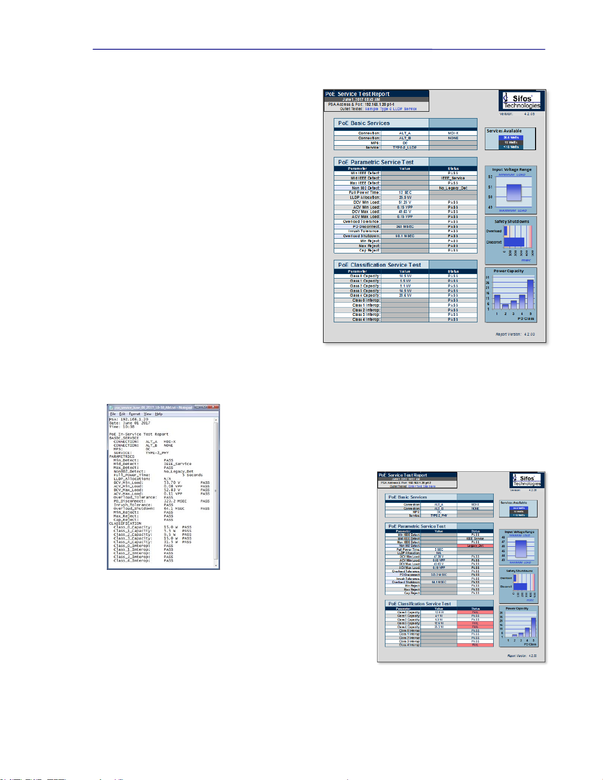
2.3. PoE Service Test Reporting
The Sifos PoE Service Analyzer includes a colorful
Microsoft Excel Test Report*(see Figure 2.4) that can
be automatically produced upon completion of the full set
of PoE Service Access Tests. In order to produce this
report, the full sequence of Service Tests must be
completed.
The report header provides the time and date of the
testing performed and enables user entry of the test site or
outlet location.
The report provides three tabular tables that include
results from PoE Basic Services, PoE Parameteric
Service testing, and PoE Classification Service analysis.
Parameters that should comply to the IEEE 802.3at PoE
system specification are notated with PASS/FAIL
indications in these tables.
The Services Available graphic indicates the level of
PoE service available, that is, 25.5W (Class 4), 13W
(Class 3), or <13W (Class 1 or 2). This is based upon
PSE capability.
A second graph, Input Voltage Range, depicts the PD
supply voltage range as a function of PD load power.
PD’s should receive a minimum of 37V if PSE provides
Class 0-3 service and 42.5V if the PSE provides Class 4
service.
The Safety Shutdowns graph shows the timing of power
removal both in response to a PD disconnect and to a PD power surge or overload. Service should be removed between
300msec and 400msec when a PD is disconnected and between 50msec and 75msec when an overload event occurs.
The Power Capacity graph charts the power available to various PD classifications.
The PD Maximum Power Requirements are provided in section 3.1.4.
Text reports (see Figure 2.5) may be produced when running all or any subset of the PoE
Service Access Tests. These reports are also time-date stamped and carry much of the
same information included in the spreadsheet report.
Actual test data and test reports are
retained in a Results directory on the
host PC. Typically, the directory path
will include \Results\ and is located
under \Users\Public\Sifos\PSA1200\
on Windows 10, 8, 7, and Vista
computers. On Windows XP
computers, the directory path is
\Program Files\Sifos\PSA1200\.See
section 3.4.2 for further information
on file directory locations.
Figure 2.6 depicts a non-compliant, or
marginally interoperable PoE service. This service indicates support for
non-802.3at PD types, a feature that might possibly damage non-PD
equipment. Additionally, the report indicates a power deficiency for
Class 0, 3, and 4 PD’s along with an inconsistent classification process
with all possible Class 4 signatures. These characteristics may not
interfere with the operation of many PD’s so the consequence is
therefore somewhat unpredictable, that is, it is very dependent on the
device that is connected to the service.
Figure 2.4 PoE Service Spreadsheet Report Depicting a Fully
Interoperable Class 4 PoE Service
*Requires Microsoft Excel 2007 or newer. Reports require the macro security in Excel be disabled for the Service
Report (service_report.xlsm) template file.
Figure 2.5 PoE Service Text
File Report
Figure 2.6 PoE Service Spreadsheet Report,
Non-Compliant Service

PowerSync Service Analyzer Reference Manual
June 12, 2017 Sifos Technologies page
15
2.4. PoE Intermittent Service Detection
The PoE Service Analyzer also includes an automated Line Monitor
designed to capture intermittent service drop-outs. This test may be
configured to run with PD Class 1, Class 2, Class 3, or Class 4
emulation, including Class 4 with LLDP. Users select between a 30
minute test and a 12 hour test, though in either case, users have the
option to terminate monitoring at any time and recover results. In
Figure 2.7, the Line Monitor is run for 30 minutes on a Class 4 LLDP
service with no interruptions to a 25W load, then run again on a
different Class 3 service using a 12.9W load with several interruptions
recorded as it runs.
Intermittent Service Detection is sensitive to power drops that are
either instantaneous or of longer durations. The test will report a
count of observed drops as well as the elapsed time until the first
observed service drop-out.
Testing for intermittent PoE service at any test site or outlet can be
beneficial both for assessing intermittent connections and for capturing
PSE behaviors at a particular outlet when power demands or other
intermittent transitions are exceeding total output power capacity across a
range of PoE served devices. Line Monitor Test Reports can be saved to a
time-date stamped text file (see Figure 2.8) upon test completion.
2.5. Visual PoE Analysis
Another unique feature of the Sifos PoE Service Analyzer is the ability to produce graphical waveforms of controlled
PoE events. These waveforms can be useful for troubleshooting problem behaviors.
Two Power-Cycle waveforms (see Figure 2.9) are included to observe the full cycle of an ordinary PoE power-up and PD
disconnect power-down captured over a 5 second time interval. One waveform looks at line voltage while the other
records electrical current flow. Both can be configured to run with PD Class 1, Class 2, Class 3, or Class 4 emulation,
including Class 4 with LLDP. Users with a moderate understanding of PoE technology can observe and analyze
detection signaling, classification signaling, the powered line state, and PSE response to a PD disconnect.
Figure 2.7 PoE Service Line Monitor
Figure 2.8 PoE Line Monitor Report
Figure 2.9 PoE Service Analyzer Waveforms

PowerSync Service Analyzer Reference Manual
June 12, 2017 Sifos Technologies page
16
Two additional waveforms available are Disconnect Shutdown and
Overload Shutdown (see Figure 2.9). These waveforms may utilized
to visualize the PD service outlet response to either a PD disconnect or a
PD transient overload condition. Both conditions should result in power
removal in order to prevent damage to network devices when plugged
into the service outlet. The disconnect shutdown should occur in
approximately a half second while the overload shutdown should occur
in less than one tenth of a second, regardless of PD Classification
selected.
Following waveform capture, waveforms may be printed or imported to
Microsoft Excel for further analysis as shown in Figure 2.10.
2.6. Accessing the PoE Service Analyzer from PowerShell PSA
The automated tests for PoE Service and Service Monitoring may also be accessed using commands from PowerShell TCL
or PowerShell Wish. These tests do not require any kind of pre-configuration of the PSA test port to the type of PSE
servicing the PoE interface. The tests will automatically scan for powered pairs and power polarity.
Utilizing PowerShell can be a significant automation advantage when the PoE Service or Service Monitoring tests are to be
automatically run in succession across one or more service outlets without user intervention.
Command
Command Parameters
psa_poe_service
<slot,port> <basic | parm | class | all <-s>> <-f> <-v>
Executes the PoE Service Test application according to user configuration. This test will
automatically deliver a spreadsheet report if “all” tests are specified along with the
appropriate reporting option.
<slot,port> Specifies the PSA test port. Default is current slot and port.
basic Run only the Basic PoE Service Tests described in Section 2.1.
parm Run only the Parametric PoE Service Tests described in Section 2.1.
class Run only the Classification Integrity PoE Service Tests described in Section 2.1.
all Run all (basic, parametric, and classification integrity) Tests described in Section
2.1. This is the default mode and must be utilized to generate the spreadsheet report
described in Section 2.3.
-s Control to produce spreadsheet report shown in Section 2.3.
-f Control to produce a time-date named text file test report. This can be specified
whether running all Service Tests or only a subset of Service Tests.
-v Control to run the PoE Service Test in a “verbose” diagnostic mode.
psa_poe_monitor
<slot,port> <1| 2| 3> <short | long> <-f>
Executes the PoE Service Monitor to capture and report on intermittent PoE Service
drops.
<slot,port> Specifies the PSA test port. Default is current slot and port.
1 Runs the Service Monitor using a Class 1 PD and associated power load.
2 Runs the Service Monitor using a Class 2 PD and associated power load.
3Runs the Service Monitor using a Class 3 PD and associated power load.
short Specifies to run the Service Monitor over a 30 minute period. This is the default.
long Specifies to run the Service Monitor over a 12 hour period.
-f Control to request a time-date named text file report be generated upon completion of
the testing.
A much more comprehensive discussion of PowerShell PSA is provided in section 4 of the PSA-3000 Technical
Reference Manual provided with the PSA-3000 and PSA-3002 PowerSync Analyzers. Users wishing to create automated
testing applications involving the PSA-3002-SA should consult that manual.
Figure 2.10 Voltage Cycle Waveform - Excel

PowerSync Service Analyzer Reference Manual
June 12, 2017 Sifos Technologies page
17
3. PoE and the PowerSync Analyzer
This section is provided to those wishing to get a deeper understanding of PoE technology and/or gain better insight into
the PSA-3002 PowerSync Analyzer that provides the hardware/firmware platform for the PSA-3002-SA Service Analyzer.
3.1. IEEE 802.3af / 802.3at Overview
The 802.3af specification was originally designed to create an environment whereby Powered Devices (PD’s) from
numerous different manufacturers could be interconnected to Power Sourcing inter-networking equipment (PSE) including
switches, routers, and hubs produced by many different networking equipment manufacturers. It is envisioned that such
interoperability will lead to lower cost and higher proliferation among both the sourcing equipment and the networked
PD’s. The ongoing emergence of VoIP telephony combined with ramp-up in TCP-IP networked devices show that this is
a fast growing market. There are numerous new PD functions such as security, inventory management, environmental
management, and other applications.
The basic features of 802.3af PoE were:
48V DC Supply to PD’s
Guaranteed 13 Watts of Power Consumption per network connection (PD and cabling)
Power Sourcing from both “End-Point” switches/routers as well as “Mid-Span” power “adder” devices.
Safety “interlocks” to prevent powering when no PD’s are connected and to assure prompt power removal when PD’s
are disconnected as well as to limit DC current flow at all voltage levels.
Physical layer mechanism for PSE’s to characterize power demands of individual PD’s and thus manage power
delivered per port.
3.1.1. IEEE 802.3at Enhancements
The 802.3at specification both replaces and expands upon 802.3af is several key areas:
Enable higher power PD’s such as wireless access points, panning security cameras, video phones, and audio
appliances requiring continuous power to 25.5 watts up to 100M from the PSE. High Power PSE’s must furnish at
least 30.0 Watts at the PSE port.
Provide full backward compatibility and interoperability to existing 802.3af compliant PSE’s and PD’s.
Enable Midspan PSE’s to support 1000BaseT connections.
Restrict cost increases for PSE ports and PD equipment in areas such as PSE controller devices and PoE capable
magnetics such that PoE+ (high power) could become ubiquitous.
Improve potential power management granularity and power budgeting capability over time.
Resolve well known issues of specification clarity inherent in the 802.3af specification.
802.3at defines all PSE’s as either Type-1 or Type-2. Any PSE developed strictly to the original IEEE 802.3af
specification will be a Type-1 PSE. PSE’s that deliver at least 30 Watts per port must be Type-2 PSE’s. Many of the
802.3at specifications are divided according to Type-1 versus Type-2 PSE’s. However, 802.3at allows Type-1 PSE’s to
evolve in ways that gain many of the IEEE 802.3at feature enhancements described above even if they continue to limit
minimum output power to the 15.4 watt range.
Changes and enhancements introduced by 802.3at are the subject of sections 3.1.7 to 3.1.11 below.
3.1.2. The Power Connection
Under the 802.3at specification, DC power must be carried on 2 of the 4 pairs of a LAN (e.g. category 5) cable. DC
voltage is carried on one cabling pair (common mode) and reference (zero volts) is carried on a second cabling pair. ALT
A(alternative A) refers to the case where power is sourced on Pairs 2 and 3 (referring to EIA/TIA 568B), the data
transmission pairs for 10/100BaseT. ALT B refers to the case where power is carried on Pairs 1 and 4 that are otherwise
unused in 10/100BaseT.
Under 802.3af, Mid-Span PSE’s MUST apply power on the ALT B pairs while End-Span PSE’s may use either, though
typically will use ALT A. This allows both End-Span and Mid-Span PSE’s to coexist on the same cable.
Under 802.3at, Mid-Span PSE’s were redefined to enable 1000BaseT LAN links, and therefore were forced to add
magnetics in order to insert DC Power. With this change, Mid-Span PSE’s may apply power on either the ALT A or ALT
Bpairs.

PowerSync Service Analyzer Reference Manual
June 12, 2017 Sifos Technologies page
18
Power may be applied by and End-Span PSE in either an MDI or MDI-X (crossover) port configuration. This means that
from the PD’s point of view, the incoming voltage may look either like Positive or Negative polarity since in the latter
configuration, pairs 2 and 3 (as well as 1 and 4) are crossed. PD’s are required to be completely insensitive to whether
power is furnished on the ALT A or ALT B pairs and whether power is positive polarity or negative polarity.
In all cases, Mid-Span PSE’s must apply power in the positive (or MDI) polarity.
Each PSE port is responsible for managing 4 basic aspects (or phases) of PoE:
1. PD Detection
2. PD Classification
3. Power-Up
4. Power-Removal
3.1.3. PD Detection
A PoE enabled PSE port provides a low power signaling mechanism that constantly monitors for an 802.3at compatible
Powered Device (PD) to appear at the end of the LAN cable. If a non-powered network device is connected, the PSE port
can function just as would a non-PoE port and link to the networked device. However, if an 802.3 PD is connected, the
PSE port will quickly recognize this and begin the process of powering up the PD.
The primary means of detection is a measurement of PD
port electrical resistance performed by the PSE port.
802.3at specifies that compliant PDs will present a load
resistance at the PSE between 19 Kand 26.5 Kgiven
an input voltage under 10 VDC. It further specifies that
the method of resistance measurement shall allow for an
unknown voltage drop up to 2.8 volts associated with one
or more diode junctions in series with this load resistance.
This implies that “AC” resistance must be determined
from a [V / I] measurement performed at 2 (or more)
voltage levels and that the minimum detection voltage
must be at least 2.8 VDC.
Some of the relevant specifications affecting the detection
process are:
Characteristic
Minimum
Maximum
Units
Unterminated (Open Circuit) Detection Voltage
30
VDC
Terminated Detection Voltages
2.8
10
VDC
Detection Current Limit (compliance)
5
mA
[V / I ] Voltage Step
1
7.2
VDC
Maximum Acceptable Load Resistance
26.5
33
K
Minimum Acceptable Load Resistance
15
19
K
Maximum Acceptable Load Capacitance
0.15
10
F
Slew Rate of Voltage Step
0.1
V / sec
Detection Duration
500
mSec
Detection Backoff (following unsuccessful detection)
(does not apply to End-Span PSE’s)
2
Sec
It should be noted that despite the various requirements described for PD Detection signaling in the 802.3 specification, that
there is considerable room for design variation and that in practice, detection pulses and detection measurement schemes do
vary significantly across PSE interface technologies. The 802.3at standard does not prohibit the use of complementary
schemes that might improve detection accuracy and speed while also reducing risk of possible damage to non-PoE capable
end station equipment.
Figure 3.1 802.3at Detection

PowerSync Service Analyzer Reference Manual
June 12, 2017 Sifos Technologies page
19
3.1.4. PD Classification
IEEE 802.3at allows for PD’s to communicate their power demands to a PSE port via a “Classification” process. From the
perspective of a PSE port, PD’s can be classified as follows:
PSE Type
Classification
Guaranteed Power
at PSE Output
Guaranteed Power
at PD Input
Units
Type-1
Class 0
~15.4
13.0
Watts
Class 1
~4.0
3.84
Class 2
~7.0
6.49
Class 3
~15.4
13.0
Type-2
Class 4
30.0
25.5
A Type-1 PSE has the option not to classify the PD in which case the PD must be assumed to require Class 0 power.
Classification is performed by applying a voltage in the band from 15.5V to 20.5V and measuring the fixed DC current
load presented by the PD. The magnitude of measured current is then translated into a classification as follows:
Minimum Current
Maximum Current
Units
Classification
PD Type
0
5
mA
Class 0
Type-1
8
13
mA
Class 1
Type-1
16
21
mA
Class 2
Type-1
25
31
mA
Class 3
Type-1
35
45
mA
Class 4
Type-2
The PSE is free to make decisions regarding current
measurements that fall between the above bands.
Classification must be completed in 75 mSec, so typically
classification involves a short duration pulse with amplitude
between 15.5 and 20.5 Volts. A “single-event” class pulse (see
Figure 3.2) may return to zero or may hold its value (or
anything in between) following completion of classification.
The 802.3at specification requires that all compliant PSE’s
perform classification and it adds an expanded classification
measurement option that allows PSE’s to “signal” their 802.3at
Type-2 power capability to a powered device while reading the
power demand of the powered device. The “2-event”
classification (see Figure 3.2) involves 2 successive
classification current measurements separated by a “mark”
region. The 802.3at Type-2 PD must be capable of discharging the class voltage in order to “see” this mark region and
thereby detect the presence of an 802.3at capable PSE. The 2-event classification cannot ever drop below 2.8V, or the PD
will reset and forget that the PSE is Type-2 power capable.
Type-2 PSE’s may use either single-event or 2-event PD classification. Those that use single event method are required to
us MAC layer LLDP protocol to negotiate power with a Type-2 PD following initial PD power-up. See section 3.1.11
below for more information concerning LLDP PD power classification.
3.1.5. Power-Up
Following classification, assuming the PSE performs this step, the PSE will apply power (voltage and current) to the PD.
A PSE is required to furnish between 44 V (50 V for Type-2 PSE’s) and 57 V to at the PSE interface. There are two timing
criteria of interest: Time from end-of-detection until power-up is complete and the rise time of the PoE voltage. The first
parameter includes classification time and must be under 400 mSec. The power-on rise time is required to be longer than
15 sec.
Other parameters of interest during the power-on event are the initial (in-rush) current and the peak-to-peak ripple and
noise amplitude. PSE’s are required to clamp in-rush current to 450 mA regardless of the transient load provided by a PD.
AC ripple (including AC MPS signals) under 500 Hz in frequency should not exceed 500 mVpp. AC noise in the region
below 150 KHz should not exceed 200 mVpp. Noise and ripple must be achieved across the full range of DC loads
permitted.
Figure 3.2 802.3af & 802.3at Classification

PowerSync Service Analyzer Reference Manual
June 12, 2017 Sifos Technologies page
20
While the PSE is furnishing power to the PD, the
PSE is responsible for regulating total power
delivered to the PD. 802.3af compliant PSE ports
must have capability of furnishing a minimum of
15.4 watts given connection to a “Class 0” PD.
Type-2 PSE ports must have capability to furnish
at least 30 watts given connection to a “Class 4”
PD. The maximum power capacity of a PSE port
is often limited by a current ceiling defined as
Icut in the 802.3 specification. Given the
ceilings specified, a Type-1 PSE could
theoretically furnish a peak of 22.7 watts while a
Type-2 PSE could theoretically supply up to 38.9
watts continuous power. Practically speaking,
typical port power capacity will be relatively
close to the minimum required values of 15.4
Watts for Type-1 and 30 Watts for Type-2 PSE’s.
3.1.6. Power Removal
802.3at compliant PSE’s offer one of two means to determine that a Powered Device has been disconnected, and therefore
DC power should be removed. By implication, the two different mechanisms are mutually exclusive, though the
specification allows for what effectively would be an impractical combination of both methods.
The AC MPS method involves the superposition
of a low level, relatively low frequency AC
resistance probing signal on the DC power rail.
The probing signal is sourced from a high output
impedance such that when exposed to a nominal
load resistance of 25 K, the amplitude of the
signal is attenuated to well below 500 mVp-p.
Typically it will be far below 200 mVp-p. When
the 25 Ksignature load is removed, the AC
signal amplitude increases and can be detected on
the PSE output. The PSE must then wait for an
interval of at least 300 mSec, but not longer than
400 mSec to remove power. The main advantage
of the AC MPS method over the DC MPS
method is the ability to tolerate well below 10mA
of DC load current indefinitely so long as the AC
MPS load impedance of 25 Kis detected.
The DC MPS method relies on a continuous measurement of DC load current. When the DC load current drops below 10
mA (Imin), the PSE has the “right” to remove DC power. When the DC load current drops below 5 mA, the PSE must
remove DC power. As with AC MPS, the timing of the low-load current is such that the PSE must tolerate 300 mSec of
low load, but not longer than 400 mSec of this condition. Additionally, the specification makes allowance for the DC
MPS signature to be intermittent so long as it is present for a continuous 60 msec out of every 360 msec interval. The
main advantage of DC MPS is that it does not add any noise or other artifacts onto the DC power rail.
3.1.7. 802.3at Type-2 (High) Power Capacity
Under 802.3af, PSE’s were required to deliver at least 15.4 Watts continuously from each port to PD’s that would draw up
to 12.95 Watts continuously. Additionally, since PD’s were entitled to draw peak loads of up to 14.4 Watts for up to 50
msec meaning PSE’s had to tolerate at least 17.6 Watts for between 50 and 75 msec.
IEEE 802.3at defines a new “Type-2” PSE that must furnish a minimum of 30 Watts continuously to PD’s that draw up to
25.5 Watts continuously. Transient loading at the PD can run to 28.3 Watts for up to 50 msec meaning the PSE must
tolerate overloads up to 34.2 Watts depending upon PSE port voltage. Type-2 PSE’s are required to maintain minimum
port voltage of 50VDC across steady state and transient loads.
One important stipulation in 802.3at is that plant cabling between PSE and PD should be Cat5e (or better) in terms of DC
resistance characteristics for “Type-2” systems. This reduces line power loss and resultant cable heating.
3.1.8. 802.3at Backward Compatibility with 802.3af
Backward compatibility simply means that 802.3af PD’s must fully interoperate with both 802.3at “Type-1” and “Type-2”
PSE’s while 802.3af PSE’s must properly interoperate with Class 0, Class 1, Class 2, and Class 3 802.3at PD’s.
Figure 3.3 802.3at Power-Up
Figure 3.4 802.3at Disconnect Power-Down
Table of contents
Other Sifos Technologies Measuring Instrument manuals

Sifos Technologies
Sifos Technologies PhyView PVA-3000 User manual

Sifos Technologies
Sifos Technologies PowerSync PDA-300 Product manual

Sifos Technologies
Sifos Technologies PowerSync PSA100 User manual

Sifos Technologies
Sifos Technologies PowerSync PSA100 Product manual

Sifos Technologies
Sifos Technologies PSA-3000 User manual

Sifos Technologies
Sifos Technologies PowerSync PDA-300 User manual

Sifos Technologies
Sifos Technologies PowerSync Series User manual

Sifos Technologies
Sifos Technologies PowerSync PSA100-SA Product manual


