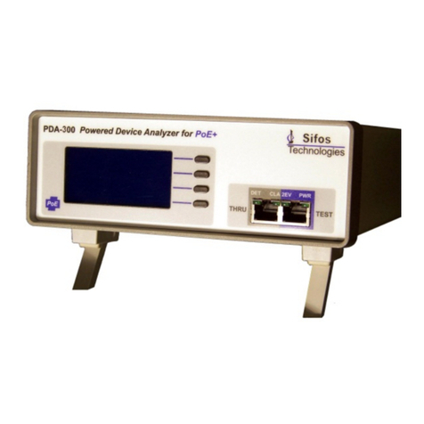
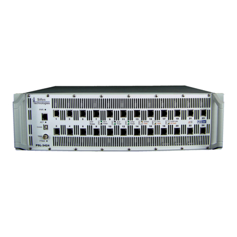
Sifos Technologies PowerSync Series User manual

PSA / PVA Installation Guide
Copyright © 2009-2019 Sifos Technologies, Inc., All Rights Reserved
Sifos Technologies
PowerSync & PhyView Analyzers
PSA-3000
PSA-3002
PSA-3248
PVA-3048
PSA-3402
PVA-3000
PVA-3002
PSL-3000
PSL-3224
PSL-3024
PDA-LLDP
Installation Guide
December 4, 2019
®
®

PSA / PVA Installation Guide
December 4, 2019 Sifos Technologies Page 2
Sifos Technologies, Inc.
(978) 640-4900 Phone
(978) 640-4990 FAX
Disclaimer
The information contained in this manual is the property of Sifos Technologies, Inc., and is furnished for use by
recipient only for the purpose stated in the Software License Agreement accompanying the user documentation.
Except as permitted by such License Agreement, no part of this publication may be reproduced, stored in a retrieval
system, or transmitted, in any form or by any means, without the prior written permission of Sifos Technologies, Inc.
Information contained in the user documentation is subject to change without notice and does not represent a
commitment on the part of Sifos Technologies, Inc. Sifos Technologies, Inc. assumes no responsibility or liability
for any errors or inaccuracies that may appear in the user documentation.
Products described within this manual have been subjected to safety and compliance testing as described in each
product’s respective datasheet and reference manual. If a product is used in a manner that is not described by the
respective product datasheet and/or product reference manual, then Sifos will not assure that the product meets all
claimed safety and compliance certifications.
Warranty
Sifos Technologies Inc., warrants to recipient that hardware (“Hardware”) and the tangible media on which it
supplies Software will be free from significant defects in materials and workmanship for a period of 12 months from
the date of delivery (the “Warrantee Period”), under normal and intended use and conditions*. Sifos also warrants
that during the Warranty Period, the Software that it supplies will operate substantially in accordance with the
specifications supplied by Sifos for such Software. Sifos does not warrant that the functions contained in the
Software will meet a specific requirement or that the operation will be uninterrupted or error free. Sifos shall have no
warranty obligations whatsoever with respect to any Software which has been modified in any manner by any third
party.
Defective Product under warranty shall be, at Sifos’ discretion, repaired or replaced or a credit issued for an amount equal
to the price paid for such Product provided that: (a) such Product is returned to Sifos Technologies after first obtaining a
return authorization number and shipping instructions, freight prepaid, to Sifos’ location in the United States; (b) Recipient
provides an explanation of the defect or Software failure claimed; and (c) the claimed defect actually exists and was not
caused by fault, neglect, accident, misuse, improper storage, improper installation, improper repair (other than by
Sifos or its agents), fire, flood, lightning, power surges, earthquake or alteration (unless such alteration performed by
Sifos or its agents). Sifos will ship repaired Products to recipient, freight prepaid, within ten (10) working days after
receipt of defective Product. Except as otherwise stated, any claim on account of defective materials or for any other
cause whatsoever will conclusively be deemed waived by recipient unless written notice thereof is given to Sifos
Technologies, Inc. within the Warrantee Period. Product will be subject to Sifos Technologies’ standard tolerances
for variations.
TO THE EXTENT PERMITTED BY APPLICABLE LAW, ALL IMPLIED WARRANTIES, INCLUDING BUT
NOT LIMITED TO IMPLIED WARRANTEES OF MERCHANTABILITY, NONINFRINGEMENT AND
FITNESS FOR A PARTICULAR PURPOSE, ARE HEREBY EXCLUDED, AND THE LIABILITY OF SIFOS, IF
ANY FOR DAMAGES RELATING TO ANY ALLEGEDLY DEFECTIVE PRODUCT SHALL BE LIMITED TO
THE ACTUAL PRICE PAID BY THE PURCHASER FOR SUCH PRODUCT. IN NO EVENT WILL SIFOS
TECHNOLOGIES BE LIABLE FOR COSTS OF PROCUREMENT OF SUBSTITUTE PRODUCTS OR
SERVICES, LOST PROFITS, OR ANY SPECIAL DIRECT, INDIRECT, CONSEQUENTIAL OR INCIDENTAL
DAMAGES, HOWEVER CAUSED AND ON ANY THEORY OF LIABILITY, ARISING IN ANY WAY OUT OF
THE SALE AND/OR LICENSE OF PRODUCTS OR SERVICES TO RECIPIENT EVEN IF ADVISED OF THE
POSSIBILITY OF SUCH DAMAGES AND NOTWITHSTANDING ANY FAILURE OF ESSENTIAL PURPOSE
OF ANY LIMITED REMEDY.
*Test setups that subject the Hardware to conditions beyond those described in the applicable datasheet Technical
Data or reference manual Technical Specifications for the Hardware may void the Warranty.

PSA / PVA Installation Guide
December 4, 2019 Sifos Technologies Page 3
Table of Contents
1. About This Guide................................................................................................................5
1.1. Purpose.........................................................................................................................................................5
1.2. Audience .......................................................................................................................................................5
1.3. Content..........................................................................................................................................................5
1.4. Conventions..................................................................................................................................................5
1.5. PSA Chassis Configurations........................................................................................................................5
1.6. Related Information ......................................................................................................................................5
1.7. Technical Support.........................................................................................................................................5
2. About PowerSync / PhyView Family of Instruments.......................................................6
2.1. Standard Features ........................................................................................................................................6
2.2. Applications & DUT Connections ................................................................................................................6
2.2.1. Power-over-Ethernet PSE Testing with PSA-3000 and PSL-3000 Instruments.....................................6
2.2.2. Connecting PSE’s to PSA-3000 and PSL-3000 Test ports....................................................................6
2.2.3. Connecting Ethernet Ports to PVA-3102 Test Ports..............................................................................7
2.2.4. Power-over-Ethernet PD LLDP Testing................................................................................................7
2.3. Physical and Environmental Specifications................................................................................................8
2.4. Certifications.................................................................................................................................................8
3. Installation and Setup Procedures ...................................................................................9
3.1. Host PC Requirements.................................................................................................................................9
3.2. Network Connection and Host Computer Considerations.........................................................................9
3.3. Package Contents.........................................................................................................................................9
3.4. Safety Precautions......................................................................................................................................10
3.5. Hardware Installation.................................................................................................................................. 11
3.5.1. PSA-3000 / PVA-3000 / PSL-3000 Test Blade Installation..................................................................11
3.5.2. Rack Mounting Considerations...........................................................................................................11
3.5.3. Powering Up PSA-3000, PVA-3000, and PSA-3402 Instruments........................................................11
3.5.4. Powering Up PSA-3002 and PVA-3002 Instruments...........................................................................11
3.5.5. IP Address Set-Up via Console Port..................................................................................................11
3.5.6. IP Address Set-Up via PowerShell Tcl or Wish..................................................................................14
3.5.7. DHCP Address Option........................................................................................................................14
3.5.8. IP Address Factory Default Restoration..............................................................................................14
3.5.9. Connecting the Ethernet Port .............................................................................................................14
3.6. Software Installation & Initial Connection.................................................................................................15
3.6.1. Installing PSA Software onto Microsoft Windows................................................................................15
3.6.2. Tcl/Tk Installation Problems................................................................................................................16
3.6.3. Notepad++ Editor for PowerShell PSA Programming .........................................................................16
3.6.4. Install PSA Software Onto a Linux Workstation ..................................................................................17
3.6.5. Connecting PSA Interactive, PVA Interactive, or PowerShell Wish to a PSA/PVA-3000 Instrument....18
3.6.6. Connecting PowerShell Tcl to a PSA/PVA-3000 Instrument...............................................................18
3.6.7. Connecting PSA Interactive or PowerShell Wish to a PSA-3248 or PSA-3048 Instrument..................18
3.6.8. Connecting PowerShell TCL to a PSA-3248 or PSA-3048 Instrument...............................................19
3.6.9. Inventory the PowerSync or PhyView Instrument ...............................................................................19
4. Updating Firmware in the PSA Instrument ....................................................................20
4.1. Updating Controller Firmware in a PSA-3xxx or PVA-3xxx......................................................................20
4.1.1. Updating Chassis Controller Firmware Over the LAN.........................................................................20
4.1.2. Recovering From a Failed Chassis Controller Firmware Update Over USB Console..........................20
4.1.3. Recovering From a Failed Chassis Controller Firmware Update Over RS-232 Console .....................21

PSA / PVA Installation Guide
December 4, 2019 Sifos Technologies Page 4
4.2. Updating Test Port Firmware in a PSA-3xxx or PVA-3xxx .......................................................................21
4.2.1. Step 1: Uploading the Firmware File to the Instrument .......................................................................22
4.2.2. Step 2: Upgrading Test Port Firmware................................................................................................23
4.3. Upgrading PSA-3000/PVA-3000 Test Port Firmware in a PSA-1200 Chassis..........................................23
4.3.1. Upgrade Procedure............................................................................................................................23
5. PSA-3000/PSL-3000 Software Version History..............................................................25
5.1. Current PSA-3000/PSL-3000 Firmware Versions......................................................................................25
6. PVA-3000 Software Version History ...............................................................................26
6.1. Current PVA-3000 Firmware Versions.......................................................................................................26

PSA / PVA Installation Guide
December 4, 2019 Sifos Technologies Page 5
1. About This Guide
1.1. Purpose
This manual describes first-time PowerSync Analyzer, PowerSync Programmable Load, and PhyView Analyzer
installation and setup. It also includes instructions for firmware upgrades to the PowerSync instrument.
1.2. Audience
This manual is designed for Engineers and Technicians who are familiar with PC’s and/or Linux Workstations and
have a working knowledge of networking equipment.
1.3. Content
About the PowerSync / PhyView Family of Instruments
This section introduces the user to the PowerSync and PhyView Analyzer family of products
Installation and Setup
This section describes the initial installation and setup of the PowerSync instrument and associated software.
Upgrading Instrument Firmware
This section describes processes for upgrading firmware to the PowerSync chassis and test blades.
1.4. Conventions
This guide uses the following typographical conventions:
Bold lettering is used to indicate menu selections and CLI (command line interface) typed commands, as well as for
general emphasis for important items.
NOTE! is used to convey extremely important information.
Italics is used to indicated command options and for notes to the user
Menu/submenu selections are indicated with “greater than” (>) symbols. For instance, File > Save refers to the Save
submenu selection under the file menu.
1.5. PSA Chassis Configurations
Model
Description
PSA-3000
A chassis that can host up to 12 PSA-3202, PVA-3102, and/or PSA-3102 test blades
PSL-3000
A chassis that can host up to 12 PSL-3202, PVA-3102, and/or PSL-3102 test blades
PSA-3248
A package of two PSA-3000 chassis’ hosting a total of 24 PSA-3202 test blades, i.e. 48 test ports
PSA-3048
A package of two PSA-3000 chassis’ hosting a total of 24 PSA-3102 test blades, i.e. 48 test ports
PSL-3224
A PSL-3000 chassis configured with 12 PSL-3202 test blades, i.e. 24 test ports
PSL-3024
A PSL-3000 chassis configured with 12 PSL-3102 test blades, i.e. 24 test ports
PSA-3402
A compact, single slot PSA with one PSA-3202 test blade
PSA-3002
A compact, single slot PSA with one PSA-3102 test blade and external power module
PVA-3002
A compact, single slot PVA with one PVA-3102 test blade and external power module
1.6. Related Information
In addition to this manual, the user should refer to the appropriate (PSA-3000, PSL-3000, PVA-3000) Technical
Reference Manual that is provided both in paper form and on the CD shipped with the test instrument.
1.7. Technical Support
To obtain technical support, please contact our technical support team using either of the following methods:
By mail: Sifos Technologies, Inc.
Attn: Technical Support
1 Technology Drive, Suite 100
Andover, MA 01810
Additionally, Datasheets, Application Notes, and Software Updates may be found at the Sifos Technologies web site:
http://www.sifos.com

PSA / PVA Installation Guide
December 4, 2019 Sifos Technologies Page 6
2. About PowerSync / PhyView Family of Instruments
2.1. Standard Features
All PowerSync and PhyView test instruments from Sifos Technologies have standard features that include:
An instrument controller (or controller blade) with embedded controller firmware, a 10/100BaseT control
port, a console port (either USB or RS-232), and an external trigger BNC jack. The instrument controller
supports a single user connection at any one time.
Two fully autonomous test ports per instrument or test blade with embedded test port firmware per port. A
maximum of 12 test blades, or 24 test ports, may be configured to a PSA-3000 or PSL-3000 chassis.
One RJ-45 socket per test port that should connect to a device-under-test (DUT).
A second RJ-45 socket per test port that may be switched to feed through LAN traffic to and from the DUT
socket.
Host computer software (“PSA software”) to operate the test instrument consisting of an interactive script
automation shell, PowerShell PSA, and several instrument-specific graphical user interface applications
including PSA Interactive and PVA Interactive.
PowerShell PSA, PSA Interactive, and PVA Interactive are supported on Microsoft Windows platforms
including Win10, Win8, Win7, Windows Vista, and Windows XP.
PowerShell PSA and PSA Interactive are supported on various Linux PC platforms including Red Hat (Fedora),
SUSE, and Debian distributions.
PSA Software is based on the Tcl/Tk scripting language. PowerShell PSA is the command level underpinning
to each graphical user interface application provided with PSA Software.
The console port is only provided for IP address configuration and updating controller blade firmware. There is no
text-based command-line-interface (CLI) available from the console port.
PowerSync and PhyView test instruments are exclusively controlled using the 10/100BaseT control port. A low level
proprietary protocol is utilized by PowerShell PSA host-based software to communicate with PowerSync &
PhyView test instruments. There is no support for a text-based CLI (e.g. telnet) on the 10/100BaseT control port.
PowerShell PSA is the only CLI interface to the test instrument.
2.2. Applications & DUT Connections
2.2.1. Power-over-Ethernet PSE Testing with PSA-3000 and PSL-3000 Instruments
The PowerSync Analyzer (PSA) and PowerSync Programmable Load (PSL) instruments are designed to test
IEEE 802.3at Power Sourcing Equipment (PSE’s). PSE’s are generally end-span switches and routers that deliver
DC Power superposed on 10/100/1000BaseT LAN connections. PowerSync Analyzer and PowerSync
Programmable Load test ports must mimic, under program control, certain attributes and states of Powered Devices
(PD’s) while also performing measurements on PoE related signals and power levels. Additionally, with the advent
of IEEE 802.3 PoE LLDP protocols, these test ports also mimic many potential layer 2 LLDP protocol behaviors of
second and third generation PD’s.
2.2.2. Connecting PSE’s to PSA-3000 and PSL-3000
Test ports
Each test blade (or equivalently, each slot on the PSA-
3x48, or PSL-3x24) has two pairs of RJ-45 sockets, one
pair for Port 1 and one pair for Port 2. The top socket is
labeled either THRU (PSx-3202) or OUT (PSx-3102)
while the lower of the socket pair is labeled PSE (see
Figure 1). Each test port within a test slot is fully
independent of the other test port with only one exception –
testing of 4-pair PSE’s including both new 802.3bt PSE’s
and proprietary 4-pair powering PSE’s.
Ordinary, 802.3at-compliant PSE ports need to be
connected to the PSE 1 and PSE 2 inputs. 4-pair powering
PSE’s may also be connected to PSE 1 and PSE 2 inputs on
PSx-3202 test blades while these PSE’s must be connected
to the PSE 2 input on PSx-3102 test blades and PSA-3002
instruments.
Figure 1. PSA/PSL-3000 Connections

PSA / PVA Installation Guide
December 4, 2019 Sifos Technologies Page 7
The THRU (or OUT) ports may be connected to an analyzer used for packet flow or LAN physical layer testing,
such as the Sifos PVA-3000. These ports are DC-decoupled from the PSE ports meaning they do not experience
PoE DC voltages. They are passively coupled and therefore add no packet latency and negligible physical layer
impairment to LAN signaling including 10Base-T, 100Base-Tx, 1000Base-T, and 2.5GBase-T.
When a test port is configured to emulate PoE LLDP with a PSE, the 10/100 data pairs of the THRU (or OUT) port
will not be coupled to the PSE port. In fact, the LLDP connection in a test port may be used to block cross-coupling
of low frequency PoE signals between PSE ports in commonly used “snake” test setups.
NOTE! Sifos generally recommends not connecting any devices to the THRU (or OUT) socket when running certain
PSE Conformance Tests that are sensitive to EMI termination methods or the presence of any electrical signaling at
the THRU (or OUT) socket.
Note that on the PSA-3402 and PSA-3002, the two test ports are side-by-side with Test Port 1 (OUT 1 and PSE 1)
on the left and Test Port 2 (OUT 2 and PSE 2) on the right.
See the Technical Reference Manual for further information concerning the internal architecture and the LED
indicator features of each PowerSync test port.
10/100/1000BaseT LAN Port Testing with the PVA-3000
The PhyView Analyzer (PVA) is designed to perform in-depth physical layer testing of IEEE 802.3
10/100/1000BaseT LAN interfaces. The instrument is highly unique in that it can assess transmitted signal qualities,
receiver performance, and interface RF characteristics while linked to any DUT, that is, any 10/100/1000BaseT port.
Measurements and testing of physical layer performance is fully automated requiring no external equipment or
fixtures.
PVA test blades can share a PSA-3000 or PSL-3000 chassis with
any of the PoE test blades described above. In fact, PVA test
blades can be used in tandem with PoE (PSA) test blades to
assess physical layer performance characteristics on powered
PSE ports!
2.2.3. Connecting Ethernet Ports to PVA-3102 Test Ports
Each test blade has one pair of RJ-45 sockets per test port. Test
port 1and test port 2are clearly labeled on the faceplate (see
Figure 2). The upper socket on each test port is labeled THRU
and the lower socket is labeled TEST.
Device-Under-Test (DUT) ports need to be connected to the
TEST sockets. The THRU sockets can be passively coupled to
the TEST sockets depending upon the test port configuration.
When connected accordingly, 10/100/1000BaseT LAN traffic
will flow between the TEST socket and the THRU socket. This
is a passive connection with DC-decoupling.
Normally, when performing physical layer testing, the TEST
socket is not coupled to the THRU socket. Instead, all four wire
pairs are electrically switched to an internal diagnostic transceiver that gets linked to the DUT. However, certain
types of DUT receiver testing might be done by routing external packet generators/analyzers through the PhyView
Analyzer test port in order to utilize programmable passive channel impairments that available in the test port. In this
case, the external packet analyzer would be connected to the THRU socket.
Note that on the PVA-3002, the two test ports are side-by-side with test port 1on the left and test port 2on the right.
See the Technical Reference Manual for further information concerning the internal architecture and the LED
indicator features of each PhyView Analyzer test port.
2.2.4. Power-over-Ethernet PD LLDP Testing
The PDA-LLDP is designed solely for assessing PoE LLDP protocols while testing an IEEE 802.3at compliant
Powered Device (PD). Typical configurations and hook-ups for performing this type of testing is provided in the
PDA-LLDP Technical Reference Manual.
Figure 2. PVA-3000 Connections

PSA / PVA Installation Guide
December 4, 2019 Sifos Technologies Page 8
2.3. Physical and Environmental Specifications
PHYSICAL
PSA-3002, PVA-3002, PDA-LLDP
Width: 4.2”
Height: 1.65”
Depth: 9.15” (Including Rear-Panel Connectors)
Weight: 1.4 lbs.
Power: 5V, 1.2A Max. (100VAC –240VAC, 50-60Hz Wall Plug-in Adaptor Supplied)
PSA-3000, PSL-3000, PSA-3x48, PSL-3x24
Width: 19”
Height: 5.25” (3 Rack-Unit)
Depth: 12”
Weight: 20.4 lbs. (Fully Populated)
Power: 100VAC-240VAC, 50-60Hz, 2A Max.
Mains supply voltage fluctuations are not to exceed +/- 10% of the nominal
supply voltage
PSA-3402
Width: 7.5”
Height: 3.0”
Depth: 10.0”
Weight: 3.2 lbs.
Power: 100VAC –240VAC, 50-60 Hz, 0.25A Max.
ENVIRONMENTAL
Operating Temperature: 5°C to 40°C
Storage Temperature: -20°C to 85°C
Operating Humidity: 5% to 95% RH, Non-Condensing
Altitude: 2000 Meters
Pollution Degree: 2
2.4. Certifications
Emissions: FCC Part 15, Class A
Meets EN55011, VCCI, AS/NZS 3548, ICES-001
Safety: CSA Listed (CSA22.2 No. 61010)
Meets EN61010-1 (All except PSA-3402)
Meets EN61010-12 (PSA-3402)
European Commission: Low Voltage Directive (2014/35/EU)
Electromagnetic Compatibility Directive (2014/30/EU)
CE Marking Directive (93/68/EEC)
FCC Statement:
This equipment has been tested and found to comply with the limits for a Class A digital device, pursuant
to part 15 of the FCC Rules. These limits are designed to provide reasonable protection against harmful
interference when the equipment is operated in a commercial environment. This equipment generates,
uses, and can radiate radio frequency energy and, if not installed and used in accordance with the
instructions, may cause harmful interference to radio communications. Operation of this equipment in a
residential area is likely to cause harmful interference in which case the user will be required to correct the
interference at his own expense.

PSA / PVA Installation Guide
December 4, 2019 Sifos Technologies Page 9
3. Installation and Setup Procedures
3.1. Host PC Requirements
IBM Compatible PC running Microsoft Windows 10™, Windows 8™, Windows 7™, Windows Vista™, or
Windows XP™.
Microsoft Excel 2016, 2013, 2010, or 2007 is required for standard report generation associated with the PSE
Conformance Test Suite, the PSE Multi-Port Test Suite, the PVA PHY Performance Test Suite, PSA/PVA-3000
Graphic Reports, and PSA-3000/PSL-3000 LLDP Protocol Reporting.
NOTE! Microsoft Excel must be configured to allow macros to run automatically or alternatively, to allow
macros to run from Sifos Reporting directories such as \Users\Public\Sifos\PSA3000\Results\ or \Program
Files\Sifos\PSA3000\Results\. Note that Excel may produce vague or misleading error messages such as “low
memory” when macros are not enabled! Use the [File] [Options] [Trust Center] menu to enable macros.
NOTE! If installing Microsoft Office, perform that installation BEFORE installing PSA Software.
PSA software is also available for SUSE, RedHat (Fedora), and Debian Linux Workstations.
400MHz Pentium or higher recommended. Minimum 60MB Drive space and 512MB RAM required for PSA
Software.
SVGA Color Monitor, Mouse, CD Rom Drive, and depending upon PSA-3000 Console Port, either USB 2.0
interface or an RS232 serial port that supports hardware flow control.
10/100Base-T or 10/100/1000Base-T LAN interface –if direct connected to a PowerSync or PhyView
instrument, a crossover cable will be required if the PC LAN interface is not auto-MDI capable.
Tcl/Tk Version 8.4.5 –8.4.nn. (Tcl versions 8.5 and later are not officially supported by Sifos.) Tcl/Tk 8.4.20 is
provided as part of the Microsoft Windows installer application for PSA Software. Customers with Linux
workstation hosts must independently install Tcl/Tk prior to using PSA Software.
3.2. Network Connection and Host Computer Considerations
As is typical of most LAN controlled instruments, the PowerSync and PhyView instruments generally utilize fixed
IP Addresses and therefore should only be used on a private LAN network. PC’s and workstations that will control
these instruments should have capability to reside on this private LAN using either a fixed IP Address or a carefully
administered address provisioning method that protects against address conflicts with instruments utilizing fixed IP
addresses.
PC’s and workstations may host a second network connection via a separate LAN interface to a building or enterprise
network. In the event that a second LAN interface is utilized for wide area networking purposes, it is recommended
that the two LAN interfaces be kept completely separate with no route paths between them. See applicable PC and
operating system literature when configuring multiple LAN interfaces.
The network connection between host computer and instrument should not introduce significant delay or
latency. Network connection latencies exceeding 15 msec can adversely impact automated tests and utilities
affiliated with the PSA instrument. The host computer should be able to run PSA Software, particularly any
automated tests and utilities, without severe run-time process preemption. See Network Latency, Host Software,
and Host Firewall Considerations (Section 2.5) in the applicable (PSA-3000, PSL-3000, PVA-3000) Technical
Reference Manual to assure that host PC and network configurations will properly support automated tests and
utilities available for the PSA instrument.
3.3. Package Contents
The PSA-3402, PSA-3002, PVA-3002, and PDA-LLDP Compact Analyzers are shipped with the following items:
Dual test port “compact” instrument
PSA/PVA/PSL Software Installation CD
AC wall-mount power supply (not applicable to PSA-3402)
CAT5e Ethernet cables, crossover and standard
RS232 Straight-through cable with DB9M to DB9F connections.
Installation and Technical Reference Manuals (paper and on CD)
Two High-Quality, 5 ft. color-coded Test Leads (PVA-3002 only)

PSA / PVA Installation Guide
December 4, 2019 Sifos Technologies Page 10
The PSA-3000, PVA-3000, PSL-3000, PSL-3224, PSL-3024 Analyzers and Programmable Loads are shipped with
the following items:
PSA-3000/PSL-3000 chassis with one PSA-3000 controller blade, one or more test blades, and blank faceplates
to cover any unused slots (Note: PSL-3024 uses a single faceplate for all test ports)
One or more test blades up to 12 maximum (PSA-3x02, PVA-3102, or PSL-3x02)
PSA/PVA/PSL Software Installation CD
AC power cord
CAT5e Ethernet cables, crossover and standard
Console cable (Either USB A-B or RS232 Straight-through cable with DB9M to DB9F connections.)
Installation and Technical Reference Manuals (hard copy and on CD)
Two High-Quality, 5 ft. color-coded Test Leads per PVA-3102 test blade (PVA-3000 only)
The PSA-3248, PSA-3048 RackPack PowerSync Analyzer is shipped with the following items:
(2) PSA-3000 chassis’ with 24 PowerSync Analyzer test ports per chassis, each chassis with single faceplate
covering all 24 test ports
PSA/PVA/PSL Software Installation CD
(2) AC power cords
(2) CAT5e Ethernet cables, straight-through
Console cable (Either USB A-B or RS232 Straight-through cable with DB9M to DB9F connections.)
Installation and Technical Reference Manuals (hard copy and on CD)
3.4. Safety Precautions
TO PREVENT ELECTRIC SHOCK, DO NOT REMOVE THE COVER OF THE PSA. NO USER SERVICEABLE
PARTS ARE INSIDE. SERVICE SHOULD BE REFERRED TO QUALIFIED PERSONNEL.
THE PSA SHOULD BE POWERED DOWN AND DISCONNECTED FROM AC LINE VOLTAGES WHEN ANY
OF THE CARD SLOTS ARE UNPOPULATED OR UNCOVERED BY A BLANK FACEPLATE, AND WHEN
INSTALLING OR REMOVING CARDS OR FACEPLATES.
THE REMOVEABLE TEST CARDS MAY EXCEED SAFE HANDLING TEMPERATURES WHEN
OPERATING UNDER HEAVY CURRENT LOADS. CARDS SHOULD ALWAYS BE ALLOWED TO COOL
BEFORE REMOVAL FROM THE CHASSIS.
THE PSA IS FOR CONNECTION ONLY TO THE INTERNAL BUILDING ETHERNET NETWORK. IT IS NOT
FOR CONNECTION TO THE TELECOMMUNICATIONS NETWORK. THE PSA IS FOR INDOOR USE
ONLY.
THE PSA SHOULD BE POWERED VIA THE SUPPLIED AC POWER CORD, WHICH INCLUDES AN
EARTHING CONDUCTOR. THE GROUND TERMINAL OF THE PLUG SHOULD NOT BE MODIFIED,
SINCE THIS COULD RESULT IN A PRODUCT THAT IS NOT PROPERLY EARTHED. WHEN PLACING
THE EQUIPMENT IN ITS FINAL CONFIGURATION, THE EQUIPMENT SHOULD BE PLACED SUCH THAT
IT IS EASY TO ACCESS THE POWER CORD; THIS WILL ALLOW THE CORD TO BE PULLED OUT OF
THE UNIT IN THE EVENT THAT IT IS NECESSARY TO REMOVE POWER.
THERE ARE VENTILATION HOLES ON THE TOP AND BOTTOM COVERS, AND FAN VENT HOLES ON
THE BACK OF THE PSA-3000, PSA-3248, PSA-3048, PSL-3000, PSL-3224 AND PSL-3024 CHASSIS’. THERE
ARE VENTILATION HOLES ON THE SIDE AND FAN VENT HOLES IN THE BACK OF THE PSA-3402.
THERE ARE VENTILATION HOLES ON THE SIDE AND FAN VENT HOLES IN THE TOP OF THE PSA-
3002. THESE OPENINGS SHOULD NEVER BE BLOCKED OR OTHERWISE OBSTRUCTED DURING
INSTRUMENT OPERATION.
WARNING! THE PSA-3002 and PVA-3002 SHOULD ONLY BE OPERATED WITH THE POWER
SUPPLY THAT WAS PROVIDED WITH THAT PRODUCT.

PSA / PVA Installation Guide
December 4, 2019 Sifos Technologies Page 11
3.5. Hardware Installation
3.5.1. PSA-3000 / PVA-3000 / PSL-3000 Test Blade Installation
The chassis slots for the PSA-3x02, PVA-3102, and PSL-3x02 blades are numbered from 1-12 (left to right) in the
frame. Blades should generally be installed from left to right, however this is not a strict requirement for proper
operation of the instrument under software control. In PSA software, test ports are addressed generally by Slot
number and Port number.
Note: Test blade installation is not applicable to the PSA-3402, PSA-3002, PVA-3002, PSL-3x24, and PSA-3x48.
These models are fully populated with test blades as furnished.
3.5.2. Rack Mounting Considerations
Chassis-based configurations may be operated stand-alone or mounted inside a 19-inch rack.
The top and bottom air vents and back-panel fans on the chassis provide required cooling for the test cards. Cooling
is especially important for PowerSync test blades as those have the capability to generate up to 100 watts of heat per
test blade. When rack mounting the chassis, a 1U (1.7”) spacing must be maintained above and below the
instrument, without front-side obstructions.
NOTE! OBSTRUCTION OF THE TOP OR BOTTOM VENTS OR THE FANS COULD DAMAGE THE
HARDWARE UNDER HEAVY CURRENT PoE LOADS, AND WILL VOID THE WARRANTY.
3.5.3. Powering Up PSA-3000, PVA-3000, and PSA-3402 Instruments
Connect the supplied AC cord to the back of the chassis, and then to a properly grounded AC outlet (see “Safety
Precautions”). Turn on the power switch on the back of the chassis. The test ports should all flash their LED’s for
about 2 seconds, and the PSA controller should then flash its LED indicators briefly. At this point, the instrument is
available for all testing operations.
NOTE! The ground connection between the instrument and the AC outlet should never be removed or bypassed.
3.5.4. Powering Up PSA-3002 and PVA-3002 Instruments
Connect the supplied modular power supply to the 5VDC input in the rear of the instrument and then to a properly
grounded AC outlet (see “Safety Precautions”). If provided, press the momentary power switch in the back of the
chassis. The test ports should all flash their LED’s for about 2 seconds, and the PSA controller should then flash its
LED indicators briefly. At this point, the instrument is available for all testing operations.
NOTE! Use of a modular power supply other than the AC adapter furnished by Sifos is not recommended and may
have adverse consequences to either the test instrument and/or to measurement and testing results. Under no
circumstances should the GROUND connection on the modular power supply be removed or bypassed.
3.5.5. IP Address Set-Up via Console Port
The instrument is typically shipped from the factory with an IP Address of 192.168.221.105. (PSA-3x48’s are
configured with addresses 192.168.221.105 and 192.168.221.106.) Under typical situations, the user will probably
need to change this to an address that matches their local network settings.
Users may work with the Console port to re-configure IP address and IP mask bits. Newer Console ports are USB
while older Console ports are RS-232 DB9 connections on the PSA/PSL-3000 slot 0 controller blade. In either case,
the communication protocol is RS-232 and the Console port is treated as a Serial (“COM”) port in the host PC.
Terminal emulation software (e.g. HyperTerminal) may then be used to communicate from the host computer.
NOTE! The PowerSync instrument’s console port is available exclusively for IP Address set-up and PSA Controller
firmware updates. Under normal use it should be left disconnected. IP address configuration and PSA Controller
firmware may also be performed from PowerShell PSA software without using the Console Port.
USB Console Connections –PSA-3000 and PSA-3402
If the PSA-3000 controller includes a USB (type B) jack, then a USB connection should be made to the host
computer. Generally, both the host computer and the PSA/PSL instrument should be turned on before completing
the USB connection. Communication over USB to the Console port will require that host PC have driver software
required to recognize the FTDI RS-232 Serial to USB converter and then map that interface to a virtual COM port.
The required driver software depends on the instrument:
PSA/PSL/PVA-3000 Chassis: ftdibus.inf and associated files for 32-bit and 64-bit computers
PSA-3402: psa3000port.inf and associated files for 32-bit and 64-bit computers

PSA / PVA Installation Guide
December 4, 2019 Sifos Technologies Page 12
Figure 4. Downloading Driver from Internet
Figure 5. Installing FTDI Driver from CD
When working with Microsoft Windows, there are four scenarios for activating the USB Console port connection:
1. The host Windows PC already has the required FTDI USB driver installed and recognizes the connection.
2. The host Windows PC already has the required FTDI USB driver available and will install it.
3. The host Windows PC does not have the driver, but will automatically search the internet to obtain and install
the appropriate FTDI USB driver. Note that the PSA-3402 USB driver is not available from the internet.
4. The host Windows PD does not have the driver and is not connected to the Internet, so the USB driver will need
to be installed locally, either from a location on the host PC or
from the Sifos Installation CD.
If the host PC already has the required FTDI driver installed and
recognizes the connection, then communication over the USB
connection can be
initiated using a
terminal emulator
program (e.g.
Hyperterminal).
If the host PC
already has the
required FTDI driver available but not installed, a message will
appear indicating that device driver software is being installed.
Clicking status will then produce the confirmation when the driver
completes installing (see Figure 3).
If the host PC does not have the FTDI driver, but it is connected to
the Internet, it can automatically search the internet to obtain and
install the appropriate FTDI driver and install it (see Figure 4).
Clicking status will show this process and indicate when
completed. (Note: The PSA-3402 driver will not be available.)
If the host PC does not have the FTDI driver and/or is not
connected to the Internet, the driver may be loaded from the either
a Sifos directory location or from the PSA Software CD furnished with the PSA instrument. PSA Installers starting
with version 4.2.7 and 5.0.00 will place the USB drivers as follows:
Windows Vista,7,8,10:
\Users\Public\Sifos\PSA**00\Config\USB Serial Console\
Windows Xp:
\Program Files\Sifos\PSA**00\Config\USB Serial Console\
Alternatively, the drivers may be found on the PSA Software CD
(versions 4.2.7 and later) under the
USB Serial Console\ directory.
To install the appropriate driver, open the Windows Computer
management menu to access the Device Manager (see Figure
5). Open Device Manager and scan Other Devices for a USB
Serial Port. Select the USB Serial Port and then select the
Update Driver Software… option that appears as shown in
Figure 5. When the Search menu opens, select the Browse my
computer for driver software option.
Locate the USB Serial Console directory to
be used, then navigate to the proper driver
directory as follows:
Press OK. When Windows finds the proper driver software, press Next and Windows will install the FDTI driver.
Model
WinOS
Subdirectory
PSA, PSL,
PVA-3000
Any
\PSA-3000
Drivers
PSA-3402
Win
Vista,7,
8,10
\PSA-3402
Drivers\Win
Vista,7,8,10
Win Xp
\PSA-3402
Drivers\Win XP
Figure 3. Automatic FTDI Driver Installation

PSA / PVA Installation Guide
December 4, 2019 Sifos Technologies Page 13
The PSA/PSL/PVA-3000 USB driver is also available from the web at:
http://www.ftdichip.com/
Drivers/VCP.htm
Drivers for a Linux PC are also available from this same location.
Once the driver is installed and running, Windows will automatically assign a
“virtual” COM port number to the USB interface. This is readily discovered
using the Device Manager under Ports (COM and LPT). In Figure 6,
Windows has assigned COM6 to the USB connection.
NOTE! Application notes from FTDI covering USB driver installation on
various Microsoft Windows versions are included on the software CD under
\USB Serial Console\..
RS-232 Console Connections
Connect a standard RS-232 cable with DB9 connectors (furnished with the instrument) from host PC to the PSA
controller (front of PSA-3000, rear of PSA/PVA-3002).
Then configure the terminal emulator as described below.
Configuring Terminal Emulator and Setting IP Address
The HyperTerminal terminal emulator is set-up is as follows:
Start HyperTerminal,
Select a connection name when prompted
In the connection dialog, enter the COM x port for Connect using
(see Figure7). This is the RS-232 serial or virtual COM port in the host PC.
In the Port Settings dialog, select the following parameters:
Bits per second > 9600
Data bits > 8
Parity > None
Stop bits > 1
Flow Control > Hardware
With HyperTerminal set up and running as described above, hit the ENTER
key on the Keyboard. The following menu will appear:
Type 1and press ENTER. Follow the command prompts to set up the IP address. Note that the IP mask is entered
as a bit count of 1’s where, for
example, 255.255.255.0 is 24 ‘1’
bits..
There is approximately a 10-second
delay before “Done” is displayed,
and then the main menu appears
again.
Type “3” to Enable the PSA. Then
disconnect the serial port and close
the terminal emulation software.
>1
Use DHCP ? (Y/N)> N
Enter IP Address (xxx.xxx.xxx.xxx) > 10.10.10.114
Confirm? (Y/N) y
Enter Number of Mask Bits (01 –30) > 24
255.255.255.0
Confirm? (Y/N) y
Enter Gateway Address (xxx.xxx.xxx.xxx) >
10.10.10.1
Confirm? (Y/N) y
Figure 6. COM Port Assignment
PowerSync Analyzer
Firmware Version #.##
MAC Address: 00204A######
IP Address: 192.168.221.105
Mask: 255.255.255.0
Gateway: 192.168.1.1
1. Set IP Address
2. Firmware Upgrade (Controller)
3. Enable PSA
(PSA DISABLED) >
Figure 7. Console Connection

PSA / PVA Installation Guide
December 4, 2019 Sifos Technologies Page 14
NOTE! The PSA LAN interface will not operate if the serial port to the PSA is open and the command menu is
visible as a result of pressing the ENTER key.
3.5.6. IP Address Set-Up via PowerShell Tcl or Wish
To alter the default IP address to another fixed address, users may use PowerShell Wish or PowerShell Tcl to
connect to 192.168.221.105, then use the psa_setipaddress command (see PSA-3000, PSL-3000, or PVA-3000
Technical Reference Manual section 4.10) in PowerShell Wish or Tcl to alter the address and IP mask to another
setup. This method of configuring IP address avoids the need to interface to the Console port, however, care must be
taken to change the address and mask to one that is compatible with the host PC’s subnet. For example, if the subnet
mask is 255.255.255.0, then the new IP address must remain in the 192.168.221.*** subnet. This will enable re-
connection to the new IP address after the change is made.
If setting up more than one instrument, as in the case of the PSA-3x48 RackPack, each PSA chassis must have a
unique IP Address that is on a common subnet. The default PSA-3x48 RackPack addresses are 192.168.221.105
and 192.168.221.106.
NOTE! Once you have changed the IP Address in PowerShell, you will need to use the PowerShell psa command to
re-connect to the instrument at its new IP address.
3.5.7. DHCP Address Option
When configuring an IP address, if DHCP is selected, the PSA will attempt to acquire an address from a network
DHCP server. Generally, this configuration is not advised for test laboratory environments where most instruments
operate with hard-coded addresses. Knowledge of the PSA address is critical in order to connect and control the
PSA from PSA Interactive or PowerShell, so if DHCP is utilized, the assigned address must be known and must be
stable over the course of instrument usage. (Note: The PSA console menu will display the acquired address if the
DHCP request is successful.)
If the Controller is unable to obtain an address, a message such as “No response to DHCP request” will be displayed.
At this point, you have the option of trying DHCP again, or configuring a static IP address. NOTE! The PSA must
have a valid IP address in order to be accessed by PowerShell.
3.5.8. IP Address Factory Default Restoration
PSA-3000, PSL-3000 Chassis Based Instruments and PSA-3402 Compact PSA
Chassis-based instruments with USB console interfaces on the controller blade also include a recessed pushbutton, IP
Reset, that can be used to restore the factory default IP address of 192.168.221.105. To restore the factory default IP
address, press the recessed button for up to 30 seconds until the LAN LED blinks rapidly, then wait until the LAN
LED transitions to a steadily “OFF” state. (PSA-3402: Look for one or two blinks on the LAN control port LED’s.)
A similar ability exists for chassis-based instruments with RS-232 console interfaces if they are running PSA
controller firmware 3.0c or later. However, this requires a special intervention with the serial connector on the PSA
Controller Blade. The user is advised to contact Sifos support for further information and instructions related to
chassis instrument factory IP address restoration.
PSA-3002, PVA-3002 Compact Instruments
PSA-3002 and PVA-3002 instruments equipped with an On/Off power switch on the rear panel can reset IP address
to the factory default address 192.168.221.105 as follows: Turn power on to the instrument, then depress the On/Off
switch continuously for a period of 20 seconds or more. This will result in a flashing of the LED power indicator that
indicates the restoration of the original factory set address. PowerShell PSA can then be utilized to connect to the
instrument at the factory default address and then to modify that address using the psa_setipaddress command in
PowerShell PSA.
3.5.9. Connecting the Ethernet Port
The Ethernet Port on the instrument can be connected to any 10/100/1000BaseT Ethernet Switch or Hub.
Connections to a Hub or Switch will require a standard CAT5 (or better) UTP patch cable.
The Ethernet Port on the instrument can also be connected directly to a host PC. When connecting an instrument that
has the factory default IP address directly to a PC, the PC TCP/IP networking properties must initially include a
192.168.221.xxx fixed IP address with subnet mask bits 255.255.255.0. Direct Connections to a PC may require the
CAT5e Ethernet crossover cable if the PC LAN interface does not support auto-MDI.
If the instrument is to be used in a networking environment with multiple subnets, the host PC must be able to access
the subnet that the instrument is on, in order to communicate with it. If the instrument is located on a different subnet
from the PC, the routing table in the PC must describe how to route to that subnet (and a gateway must exist between
the subnets).

PSA / PVA Installation Guide
December 4, 2019 Sifos Technologies Page 15
NOTE! The PSA-3x48 RackPack PSA requires that both (at least 2) PSA chassis’ be installed on the same sub-net
and remain powered on, in order for the PowerShell PSA and PSA Interactive to operate them.
Test Port LED Indicators
Each test port generally includes 4 LED indicators. The purpose and function of each of these indicators is described
in Technical Specifications at the end of Section 2 of the Technical Reference Manual.
Controller LED Indicators
The instrument controller has two LED’s on the RJ-45 Ethernet connector, and, in the case of the chassis-based
configurations (e.g. PSA-3000), two additional front panel LED’s labeled PWR and ETH. (Note that older PSA-
3000/PSL-3000s also include an LED labeled COM.)
RJ-45 Ethernet Upper/Right LED - The upper LED is a bi-color LED, which indicates whether the Ethernet
connection is 10BaseT or 100BaseTx. An Amber color indicates 10BaseT, and Green indicates 100BaseTx. If the
LED is not lit, then a proper connection is not present.
RJ-45 Ethernet Lower/Left LED - The lower LED indicates that there is activity on the link. Half-duplex activity is
indicated with a momentary Amber color, and Full-Duplex activity is indicated with green.
ETH LED - The ETH LED is lit whenever there is a communication with the controller. This can represent either; a
direct communication between the host PC and controller, or communications between the controller and a test port.
COM LED - The COM LED is lit momentarily during RS232 communications. This LED is not present on PSA-
3000/PSL-3000 controllers with a USB console interface.
Both of the above LED’s are lit momentarily during power-up, and flash during upload procedures.
PWR LED - The PWR LED is lit whenever the instrument is powered on.
3.6. Software Installation & Initial Connection
3.6.1. Installing PSA Software onto Microsoft Windows
Put the PSA, PVA, PSL Installation CD in the drive and wait for the installation
wizard to open up. The PSA software installer, PSA_Installer_#.#.#.exe, should
automatically run as shown in Figure 8.
1. Click Install. If Tcl/Tk 8.6 is not installed, a Tcl/Tk 8.6 dialog box will
appear so that Tcl 8.6.9 can be installed (see Figure 9). Tcl/Tk must be
installed in order for PSA software to operate.
Note! PSA software installers prior to version
5.1.00 may have installed Tcl 8.4.6 or Tcl 8.4.20.
However, if Tcl 8.6 is not present, the default
behavior of the installer will be to place Tcl 8.6.9
on host in a Sifos-specific location. This newer
feature will help to insulate PSA software from
other Tcl installations performed by non-Sifos
applications.
2. If Tcl/Tk 8.6 software is installed, it will be placed
in either c:\Program Files (x86)\Sifos\tcl8.6.9\ or
c:\Program Files\Sifos\tcl8.6.9\ depending upon
Windows OS version. If Tcl/Tk 8.6 is already
installed, this dialog will not appear.
3. A dialog then opens to allow entry of Product Keys
for the 2-Pair (802.3at) PSE Conformance Test
Suite and also for the 4-Pair (802.3bt) PSE
Conformance Test Suite (see Figure 10). NOTE! This dialog is not relevant when installing software to
operate PVA-3000 and PSL-3000 instruments and may simply be bypassed by pressing the SKIP button.
This dialog allows customers who have PSA-3000 instruments licensed for the PSE Conformance Test Suite
to update to the current version of that test suite provided that they are active with PSE Conformance Test
Tracking Service. The dialog accepts product keys for the presently supported 2-Pair (e.g. 802.3at) PSE
Conformance Test Suite and also for a 4-Pair PSE Conformance Test Suite for 802.3bt 4-Pair PSE’s.
Figure 8. PSA Software Installation
Figure 9. Tcl/Tk Installation

PSA / PVA Installation Guide
December 4, 2019 Sifos Technologies Page 16
Important! Product keys are available from the
Sifos website to all customers who are active on PSE
Conformance Test Tracking Service.
Product keys are specific to each new release of PSA
Software and also to each test suite (2-Pair and 4-
Pair). When installing a new PSA software release,
the appropriate product key must first be obtained
from the Sifos website.
To install using a product key, the product key(s) is
entered into the appropriate box and the USE KEY
button is pressed. Provided that the product key is
correct for the present version of PSA software, PSA
software will be installed with the PSE Conformance
Test Suite activated. If an incorrect product key is
entered, the software installation will be aborted and
PSA software will not be updated. If the SKIP
button is pressed, the new version of PSA software will be installed, however, the PSE Conformance Test Suite
will not be enabled and will not run regardless of PSA-3000 instrument licenses.
NOTE! Customers who have the PSE Conformance Test Suite but are no longer active with Tracking Service
agreements should carefully consider whether to update to the new PSA software version without first
reactivating Tracking Service for PSE Conformance Test.
4. Once the USE KEY or SKIP button is pressed, the license
agreement dialog will open (see Figure 11). Once the
Install button is pressed, PSA Software will be installed.
If an older version of PSA software already exists on the
host computer, the current version will still be installed to
replace that older version. Generally, all program files
associated with PSA Software are placed in either
c:\Program Files (x86)\Sifos\PSA3000\or c:\Program
Files\Sifos\PSA3000\while data files and user-modifiable
files are placed in accordance with Section 2.4 of the
instrument’s Technical Reference Manual.
5. Upon completion, the notification of Figure 12 will appear
when the software is successfully installed.
3.6.2. Tcl/Tk Installation Problems
Prior to the PSA 5.1.00 release, occasional problems developed
with installing Tcl/Tk on systems where a non-Sifos version of
Tcl was already installed. Often, these versions are not complete
Tcl/Tk installations and would not therefore support PSA
software. As an example, certain CAD software applications are
known to install a special version of Tcl.
With the PSA 5.1 and newer installers, Tcl/Tk 8.6 is installed in a
manner that will allow it to co-exist with non-Sifos installed Tcl
packets. If there are any issues with Tcl/Tk 8.6 installation, it is
recommended that Sifos Support be contacted.
3.6.3. Notepad++ Editor for PowerShell PSA Programming
PowerShell PSA automated testing scripts may be created and
edited in the freely available Notepad++ source code editor that
is readily available on the web (e.g. https://notepad-plus-
plus.org). This powerful editor is knowledgeable of Tcl/Tk and
PowerShell PSA commands, global variables, and other common
syntactical constructs such as braces and brackets, math
operators, etc (see Figure 13). It provides many powerful
capabilities that support authoring and troubleshooting bug-free
scripts.
Figure 10. PSE Conformance Test Suite Activation
Figure 11. PSA Software Installation
Figure 12
. Installation Complete

PSA / PVA Installation Guide
December 4, 2019 Sifos Technologies Page 17
To configure Notepad++ for
PowerShell PSA, first install
Notepad++, then use the
Language drop-down menu to
Define Your Language…, then
select the Import control and
import the file
PowerShell_PSA.xml from the
installed directory for PSA
software. This will typically be
either c:\Program Files
(x86)\Sifos\PSA3000\or
c:\Program
Files\Sifos\PSA3000\
depending upon Microsoft
Windows OS version.
3.6.4. Install PSA Software Onto a Linux Workstation
PSA Software requires Tcl/Tk 8.4.5 (or later) to operate.
NOTE! As of the PSA 5.1 and later releases, Tcl 8.5 and Tcl 8.6 are supported and Tcl/Tk 8.6.9 is recommended.
Tcl/Tk should be installed on the Linux Workstation separate from PSA Software. Tcl/Tk for Linux and Unix is
available from the ActiveState website, and usually available through Linux distribution specific package managers.
Tcl/Tk must be installed such that the user has Execute permissions to the Tcl “/bin” directory so that the commands
“tclsh8.6” and “wish8.6” will open their respective Tcl consoles.
In addition to Tcl/Tk, PSA software also requires the bwidget (version 1.7 or later) library for Tcl/Tk. This package
should be installed under the …/tcl8.*/lib/ directory.
Once, Tcl/Tk and the bwidget library are installed to the host computer, install PSA software as follows:
1. Put the PowerSync CD in the drive.
2. Establish read-write permissions for the /usr/local/ directory path
3. Copy the files psa_installer.sh and Sifos_PSA_Archive_5_#_##.tar (where #_#_## is the PSA version
number) from the directory /Linux Installation Files to the user’s <HOME>/bin/ directory path.
4. If running the PSE Conformance Test Suite, a second .tar archive Sifos_PSA_2P_CTS_5#_#_##.tar must be
obtained from the Sifos website (Product Download pages) accessible only to customers active on PSE
Conformance Test Tracking Service. This file should also be placed in the user’s <HOME>/bin/ directory path.
5. Open a terminal and execute the shell command “sh psa_installer_5.sh”.
6. Read-write permissions to the /usr/local/ directory path may be removed following execution of the installer
script.
7. Desktop icons, or application links, may be set up to PowerShell TCL, PowerShell WISH, PSA Interactive,
and PVA Interactive.The corresponding shell scripts for each of these applications will be found in the
<HOME>/bin/ directory path after execution of the installer script.
Refer to the PSA_Linux-Unix_Install_README document on the CD under the path /Linux Installation Files for
more information regarding the Linux installation process.
Terminal commands to launch PowerSync Software will be:
PSA/PVA Program
Linux Shell Command
PowerShell Tcl
PowerShell_TCL.sh
PowerShell Wish
PowerShell_WISH.sh
PSA Interactive
PSA_Interactive.sh
PVA Interactive
PVA_Interactive.sh
Figure 13. PowerShell PSA Scripting in Notepad ++

PSA / PVA Installation Guide
December 4, 2019 Sifos Technologies Page 18
3.6.5. Connecting PSA Interactive, PVA Interactive, or PowerShell Wish to a PSA/PVA-3000 Instrument
PSA Software must initially learn the IP address of each PowerSync and/or PhyView instrument on the local
network. The assumed address of a PowerSync Analyzer or PowerSync Programmable Load after the software is
installed is the factory default address 192.168.221.105.
If this is not the address configured in the instrument and if PowerShell Tcl
has not yet been used to connect to the PSA, the following procedure will
“train” all PSA Software as to where the PSA is located on the LAN.
1. Connect the instrument to the local network and turn it on.
2. Open PSA Interactive,PVA Interactive, or PowerShell Wish.
3. Enter the new PSA address in the Chassis Selection dialog entry field.
Then press Add Chassis (see figure 14).
4. Assuming the new address is discovered and added to the selection list,
Select the new address from the list, then press Connect.
If the new address was not discovered, be sure PSA is connected on LAN and
subnet visible to host computer and that instrument is turned on. Also be sure
the IP address of the instrument was properly entered before pressing the Add
Chassis button.
PSA Software is now able to communicate with the instrument. If for any reason the IP address is modified later,
then this same sequence of steps should be performed.
3.6.6. Connecting PowerShell Tcl to a PSA/PVA-3000
Instrument
PSA Software must initially learn the IP address of each
PowerSync and/or PhyView instrument on the local
network. The assumed address of a PowerSync Analyzer
or PowerSync Programmable Load after the software is
installed is 192.168.221.105.
If this is not the address configured in the PSA and if
PowerShell Tcl has not yet been used to connect to the
PSA, the following procedure will “train” PSA Software as
to where the PSA is located on the LAN.
1. Connect the instrument to the local network and turn
it on.
2. Open PowerShell Tcl and respond “N” or “NO” at the initial user connection prompt (see figure 15).
3. Enter the new PSA chassis IP address at the prompt and press [Enter].
If the new address was not accepted, be sure instrument is connected on LAN and subnet visible to host computer and
that instrument is turned on. Also be sure the IP address of the instrument was properly entered before opening
PowerShell.
NOTE! If PSA software fails to find a valid instrument IP address, it may open in Demo Mode. See PSA-3000 or
PSL-3000 Technical Reference Manual section 3.13 or 4.2 or see PVA-3000 Technical Reference Manual 3.2 or
4.2 to clear Demo Mode and connect to a new instrument address.
PSA Software is now able to communicate with the instrument. If for any reason the IP address is modified later,
then this same sequence of steps should be performed.
3.6.7. Connecting PSA Interactive or PowerShell Wish to a PSA-3248 or PSA-3048 Instrument
PSA Software must initially learn the IP address of each PowerSync instrument on the local network. In order for
PSA software to work with the RackPack PSA, it must learn the address of both PSA chassis’ before controlling
either one. This is a one-time procedure.
NOTE! The two default RackPack IP addresses are 192.168.221.105 and 192.168.221.106. If these are not
modified prior to initial connection, Step 4 and 5 below may be combined because 192.168.221.105 will appear in
the initial Chassis Selection menu.
Figure 14. PSA Connection Dialog
Figure 15. PowerShell Tcl Connection Menu

PSA / PVA Installation Guide
December 4, 2019 Sifos Technologies Page 19
This procedure can be done using PSA Interactive, PowerShell Wish, or PowerShell Tcl. When using PSA
Interactive or PowerShell Wish, the procedure is as follows:
1. Set up each RackPack PSA chassis to a unique IP address
2. Connect and power up both chassis’ on the local network
3. Open PowerShell Wish or PSA Interactive
4. In the PSA Connection window, enter the IP address of the first RackPack PSA chassis and press Add Chassis
5. In the Selection List, select the newly added address (Note: Status will report “PSA-3048 Init…”) and a
message box will appear instructing the user to enter the second PSA-3048 address
6. In the PSA Connection window, enter the IP address of the second RackPack PSA chassis and press Add
Chassis
7. In the Selection List, select the newly added address
8. Press Connect
PowerShell Wish or PSA Interactive will then open up connected to the second of the two PSA’s entered during the
procedure. At this point, any PSA application will have ready access to the RackPack system.
3.6.8. Connecting PowerShell TCL to a PSA-3248 or PSA-3048 Instrument
PSA Software must initially learn the IP address of each PowerSync chassis on the local network. In order for PSA
software to work with the RackPack PSA, it must learn the address of both PSA chassis’ before controlling either
one.
This one-time procedure is easily done using PowerShell Tcl. The procedure is as follows:
1. Set up each RackPack PSA chassis to a unique IP address
2. Connect and power up both chassis’ on the local network
3. Open PowerShell Tcl and enter “N” or “NO” to the initial address prompt
4. Enter the IP address of either chassis
5. Upon prompt for SECOND RackPack address, enter the IP address of the other chassis
PowerShell Tcl will then open with an active connection to the first PSA address entered. At this point, any PSA
application will have ready access to the RackPack system.
3.6.9. Inventory the PowerSync or PhyView Instrument
Once connected to any instrument, PowerShell may be used to quickly inventory the types of test resources and the
associated firmware versions of the PowerSync instrument. To see this inventory:
1. Open PowerShell TCL or PowerShell WISH.
2. Execute the command psa_config -d
This will provide a full inventory of instrument resources as
show in
Figure 16:
Instrument inventory can also be acquired using the [Help]
[Config] drop down menu in PSA Interactive or PVA
Interactive.Within the inventory is the slot,port (1st
column), the instrument type and hardware version (2nd
column), and the firmware version (3rd column).
Figure 16. PSA/PVA Instrument
Inventory

PSA / PVA Installation Guide
December 4, 2019 Sifos Technologies Page 20
4. Updating Firmware in the PSA Instrument
Occasionally, Sifos Technologies will make available firmware updates for the PSA, PSL, or PhyView instrument.
These updates are designed to be installed by instrument users as needed.
There are two types of firmware for the instrument:
Chassis (or Controller) Firmware
Test Port Firmware (2 per blade or per PSA/PVA-30002 “compact” instrument)
The following two sections do not apply to older PSA-1200 chassis’. If a PSA-1200 chassis is hosting one or more
PSA-3102, PVA-3102, or PSL-3102 test blades, the process for updating test blade firmware is documented later in
Upgrading Test Port Firmware in a PSA-1200 Chassis.
4.1. Updating Controller Firmware in a PSA-3xxx or PVA-3xxx
Controller firmware within any PowerSync or PhyView instrument can be updated in one of two ways:
1. Using PowerShell and updating over the LAN (Recommended)
2. Using the Console port and updating over the USB/RS-232 (Failed update recovery)
The firmware will be furnished in file whose name includes the model number and version, such as:
PSx-300xv0318.hex
In this case, the file contains firmware version 3.18, and the file is associated with any of the model PSA-3000
(including PVA-3000) or PSL-3000 controllers.
4.1.1. Updating Chassis Controller Firmware Over the LAN
The following instructions assume that a new firmware file has been copied to the /temp directory on the host PC. A
different subdirectory path may be substituted depending on where the firmware file is placed.
To update the controller firmware:
6. Turn on the power to the instrument.
7. Open a PowerShell Tcl (or PowerShell Wish) console and connect to the instrument to be updated.
8. Issue the following PowerShell command, using the actual name of the hex file you are attempting to load:
(Note: slot,port 0,0 refers to the controller.)
PSA-1,1> psa_update_fw 0,0 file /temp/psx-300xv0318.hex
A prompt such as the following should then appear:
PSA_CHASSIS_ADDRESS: 192.168.221.105. Confirm download file /temp/psx-300xv0318.hex to
PSA? (YES |NO)
YES Transferring file /temp/psx-300xv0318.hex of size 102442 bytes to 192.168.221.105...
File contains 582 64 byte blocks
writing block 1 of 582
writing block 2 of 582
writing block 3 of 582
writing block 4 of 582 …
writing block 582 of 582
NOTE! Firmware upgrade of the controller will take a few minutes. Do NOT interfere with the operation of
PowerShell or the instrument during this period of time. Do NOT cycle power to the instrument.
4.1.2. Recovering From a Failed Chassis Controller Firmware Update Over USB Console
If the Chassis Controller firmware update failed, for example due to a power loss in the middle of the operation, it is
possible to reload the firmware via the front panel USB console interface. The procedure is somewhat complicated
so it is advised that a user needing to recover from a failed controller software update contact Sifos Support.
This manual suits for next models
12
Table of contents
Other Sifos Technologies Measuring Instrument manuals

Sifos Technologies
Sifos Technologies PowerSync PSA100 Product manual

Sifos Technologies
Sifos Technologies PSA-3000 User manual

Sifos Technologies
Sifos Technologies PowerSync PSA-3002-SA Product manual

Sifos Technologies
Sifos Technologies PowerSync PSA100-SA Product manual

Sifos Technologies
Sifos Technologies PowerSync PSA100 User manual

Sifos Technologies
Sifos Technologies PowerSync PDA-300 Product manual

Sifos Technologies
Sifos Technologies PhyView PVA-3000 User manual

Sifos Technologies
Sifos Technologies PowerSync PDA-300 User manual