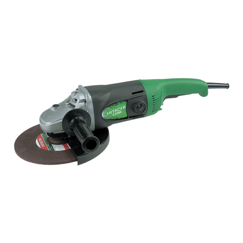
SIG PLB 291K Operating instructions

Page1
PLB 291 ROCKDRILL
SERVICE INSTRUCTIONS AND SPARE PARTS LIST
MODELS:
SIG.au PLB 291 DI

Page2
PLB 291 ROCKDRILL
Contents
PAGE
Safety Precautions 3
Technical Data, ratings 4
Operation 5
•Control elements
•Compressed air & flushing water
•Lubrication
•Drill Rods
Disassembling –Reassembling the Hammer 8
Parts & Maintenance Data 9
•Handle
•Backhead
•Control Lever
•Distribution system
•Piston
•Cylinder washer bush
•Rotating mechanism
•Chuck insert
Spare Parts List: SIG.au PLB-291DI 18
Exploded Drawing: SIG.au PLB-291DI 20

Page3
PLB 291 ROCKDRILL
SAFETY PRECAUTIONS
•During Operation of the drill, safety shoes, safety glasses, ear protection and safety helmet are to be
worn,
•Exposure to excessive noise can lead to hearing deficiency. APPROPRIATE ear protection must always
be worn.
•Distraction increases danger of accident.
•Only on actual operation of drill should the operating handle be touched.
•When working with the drill, sure and firm footing is necessary.
•The drill should not be brought near to the face.
•Never place the drill on your foot.
•Never point the drill at co-workers or yourself.
•The drill should never be put into operation if it is lying on the ground or if it is not held securely in
working position.
•Compressed air is dangerous! Never point a connected compressed air hose at co-workers or yourself.
Avoid the habit of blowing your clothes free of dust with compressed air.
•Be sure that all hose connections are tight and sealed. A loose hose not only causes loss of air; danger
exists that it comes completely off the drill, whips around injuring the operators and others in the
area. Secure hoses with safety cables or ropes to prevent danger of injury in case a hose gets broken.
•Never disconnect a pressurized air hose: First shut off air from the compressor and bleed the drill.
•The drill should only be operated with a specially suitable inserted drill rod. Operate with sufficient
pressure, avoid recoils. When the machine is under pressure, oilers may not be filled up and tools may
not be exchanged.
•The drill should always be held with both hands during operation.
•The operator must have a firm footing. If possible the operator’s feet should be so placed out of the
falling range of the drill, but without the danger of losing balance. In the case of breakage of drill rod,
there is danger of sudden falling of drill with protruding and broken drill rod part.
•Never operate drill astride, I.E., with one leg over the handle. In the case of breakage of the inserted
drill rod, serious injuries can result.
•Ensure that no cables, pipes and the like are in area of drill operation (electric, gas, water, telephone).
•In the event of drill contacting unknown objects during operation, switch off drill immediately.
Identification of object should be carried out by careful uncovering with shovel, not with the drill.
•In case a cleaning solvent is used for cleaning drill parts, make sure that this meets the current safety
and health regulations and that it is used in a well-ventilated area.
The safety precautions listed in the manual are intended to alert operator and helpers to the possible
physical dangers inherent in the various stages of operating and/or maintaining equipment of this kind. All
personnel involved in operating and/or maintaining this equipment must read and thoroughly understand
the operating instructions before attempting to operate, or perform maintenance on the drill machine. Non-
authorised, or untrained personnel must not under any circumstances attempt to operate or maintain the
machine.

Page4
PLB 291 ROCKDRILL
TECHNICAL DATA/RATINGS
Carefully memorize this tool’s operation and maintenance instructions.
PLB-29DI
PLB-29K
DIMENSIONS
Weight
30Kg
30Kg
Length
690mm
690mm
Piston diam.
90mm
90mm
Piston stroke
65mm
65mm
DRIVE
Impact rate
2700BPM
2700BPM
Optimal air pressure
5-6Bar
5-6Bar
Air Consumption
5.3m3/min at 6Bar
5.3m3/min at 6Bar
FLUSHING WATER
Water pressure: Always at least 0.5 bar LESS than actual air pressure
Water flow: 9 Litres/min with 2.4 long drill rod
Characteristics
Rotation: Left (Counter clockwise)
Exhaust Silencer: Integrated into hammer housing
Tool Insert: 22 x 108mm (7/8’’ x 4 1/4’’)
25 x 108mm (1’’ x 4 ¼’’ ) – alternative
Hoses
Air Hose: 25mm (1’’)
Water Hose: 13mm (1/2’’)

Page5
PLB 291 ROCKDRILL
OPERATION
1. Control Elements
A. Turning Handle for leg extension (SIG.au PLB-29K only)
B. Push button for leg retraction (SIG.au PLB-29K only)
C. Air pressure is shut off
D. Water flushing is ON
Reduced air pressure is ON (spot drilling)
E. Full air pressure is ON
F. Blow out of drill hole is ON
2. Compressed air and flushing water
Compressed air is to be CLEAN and DRY
Inner DIAMETER OF AIR HOSES to be 25mm or 1’’
Air hoses are to be BLOWN OUT BEFORE CONNECTION to the drill hammer
Inner DIAMETER OF WATER HOSES to be 13mm or ½’’
Water hoses are to be FLUSHED OUT BEFORE CONNECTION to the drill
Water pressure ALWAYS TO BE AT LEAST 0.5 Bar LESS than air pressure
SIG.au PLB 291K
SIG.au PLB 291DI

Page6
PLB 291 ROCKDRILL
3. Lubrication
When drilling, ALWAYS have the automatic oil feeder PLO 20 or a POB 15 fitted to the air
pressure line. (The closer the device is to the hammer, the safer it works).
Make Sure that oil shows up at the drill rod shank. The bit flange must be damp with oil. The
needed output may be regulated with the adjusting screw at the oil feeder.
ATTENTION: The oil feeder PLO 20 cuts off the air pressure when its reservoir runs out of
oil and/or when the air duct between oil feeder and hammer breaks.
The following oils for drill hammers are recommended:
AMBIENT TEMPERATURES
BRAND
TYPE
UNDER 100C
100C –350C
ABOVE 350C
TEXACO
RDL
32
100
SHELL
TORCULA
32
100
150
MOBIL
ALMO
525
527
529
4. Drill Rods
Rods
Shank ends are to be in good order, clean and
not worn or damaged. Percussion faces are to be
flat and perpendicular to the rod axis.
The flushing duct should not be clogged.
Bits
The correct section is to be ground (No cross cones!)
The flushing duct is not to be clogged.
For further details, please refer to the manufacturer’s instructions
Grinding –CAUTION!
If the cutting edge is ground
to a sharp corner like that on
the right, it may end up like the
broken edge on the left.
(See drawing to right)
The profile of the cutting head
should be wider than the mounting
steel to drill a hole with clearance.
(See drawing to right)

Page7
PLB 291 ROCKDRILL
Maintenance
The drill hammer is to be disassembled and cleaned periodically. At this opportunity the
particular wear parts are to be checked accordingly to chapter ‘Components and Servicing
Data’.
Dirt Restrictor
When replacing the dirt restrictor
Part 60, care should be taken to
insert it with Part 61 as shown.
All foreign matter must be removed
from the small holes and finally
blown out with compressed air.

Page8
PLB 291 ROCKDRILL
Disassembling the hammer
Screw off nuts, Part 13 with wrench B.
Push out frame bolts, Part 10.
So far, disassembly should be good enough for current servicing.
For directions concerning further disassembly, please refer to
‘Components and Servicing Data’.
Cleaning the parts
Carefully wash all parts with kerosene. Blow off residuals with compressed air and, with a
clean cloth, wipe the parts dry. After cleaning, coat all the parts with resin-free and acid-free
grease.
EXCEPTION: Do not grease but oil the valve plate, Part 74, the valve chest,
Part 72, and valve guide, Part 75.
Reassembling the Hammer
Replace all worn O-Rings as necessary,
Including control assemblies,
If found to be excessively leaking.
Reassemble the rock drill in accordance
With the exploded view. Make sure that the
distribution system, Parts 71, 72, 74, 75 & 76
are pressed vertically into the housing, Part 80.
Take care that the lubrication channel holes
In the cylinder washer, Part 84, and the
Housing, Part 80, line up.
Caution:
The frame-bolt nuts, Part 10,
Are to be screwed down alternatively
And in an uniform manner.
In the SIG.au PLB-29K and SIG.au PLB-291K
models, care is to be taken so not to jam
the valve piston, Part 128 inside the handle.

Page9
PLB 291 ROCKDRILL
Parts and Maintenance data
1. Handle (SIG.au PLB-29K and SIG.au PLB –291K models only)
Disassembly
Disassembly the left shaft bolt, Part 10.
Remove the head screw, Part 121.
Withdraw the left lever, Part 123.
Remove the supporting ring, Part 124.
Pull off the twist grip, Part 125, and check the
KSD –sealing rings, Part 126, and O-Rings, Part 127.
Assembly Instructions for KSD-rings
•Assembly tool, “spread bush”, is a self-made item, preferably made of nylon, delrin ore the
like.
•Twist grip 126 may be used as a calibrating tool.
•Lubricate KSD-rings with molycote, position O-ring once after the other in grooves via taper
guide.
•Add KSD-rings one after the other with aid of spread bush (handle gently)
•To recalibrate KSD-rings, use twist grip 125 in proper manner as shown.
Reassembly in reversed sequence:
Coat the KSD-rings 6 with MOLYCOTE
CAUTION: When mounting the twist grip 125 take care that the cylindric pin fits into the counter sunk
groove (b).

Page10
PLB 291 ROCKDRILL
Valve piston –inside handle (Model SIG.au PLB-29K and SIG.au PLB-291K only)
The valve piston, Part 130, may jam because of dirt or incorrect tightening of the side rod,
Part 10. Check it for easy movement.
To remove dirt that is causing jamming unscrew nut, Part 130, and remove the valve pin.
Clean and lubricate with a light, non-reinous oil before assembly. Tighten side rods, Part 10,
evenly to avoid binding.
2. Back Head (Handle Part)
The rubber seals must be in order to avoid water penetration inside the hammer. Defective
seals must be replaced by new ones, Parts 53 and 55.
Disassembly
Turn operating lever to position F and then pull off operating lever, Part 42, from valve, Part
33.
Eject throttle valve, Part 33, on air connection side.
If water emerges at the operating lever, Part 42, then O-ring 65 on valve pin, Part 66, must be
replaced.

Page11
PLB 291 ROCKDRILL
3. Control Lever
Disconnect the control lever from
The throttle valve by tapping the
Control lever, while it is in the
OFF position (C)
When reassembling the control lever
Into the housing,
Be careful not to jam it.
4. Distribution Systems: Standard & High performance
There is a standard and high performance
valve chest assembly. They are recognized
by a different diameter of the VALVE PLATE.
The high performance unit fitted to the SIG.au PLB-291K
and the SIG.au PLB-291DI models has a small outside
and a larger internal diameter valve plate.
NOTE: No separate parts
of the valve plate, valve guide
or valve chest, Parts 72,74 & 75
are interchangeable.
SIG.au PLB-29K & SIG.au PLB-29DI:
84mm Outside diameter
18mm Inside diameter
SIG.au PLB-291K & SIG.au PLB-291DI
70mm Outside diameter
20mm Inside diameter

Page12
PLB 291 ROCKDRILL
Disassembly –Distribution System
Loosen the 2 side nuts, Part 13
and separate the housing, Part 80
from the backhead, Part 70.
Press out the control section,
Parts 71, 72, 73, 74, 75 & 76,
And dismantle with the help of
Punch E as per drawing.
Check valve plate, Part 74, for indentations.
Max depth not to exceed 0.3mm.
5. Piston
Check guide and spiral flute for wear.
Maximum flute width 12mm if worn,
Substitute the piston.
Check the piston large diameter for
Wear.
Replacement is recommended when piston
Diameter is less than 89.85mm.
Check the percussion face for wear.
maximum depth of upset pocket 1.5mm.
The piston may be refaced by grinding.
CAUTION If replacing the piston,
Grind the UPLIFTED EDGE ONLY
DO NOT GRIND THE POCKETED SURFACE
6. Cylinder Washer Bush (Sealing Bush) Part 83
SIG.au PLB-29DI & SIG.au PLB-291DI Models only –
Replace Mounting Bracket Bush,
Item 04, when excessively worn.
NOTE:
Toavoid Bush slippage in the bore, do not
Apply oil or grease when replacing.

Page13
PLB 291 ROCKDRILL
Check inner diameter for wear.
Maximum inner diameter 38.2mm
If worn, push out sealing bush
using a 41.5mm diameter header,
(made on site), and a vice.
With the help of an old percussion
piston press in a new sealing bush.
CAUTION
The inner diameter of the sealing
bush must fit over the outer diameter
of the piston collar.
7. Rotating Mechanisms
Detent pawls, Part 96
Check the edges of the detent
pawls for wear.
Maximum radius of wear 1.5mm
If one edge is worn, reverse the
pawls. If both edges are worn, replace.
Detent pawl springs, Part 95
Check the detent pawl springs at
regular intervals.
Fatigued or defective springs
cause unsuitable rod rotation.
Substitute defective springs.
Pawl plunger, Part 94
Maximum acceptable wear of
Plunger keys 1.5mm.
If possible, replace the pawl plunger.
Ratchet Ring, Part 90

Page14
PLB 291 ROCKDRILL
Maximum wear on edge: Minimum twistspline width: 1mm
Radius 1.5mm after this limit, replace ratchet ring.
After this limit, replace
ratchet ring.
Chuck Nut, Part 91
Wear on splines:
min. spline width 1mm
If less than 1mm,
Replace guide bush.
CAUTION!
Left-Handed thread

Page15
PLB 291 ROCKDRILL
8. Chuck insert (drill socket), Part 93
At regular periods, check the
inner hexagon for face wear.
To do so, use the wear gauge.
Broken pistons and/or drill rods may be
The consequence of worn out drill sockets.
To Test:
1. Find the point of greatest wear ‘X’
2. Using a hexagonal gauge insert it at
This point
3. If the gauge goes in, right to the stop,
Change the chuck insert.

Page16
PLB 291 ROCKDRILL
9. Cylinder Liner Replacement
In order to maintain good air compression, it is important to check the cylinder liner bore
for wear, cracks, corroded and pitted surface. If replacement is required proceed as follows:
•Use safety glasses and leather gloves to avoid injury. Place the housing vertically on
the top of the open bench vice or lock the housing hard on the side of the vice on the
pivoting eye section.
•As the grub screw, which locates cylinder liner, is secured with “Loctite”, it is not
required to extract it from the housing when the cylinder liner requires replacement.
•Ensure that cylinder liner can be gently knocked out from the housing.
•Rapidly apply heat externally all over the alloy section for several minutes by moving
the oxygen torch tip approximately 50mm away from the housing. Heat all over
quickly so as to create thermal expansion on the housing. DO NOT APPLY ANY HEAT
TO THE CYLINDER LINER BOAR!
CAUTION!
Apply only 100 –125 degree heat to the housing. Do not apply excessive heat as this will
cause the alloy to lose its heat treated properties. This can be checked either by quick hand
touch or by applying a drop of water on the alloy housing. Knock out the cylinder liner with
a hammer and drift.
Inspect the surface and quickly clean if required. Re-lock the housing eye now in a vertical
position. Align the locating groove on the cylinder liner with the grub screw end which
protrudes in the bore, quickly slide the housing in the position and push the liner fully to the
spigot end.
*NOTE* This procedure should be completed quickly in order to ensure that the heat from
the housing will not transfer to the liner and cause it to jam before it is located fully in the
position. Allow to cool in air before assembling the drill. Ensure that there are no burrs or
sharp points inside the cylinder bore in order to avoid irreparable damage on the piston.

Page17
PLB 291 ROCKDRILL
Replacement of chuck insert
NOTE: Where possible, use a hydraulic press when changing the chuck insert.
CAUTION! If the chuck insert and chuck nut have to be changed at the same time, it is
preferable to change the chuck nut first, as the old chuck insert forms a better support
than the new one.
1. Position the chuck, Part 92,
in dismantling sleeve C.
2. Tap out the old chuck insert, part 93,
using dismantling drive D.
3. Tap new chuck insert gently and
Perpendicularly into position
NOTE: The radius at the collar
must point outwards
4. Use a press to force the chuck insert
Up to the stop using a cut off drill steel
as a driver.
NOTE: To avoid risk of chuck
insert slippage in the chuck bore,
do not apply oil or grease when
replacing.

Page18
PLB 291 ROCKDRILL
SIG.au PLB 29 Rockdrill Parts List
ITEM
QTY
DESCRIPTION
PART NUMBER
1
1
Mounting Bracket Bolt
64 000 111
2
1
Mounting Bracket Assembly (Inc 1 & 5)
For 3600rotation of airleg assembly
64 000 103
4
1
Bush
64 000 140
5
1
Nut
64 000 120
10
2
Side Rod Bolt
64 262 380
12
2
Spring Washer
64 255 460
13
2
Side Rod Nut
64 255 451
20
1
Water Hose
Inc. 21, 22, 23, 24, 25 & 26
64 258 401
21
1
Cylinder Liner
64 263 340
23
1
Gooseneck swivel –water
64 255 120
24
1
Connection Nipple –water
64 255 110
25
1
Rubber Ring
64 255 130
26
1
Strainer
64 259 730
30
1
Connection Nipple –air
64 258 060
31
1
Gooseneck Swivel –air
64 262 210
32
1
O’ring
64 996 170
33
1
Throttle Valve
64 262 030
34
1
O’ring
64 996 330
40
1
Hexagonal Nut
64 992 070
41
1
Spring Washer
64 994 270
42
1
Operating Lever
64 258 041
43
1
Laid in Spring Key
64 257 040
44
1
Latch or Index Pin
64 256 291
45
1
Pressure Spring for Latch Pin
64 256 300
50
1
Plug
64 258 080
51
1
O’ring
64 979 300
52
1
Copper Gasket Seal
64 258 090
53
1
Rubber Seal
64 255 170
54
1
Water Tube
64 248 082
55
1
Gasket Seal
64 262 410
56
1
Flush Water Tube Sleeve
64 262 401
60
1
Dirt Restrictor
64 263 231
61
4
Rubber Seal
64 262 200
62
1
Water Valve Screw Includes Part 63
64 262 060
63
1
O’ring
64 996 240
64
1
Water Valve Ball
64 259 080
65
1
O’ring
64 996 500
66
1
Water Valve Pin Includes Part 65
64 259 102
70
1
Backhead
64 262 020
71
1
O’ring
64 996 290

Page19
PLB 291 ROCKDRILL
72
1
Valve Chest
64 263 260
73
1
Cylindrical Pin
64 258 130
74
1
Valve Plate
64 244 320
75
1
Valve Guide
64 263 270
76
1
Damper Ring
64 914 091
80
1
Housing, Silenced
64 263 173
82
1
Piston
64 262 364
83
1
Cylinder Washer Bush
64 262 350
84
1
Cylinder Washer
64 262 120
90
1
Ratchet Ring Complete
64 262 332
9001
1
Rifle Nut/Ratchet Bush
64 262 333
9002
1
Ratchet Ring
64 262 340
91
1
Chuck Nut
64 262 320
92
1
Chuck
64 262 280
93
1
Chuck Insert 7/8’’ x 108mm
64 262 300
94
4
Pawl Plunger
64 258 352
95
4
Pawl Spring –Stainless
64 258 344
96
4
Pawl
64 257 111
97
1
Front Head
64 262 270
100
1
Steel Retainer 7/8’’ x 108mm
64 261 100
101
2
Heavy Type Dowel Pin
64 995 770
102
1
Steel Retaining Bolt
64 261 090
103
1
Rubber Mounting
64 262 220
110
1
D-Handle Complete
64 000 162
111
2
Nuts for Connection Stud
64 000 030
112
1
Connection Stud of D-Handle assembly
64 000 020
113
1
Left Hand Side of D-Handle assembly
64 000 210
114
1
Hand Grip of D-Handle assembly
64 000 240
115
1
Right Hand Side of D-Handle assembly
64 000 220
OPTIONS
93
1
Chuck Insert 1’’ x 108mm
64 262 310
100
1
Steel Retainer 1’’ x 108mm
64 261 130

Page20
PLB 291 ROCKDRILL
This manual suits for next models
3
Table of contents
Other SIG Tools manuals
